Table of Contents
Advertisement
Available languages
Available languages
Quick Links
No: 23272 – 05/21 rev. 2
Catalog Number • Numéro de Catalogue • Número de Catálogo: LMSW-105
Country of Origin: Made in China • Pays d'origine: Fabriqué en Chine • País de origen: Hecho en China
LMSW-105-U is BAA and TAA compliant (Product produced in the U.S.)
This unit is pre-set for Plug n' Go™ operation,
adjustment is optional.
For full operational details, adjustment and more features
of the product, see the DLM System Installation Guide
provided with Wattstopper room controllers, and also
available at www.legrand.us/wattstopper.
Installation shall be in accordance with all applicable
regulations, local and NEC codes. Wire connections shall
be rated suitable for the wire size (lead and building wiring)
employed.
For Class 2 DLM devices and device wiring: To be
connected to a Class 2 power source only. Do not reclassify
and install as Class 1, or Power and Lighting Wiring.
Do not apply cleaning solvent directly onto unit. Apply
cleaning solvent onto a cloth, then wipe the unit to clean it..
MOUNTING THE SWITCH
WARNING: Do not install to cover a junction box having Class 1, 3 or
Power and Lighting Circuits.
The illustrations show examples of free-topology wiring. The LMSW-105 communicates with all other Digital Lighting Management
devices connected to the low voltage DLM Local Network.
LMDM-101
LMSW-105
Occupancy Sensor
Dimming Switch
Scene Switch
LMDM-101
Dimming Switch
LMRJ Cables
CAUTION: TO CONNECT A COMPUTER TO THE DLM LOCAL NETWORK USE THE LMCI-100.
NEVER CONNECT THE DLM LOCAL NETWORK TO AN ETHERNET PORT –
IT MAY DAMAGE COMPUTERS AND OTHER CONNECTED EQUIPMENT.
Line Voltage
Class 2 0-10 Volt Control Wiring
LMRC-212
Line Voltage
Dimming
0-10 Volt
Ballast
Room
Controller
J-Box
0-10 Volt
Ballast
Wattstopper
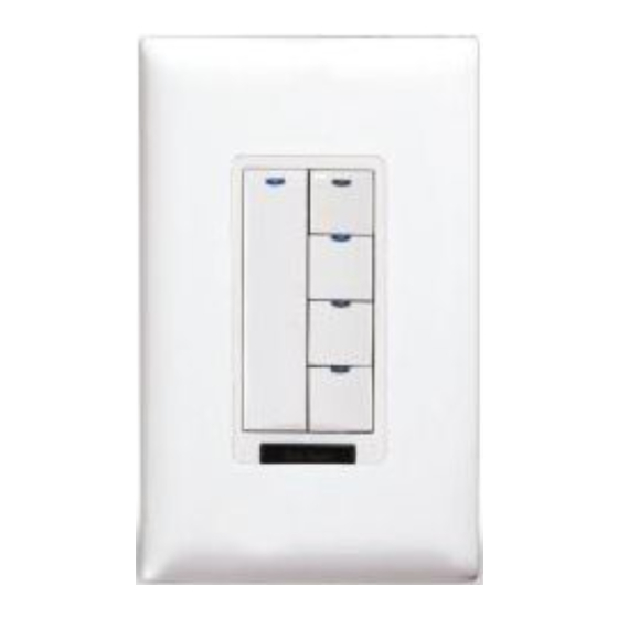
Digital Lighting Management Low Voltage Scene Switch (v3)
Interrupteur d'ambiance à basse tension (v3)
Interruptor de escena de bajo voltaje de control de iluminación digital (v3)
Quick Start Guide • Guide de démarrage rapide • Guía de inicio rápido
Voltage .............................................................................. 24VDC
Current Consumption .............................................................5mA
Power Supply ................Watt Stopper/Legrand Room Controllers
Connection to the DLM Local Network .................... 2 RJ-45 ports
DLM Local Network characteristics when using LMRC-11x/2xx
room controllers:
Low voltage power provided over Cat 5e cable (LMRJ);
max current 800mA. Supports up to 64 load addresses,
48 communicating devices including up to 4 LMRC-10x
series and/or LMPL-101 controllers.
Free topology up to 1,000' max.
Environment ................................................. For Indoor Use Only
Operating Temperature .................32° to 131°F (0° to 55°C)
Storage Temperature ...................23° to 176°F (-5° to 80°C)
Relative Humidity .......................5 to 95% (non condensing)
Patent Pending
Tap when load OFF:
Turn ON to last level
Tap when load ON:
Go to full bright
Press & Hold:
Ramp Up
Tap when load ON:
Turn OFF
Press & Hold:
Ramp Down
When all loads bound to the dimmer paddle are OFF, it's
Blue status LED is dim. When any load bound to the dimmer
paddle is ON it's Blue status LED is bright.
When a scene is active the LED on the scene button is bright.
CONNECTIVITY
Daylighting
Sensor
®
SPECIFICATIONS
BUTTONS AND INDICATORS
Corner Mount
Occupancy
Sensor
J Box
LMRC-21x
Room
Controller
To
Load
To 0-10V
Dimming Ballast
Blue Status LEDs
Scene Button (4)
Configuration Button
(behind switch plate)
Red LED
DLM Local Network
(low voltage, Class 2)
LMRJ cables
Ceiling Mount
Occupancy
Switch/
Sensor
Dimmer
Advertisement
Table of Contents

Related Manuals for LEGRAND Wattstopper LMSW-105


Summary of Contents for LEGRAND Wattstopper LMSW-105
- Page 1 For full operational details, adjustment and more features of the product, see the DLM System Installation Guide Power Supply ....Watt Stopper/Legrand Room Controllers provided with Wattstopper room controllers, and also Connection to the DLM Local Network ....2 RJ-45 ports available at www.legrand.us/wattstopper.
-
Page 2: Troubleshooting
Push n’ Learn. User Customization A user guide is available for the LMSW-105 from the wattstopper website: www.legrand.us/wattstopper. It describes basic operation and various procedures that can be used to make operational changes without tools or assistance from a technician. -
Page 3: Instructions En Français
Alimentation électrique ....Wattstopper contrôleur de pièce DLM fourni avec Wattstopper contrôleurs de pièce et aussi disponible au Connexion au réseau local DLM ........2 ports RJ-45 www.legrand.us/wattstopper. Caractéristiques du réseau local DLM pendant l'utilisation des contrôleurs LMRC-11x/2xx: L'installation doit être effectuée conformément à tous les règlements La basse tension est générée par le câble Cat 5e (LMRJ);... - Page 4 Personnalisation Un guide destiné aux utilisateurs du LMSW-105 est disponible sur le site Web du wattstopper à l'adresse: www.legrand.us/wattstopper. Il décrit le fonctionnement de base et les diverses procédures à utiliser pour apporter des modifications sans recourir à des outils ou à...
-
Page 5: Dépannage
Suministro de energía ..Controlador de habitación Wattstopper proporciona con Wattstopper controladores de habitación; también Conexión a la red local DLM ........2 puertos RJ-45 está disponible en www.legrand.us/wattstopper. Características de red local DLM al usar controladores de habitación LMRC-11x/2xx : La instalación debe realizarse conforme con todas las El voltaje bajo se suministra por un cable Cat 5e (LMRJ);... - Page 6 Personalización del usuario Se dispone de una guía de usuario para el LMSW-105 en el sitio web de wattstopper: www/legrand.com/wattstopper. Describe el funcionamiento básico y los distintos procedimientos que puede utilizar para realizar cambios operativos sin herramientas ni ayuda de un técnico.
-
Page 7: Solución De Problemas
2. Para desvincular un botón de una carga, presione el botón mientras que el LED azul está encendido. El LED azul se apaga para indicar que el botón ya no controla la carga que está actualmente activada. En el interruptor de escena, al desvincular una carga del botón de escena se elimina de la escena de manera que cuando se active la escena no cambie el estado de la carga. - Page 8 No. 23272 – 05/21 rev. 2 © Copyright 2021 Legrand All Rights Reserved. 800.879.8585 © Copyright 2021 Tous droits réservés Legrand. www.legrand.us/wattstopper © Copyright 2021 Legrand Todos los derechos reservados.
Need help?
Do you have a question about the Wattstopper LMSW-105 and is the answer not in the manual?
Questions and answers