Table of Contents
Advertisement
Advertisement
Table of Contents

Subscribe to Our Youtube Channel
Related Manuals for Orbit ERGO6.1 AIR ROWER


Summary of Contents for Orbit ERGO6.1 AIR ROWER
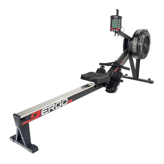
- Page 1 ERGO6.1 ERGO6.1 ERGO6.1 295 lbs/135 kgs.
-
Page 2: Table Of Contents
6. It is recommended that you place this exercise equipment on an equipment mat. 7. Set up and operate the ERGO6.1 AIR ROWER on a solid level surface. Do not position the ERGO6.1 AIR ROWER on loose rugs or uneven surfaces. -
Page 3: Before You Begin
It's a proven fact that a regular exercise program can improve your physical and mental health. Too often, our busy lifestyles limit our time and opportunity to exercise. The ERGO6.1 AIR ROWER provides a convenient and simple method to begin your journey of getting your body in shape and achieving a happier and healthier lifestyle. -
Page 4: Equipment Warning, Caution Labels
EQUIPMENT WARNING, CAUTION LABELS This chart is provided to help identify the warning, caution, and notice labels on the ERGO6.1 AIR ROWER. Please take a moment to familiarize yourself with all of the warning, caution, and notice labels. Label is larger than actual size CAUTION LABEL... -
Page 5: Hardware Identification Chart
HARDWARE IDENTIFICATION CHART This chart is provided to help identify the fasteners used in the assembly process. Place the washers or the ends of the bolts or screws on the circles to check for the correct diameter. Use the small scale to check the length of the bolts and screws. - Page 6 After unpacking the unit, open the hardware bag and make sure that you have all the following fasteners. Some fasteners may be already attached to the parts. Part Number and Description Pull Pin Foot Pedal End Cap Screwdriver Allen Wrench (6mm) Allen Wrench (5mm)
-
Page 7: Assembly Instructions
ASSEMBLY I NSTRU CTIO NS ASSEMBLY INSTRUCTIONS STEP 1 Attach FRONT SUPOORT LEG A(7) and FRONT SUPPORT LEG B(8) to FRONT STABILIZER(4) using: M6X16mm SOCKET HEAD CAP SCREW(81) and M6 FLAT WASHER(76). NOTE: Do not fully tighten bolts until instructed. #81 M6X1X16mm 4PCS #76 M6 4PCS Allen Wrench 5mm... - Page 8 ASSEMBLY I NSTRU CTIO NS STEP 3 Lift up the MAIN FRMAE(1) and RAIL FRAME(2), then insert RAIL FRAME(2) into the MAIN FRMAE(1). Fit the SHAFT(24) on the MAIN FRAME(1) into the gap of the RAIL FRAME(2). NOTE: Fully tighten bolts at end of this step. STEP 4 Insert the PULL PIN(98) into the MAIN FRAME(1) and RAIL FRAME(2).
- Page 9 ASSEMBLY I NSTRU CTIO NS STEP 5 Attach PEDAL SUPOORT PLATEs(5) to the MAIN FRAME(1) using: M10X160mm SOCKET HEAD CAP SCREW(84) and FOOT PEDAL END CAP(9). NOTE: Fully tighten bolts at end of this step. #84 M10X1.5X160mm 4PCS Allen Wrench 8mm...
- Page 10 STEP 6 Attach CELL PHONE BRACKET HOLDER(129) to the CONSOLE MONITOR (19), and tighten PHILIPS HEAD SCREW, ST4.2x10mm (75). Then attach CELL PHONE BRACKET (20) by using RUBBER BAND (21). STEP 7 Attach the CONSOLE MONITOR(19) to the CONSOLE MOUNTING BRACKET(69) using: M8X75mm BUTTON HEAD CAP SCREW(78), M8 FLAT WASHER(79), and M8 NYLON LOCK NUT(80).
-
Page 11: Computer Instructions
COMPUTER INSTRUCTIONS Your ERGO6.1 AIR ROWER utilizes an air fan system to create resistance for your workout. We recommend that you use this computer console to vary your workout from session to session and note your progress toward your fitness goals. When used regularly in this way, the computer console can become an important source of motivation and interest which will help keep you on track. - Page 12 COMPUTER INSTRUCTIONS II. FUNCTION BUTTONS PROGRAM BUTTON: In IDLE mode, press and release PROG to cycle through each program option. Stop on the program of your choosing. You can preset target values for DISTANCE, TIME, and CALORIES, or select an Interval Program of DISTANCE, TIME, and CALORIES.
- Page 13 COMPUTER INSTRUCTIONS III. CONSOLE DISPLAY S/M (STROKE RATE): Display the current stroke per minute during exercise. Display range: 1-99 STROKES: Display the total number of strokes during exercise. Display range 0-9999 TIME & D M Y Display range: 0:00:00 ~ 17:59:59 HOURS:MINUTES:SECOUNDS The workout time is accumulated when under any workout mode.
- Page 14 COMPUTER INSTRUCTIONS TIME /500M & AVE TIME/500M & TIME & REST TIME Display range: 00:00 ~ 99:59 (MINUTES : SECONDS) TIME/500M is the estimated time to reach 500M based on your current stroke rate AVE TIME/500M is the average time needed to reach 500M accumulated throughout your entire workout TIME is the TIME of the day, it is based on 00:00 ~ 24:00 format.
- Page 15 COMPUTER INSTRUCTIONS TIME (Countdown) PROGRAM During the workout, the “TIME” program will count down from preset value. Workout value setting range 00:00:20 ~ 09:59:59. The program will start once the user pulls the Handlebar. When the program is finished, the monitor will show your workout summary.
- Page 16 COMPUTER INSTRUCTIONS MEMORY MODE After pressing PROG button and you see MEMORY displayed, press ENTER to view your past workouts. Use the UP and DOWN buttons to scroll through your workouts. Press ENTER to view the workout data. Once in the data, you can press RIGHT and LEFT button to view your SPLIT data. Press STOP to go back and scroll to a different workout.
- Page 17 HOW TO INSTALL AND REPLACE BATTERIES: COMPUTER INSTRUCTIONS C Batteries 1. Open the Battery Door on the back of the CONSOLE MONITOR(19). 2. The CONSOLE MONITOR(19) operates with two C batteries (1.5V each), the batteries are not included. Refer to the illustration to install or replace the batteries.
-
Page 18: Operational Instructions
OPERATIONAL INSTRUCTIONS LOAD ADJUSTMENT DAMPER(42) RIGHT There built into SHROUD(43). Move the Indicator in the DAMPER(42) to point to the numbers on the RIGHT FAN SHROUD(43) to adjust the load. There are settings from 1 to 10. Setting #1 will provide the lowest resistance. - Page 19 7. Worn or damaged components must be replaced immediately or the ERGO6.1 AIR ROWER removed from service until repair is made. 8. Only Orbit supplied components should be used to maintain/repair the ERGO6.1 AIR ROWER 9. Keep your ERGO6.1 AIR ROWER clean by wiping it off with an absorbent cloth after use.
-
Page 20: Storage
3. Move the ERGO6.1 AIR ROWER with the TRANSPORT WHEELS(66) on the FRONT STABILIZER (4). Lift the Rear Stand of the RAIL FRAME(2) to move the ERGO6.1 AIR ROWER. Refer to the illustration below. Do not use the SEAT(51) to move the ERGO6.1 AIR ROWER. The SEAT(51) will move and the SEAT CARRIAGE(10) may pinch your hand or fingers. -
Page 21: Maintenance
MAINTENANCE BUNGEE CORD ADJUSTMENT Over time, about 250,000 strokes on HANDLEBAR(3), your BUNGEE CORD(38) may stretch. Follow the following process to adjust: 1. Position the MAIN FRAME ASSEMBLY(1) as shown in the illustration. Remove the MAIN FRAME CAP(68) from the MAIN FRAME(1). Slid out the BOTTOM COVER(70) from the MAIN FRAME(1). -
Page 22: Conditioning Guidelines
CONDITIONING GUIDELINES How you begin your exercise program depends on your physical condition. If you have been inactive for several years or are severely overweight, start slowly and increase your workout time gradually. Increase your workout intensity gradually by monitoring your heart rate while you exercise. Remember to follow these essentials: Have your doctor review your training and diet programs. -
Page 23: Warm-Up And Cool-Down
WARM-UP and COOL-DOWN Warm-Up The purpose of warming up is to prepare your body for exercise and to minimize injuries. Warm up for two to five minutes before strength training or aerobic exercising. Perform activities that raise your heart rate and warm the working muscles. Activities may include brisk walking, jogging, jumping jacks, jump rope, and running in place. -
Page 24: Product Parts Drawing
PRODUCT PARTS DRAWING... -
Page 25: Parts List
PARTS LIST PART# DESCRIPTION Main Frame Rail Frame Handlebar Front Stabilizer Pedal Support Plate Console Monitor Post Front Support Leg A Front Support Leg B Foot Pedal End Cap Seat Carriage Bungee Cord Hook Chain Bracket Stainless Steel Rail Perforated Steel Mesh Spacer, 8.2x 12x3.2mm Spacer, 8.2x 12x71.6mm... - Page 26 U Bolt Inner Spacer Outer Collar Bearing 6003RS Bearing 608ZZ Bearing 6201RS One Way Bearing HF2016 Chain Sprocket Bungee Cord Bungee Cord Pulley Chain Roller Bearing 6000ZZ Damper Right Fan Shroud Left Fan Shroud Foot Pedal Foot Pedal Holder Pedal Strap Spacer, 10x 16x30.5mm Pulley...
- Page 27 Bushing 6001 Bushing 6003 Guide Roller Seat Roller Roller Sleeve Transport Wheel Rail End Cap Main Frame Top Cap Console Mounting Bracket Bottom Cover Plastic Washer, 10.2x 14x1mm Phillips Head Screw, M6x10mm Lock Washer, Internal Tooth M6 Nylon Lock Nut, M6 Phillips Head Screw, ST4.2x10mm Flat Washer, M6 Socket Head Cap Screw, M8x65mm...
- Page 28 Nylon Lock Nut, M10 Phillips Head Screw, ST4.2x6mm Phillips Head Screw, M4x45mm Hex Nut, M4 Pull Pin Socket Head Cap Screw, M6x16mm Phillips Head Screw, M6x30mm (Full Thread) Phillips Head Screw, M6x10mm Screwdriver Allen Wrench, 6mm Wrench Hex Nut, M6 PU Spacer Plug Bearing, 6001RS...
- Page 29 Phillips Head Screw, ST4.2x10mm Nylon Lock Nut, M6 Allen Wrench, M8 Cell Phone Bracket Holder...
Need help?
Do you have a question about the ERGO6.1 AIR ROWER and is the answer not in the manual?
Questions and answers