Advertisement
Quick Links
Advertisement

Related Manuals for Orbit ORBITX305


Summary of Contents for Orbit ORBITX305
- Page 1 OrbitX305 OrbitX305 Assembly Instructions...
-
Page 2: Table Of Contents
25-26 Warranty Card..........................27-29 Owner’s Manual Orbit X305 CAUTION: Exercise of a strenuous nature, as is customarily done on this equipment, should not be undertaken without first consulting a physician. No specific health claims are made or implied as they relate to the equipment. -
Page 3: Table Of Contents
Spare parts list Description Note Qty. connection tube upright frame left upright frame right bending tube left bending tube right upper connection tube upper bending tube right upper bending tube left hexagon bolt M10x75 lock nut washer Φ10 washer Φ10 chin up bar upper plate pulley frame tube right... - Page 4 Spare parts list Description Note Qty. check ring pipe Φ button head socket screw M12x40 spring washer Φ12 washer Φ12 barbell rod inner pipe Φ rubber pad Φ60xΦ26x25 rubber pad Φ60xΦ26x42 guide rod hollow Φ25x1955 reinforcing plate weight stack hexagon bolt M10x20 wire Φ5x2745mm...
-
Page 5: Spare Part List
Spare parts list washer Φ8 core trainer powder metallurgy sleeve barbell rod cup big washer Φ25x10x2.0 hexagon bolt M10x95 dip bar left dip bar right barbell rod holder right barbell rod holder left barbell rod holder short left barbell rod holder short right long bar ship rod hand belt... - Page 6 Assembly step(1)explosion drawing No. Description Note Qty. connection tube upright frame left upright frame right bending tube left bending tube right upper connection tube upper bending tube right upper bending tube left hexagon bolt M10x75 lock nut washer Φ10...
- Page 7 Assembly step(1)drawing Assembly step(1)assembly instruction Fix bending tube left-4 fastening on upright frame left-2 using M10x75 hexagon bolt-9, Φ10 washer-11 and M10 lock nut-10 Fix bending tube right-5 fastening on upright frame right-3 using M10x75 hexagon bolt-9, Φ 10 washer-11 and M10 lock nut-10 Fix connection tube-1 fastening with bending tube left-4, bending tube right-5 using M10x75 hexagon bolt-9, Φ10 washer-11 and M10 lock nut-10 Fix upper connection tube-6 fastening on upright frame using M10x75 hexagon bolt-9, Φ10...
-
Page 8: Assembly(1
Assembly step(2)explosion drawing No. Description Note Qty. No. Description Note Qty. hexagon bolt M10x75 tube with hole right lock nut tube with hole left washer Φ10 lower plate chin up bar sliding tube right upper plate sliding tube left pulley frame tube right foot tube cover pulley frame tube left end tube... - Page 9 Assembly step(2)Enlarged View...
-
Page 10: Assembly(2
Assembly step(2)drawing Assembly step(2)assembly instruction 1 Fix sliding tube left-21 on tube with hole left-18 2 Fix sliding tube right on tube with hole right-17 Fix upright tube-16 and tube with hole left-18 fastening on assembly step-1 using M10x75 hexagon bolt-9, Φ10 washer-11, M10 lock nut-10, upper plate-13 and lower plate-19 Fix pulley frame tube right-14 and pulley frame tube left-15 fastening on upper plate-13 using M10x75 hexagon bolt-9, Φ10 washer-11 and M10 lock nut-10 Fix end tube-23 fastening on upper plate-13 using M10x75 hexagon bolt-9, Φ10 washer-11... -
Page 11: Upper Base
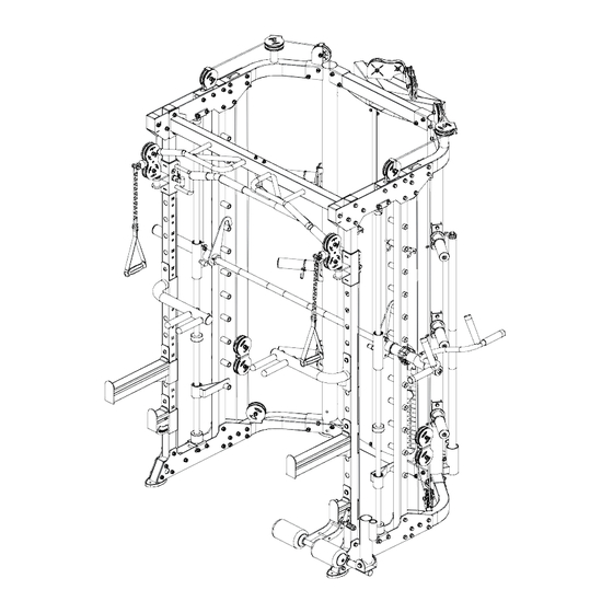
Assembly step(3)explosion drawing 35 40 39 38 No. Description Note Qty. No. Description Note Qty. lock nut socket set screw M8x10 washer Φ10 end cap lower base check ring upper base pipe Φ50x310xT0.5 guide rod Φ25x1850 button head socket screw M12x40 lock sleeve spring washer Φ12... - Page 12 Assembly step(3)drawing Assembly step(3)assembly instruction Fix lower base-25 fastening on lower plate using M10x90 hexagon bolt-33, Φ10 washer-11 and M10 lock nut-10 Fix upper base-26 fastening on upper plate using M10x90 hexagon bolt-33, Φ10 washer-11 and M10 lock nut-10 Guide rod in turn through lock sleeve-28, sliding sleeve-29, rubber pad-43, safety hook left- 32 and rubber pad with groove-30 fastening on base using M8x10 socket set screw-34 Barbell rod-41 in turn through sliding sleeve-29, check ring-36, inner pipe-42, pipe-37 and end cap-35 fastening using M12x40 button head socket screw-38, Φ12 spring washer-39...
-
Page 13: Assembly(3
Assembly step(4)explosion drawing No. Description Note Qty. washer Φ10 rubber pad Φ60xΦ26x42 guide rod hollow Φ25x1955 reinforcing plate weight stack hexagon bolt M10x20 selector rod weight pin... - Page 14 Assembly step(4)drawing Assembly step(4)assembly instruction 1 Fix weight pin-91 fastening on selector rod-90 Guide rod hollow-45 in turn through rubber pad-44, weight stack-47 and fastening on reinforcing plate-46 using M10x20 hexagon bolt-48, Φ10 washer-11 and M10 lock nut-10...
-
Page 15: Assembly(4
Assembly step(5)explosion drawing Wire port sliding sleeve outside of No. Description Note Qty. lock nut washer Φ10 wire Φ5x2745mm pulley Φ95 pulley plate hexagon bolt M10x45 hexagon bolt M10x50 hexagon bolt M10x25 weight... - Page 16 Assembly step(5)drawing Assembly step(5)assembly instruction 1 Connect wire-49 with weight-55, put them into upring frame Fix pulley-50 fastening on upper bending tube using M10x50 hexagon bolt-53, pulley plate- 51, Φ10 washer-11 and M10 lock nut-10 Fix pulley-50 fastening on upper bending tube using M10x45 hexagon bolt-52, Φ10 washer- 11 and M10 lock nut-10 Fix wire-49 fastening on sliding sleeve outside using M10x25 hexagon bolt-54, Φ10 washer- 11 and M10 lock nut-10...
-
Page 17: Assembly(5
Assembly step(6)explosion drawing Wire needs to keep vertical No. Description Note Qty. lock nut washer Φ10 hexagon bolt M10x80 pulley Φ95 hexagon bolt M10x45 hexagon bolt M10x25 wire Φ5x4095mm ”-“ shape pulley frame pulley spacer sleeve Φ20x10.5xL20.5... - Page 18 Assembly step(6)drawing Internal wire schematic Assembly step(6)assembly instruction As the shown in the figure fix pulley-50 fastening on upper plate using M10x80 hexagon bolt-24, Φ10 washer-11 and M10 lock nut-10 and pulley spacer sleeve-58 Fix pulley-50 fastening on ”-“ shape pulley frame-57 using M10x45 hexagon bolt-52, Φ10 washer-11 and M10 lock nut-10 As the shown in the figure put the wire-56 using M10x45 hexagon bolt-52, Φ10 washer-11 and M10 lock nut-10 fastening on bending tube, careful to keep the wire vertical...
-
Page 19: Assembly(6
Assembly step(7)explosion drawing No. Description Note Qty. hexagon bolt M10x80 lock nut washer Φ10 pulley Φ95 hexagon bolt M10x45 hexagon bolt M10x25 pulley spacer sleeve Φ20x10.5xL20.5 pulley Φ50 wire... - Page 20 Assembly step(7)drawing Internal wire schematic Assembly step(7)assembly instruction Fix pulley-50 fastening on ”-“ shape pulley frame-57 using M10x45 hexagon bolt-52, Φ10 washer-11 and M10 lock nut-10 Fix pulley-50 fastening on lower plate using M10x80 hexagon bolt-24, Φ10 washer-11 and M10 lock nut-10 and pulley spacer sleeve-58 Fix pulley-50 fastening on lower bending tube using M10x45 hexagon bolt-52, Φ10 washer- 11 and M10 lock nut-10 4 As the shown in the figure put the wire-60 on the machine...
-
Page 21: Assembly(7
Assembly step(8)explosion drawing No. Description Note Qty. barbell plate holder connection strap shield left shield right hexagon bolt M6x16 washer Φ6 hook “+"slotted countersunk head bolt M4x12 lock nut hexagon bolt M8x20 washer Φ8... - Page 22 Assembly step(8)drawing Assembly step(8)assembly instruction 1 Connect shield left-63, connection strap-62 and shield right-64 Fix hook-67 fastening on shield using “+"slotted countersunk head bolt-68 and M4 lock nut- 3 Fix shield fastening on main frame using M6x16 hexagon bolt-65, Φ6 washer-66 4 Fix barbell plate holder-61 on main frame using M8x20 hexagon bolt-70, Φ8 washer-71...
-
Page 23: Assembly(8
Assembly step(9)explosion drawing 76 11 No. Description Note Qty. lock nut washer Φ10 hexagon bolt M10x25 core trainer powder metallurgy sleeve barbell rod cup big washer Φ25x10x2.0 hexagon bolt M10x95... - Page 24 Assembly step(9)drawing Assembly step(9)assembly instruction Fix core trainer-72 fastening on main frame using M10x25 hexagon bolt-54, Φ10 big washer-75 and powder metallurgy sleeve-73 Fix barbell rod cup-74 fastening on upright frame using M10x95 hexagon bolt-76, Φ10 washer-11 and M10 lock nut-10...
-
Page 25: Assembly(9
Assembly step(10)explosion drawing No. Description Note Qty. dip bar left dip bar right barbell rod holder right barbell rod holder left barbell rod holder short left barbell rod holder short right long bar ship rod hand belt pull lift device T shape pin Φ10x100 leg curl tube... - Page 26 Assembly step(10)drawing Assembly step(10)assembly instruction 1 Connect leg curl tube-83 and barbell rod holder short left-81 using T shape pin-88 2 Put the attached part on the machine...
- Page 27 Faults as result of installation by Orbit staff must be reported within 7 days, as do concerns, questions aroused during or after installation by customer. Failure to follow warning in the owners manual, or warning stickers placed on...
- Page 28 Repair or replace any damaged or worn parts as early as possible so to avoid injury. As part of Orbit’s normal installation and set-up process, all bolts must be tightened and checked after the first 1 to 2 hours of initial usage and then periodically. Loose bolts and nuts may come off, causing damage, which may void warranty and can cause potential danger to the user as well.
-
Page 29: Warranty Card
Important Important Important ! Important ! WARRANTY CARD MUST BE COMPLETED AND RETURNED TO ORBIT OR REGISTERED ONLINE WITHIN 15 DAYS OF PURCHASE. Failure to comply may void manufacturer’s warranty. Name Address Email Phone Age group below 25 25-35 35-45...
Need help?
Do you have a question about the ORBITX305 and is the answer not in the manual?
Questions and answers