Carrier SINGLE PACKAGED ELECTRIC COOLING UNITS 50GS Installation And Operating Instructions Manual
Single packaged electric cooling units
Hide thumbs
Also See for SINGLE PACKAGED ELECTRIC COOLING UNITS 50GS:
- Operating and maintaining manual (4 pages) ,
- Manual (4 pages) ,
- Operating and maintaining manual (4 pages)
Table of Contents
Advertisement
Visit www.carrier.com
Installation, Start-Up, and Operating Instructions
50GS Sizes 018-060, 50GX Sizes 024-060
NOTE: Read the entire instruction manual before starting the
installation.
This symbol → indicates a change since the last issue.
TABLE OF CONTENTS
SAFETY CONSIDERATIONS .....................................................1
Introduction ....................................................................................2
RECEIVING AND INSTALLATION ..........................................2
Check Equipment......................................................................2
IDENTIFY UNIT ................................................................2
INSPECT SHIPMENT ........................................................2
Provide Unit Support ................................................................2
ROOF CURB.......................................................................2
SLAB MOUNT ...................................................................2
GROUND MOUNT ............................................................2
Provide Clearances....................................................................2
Field Fabricate Ductwork .........................................................2
Rig and Place Unit....................................................................2
INSPECTION ......................................................................3
INSTALLATION ................................................................3
Connect Condensate Drain .......................................................7
Install Duct Connections ..........................................................7
CAL) DISCHARGE ............................................................8
Install Electrical Connection ....................................................9
HIGH-VOLTAGE CONNECTIONS................................10
CONTROL VOLTAGE CONNECTIONS.......................10
STANDARD CONNECTION ..........................................10
TRANSFORMER PROTECTION....................................13
PRE-START-UP ..........................................................................13
START-UP ...................................................................................14
CHECK FOR REFRIGERANT LEAKS..........................14
MENTS ..............................................................................14
CHECKING COOLING CONTROL OPERATION .......14
CHARGE ...........................................................................14
MENTS ..............................................................................18
For 208/230V.....................................................................18
FOR 460-V GE MOTORS................................................18
COOLING SEQUENCE OF OPERATION.....................18
MAINTENANCE.........................................................................18
AIR FILTER......................................................................22
EVAPORATOR BLOWER AND MOTOR.....................22
DENSATE DRAIN PAN ..................................................24
CONDENSER FAN ..........................................................24
ELECTRICAL CONTROLS AND WIRING ..................24
REFRIGERANT CIRCUIT...............................................24
EVAPORATOR AIRFLOW .............................................25
Manufacturer reserves the right to discontinue, or change at any time, specifications or designs without notice and without incurring obligations.
Book 1 6
PC 101
Catalog No. 535-00130
Tab 6 8
Single Packaged Electric Cooling Units
Printed in U.S.A.
METERING DEVICE - ACUTROL DEVICE .............25
LIQUID LINE STRAINER ..............................................25
Troubleshooting............................................................................25
Start-Up Checklist ........................................................................25
NOTE TO INSTALLER - Before the installation, READ THESE
INSTRUCTIONS CAREFULLY AND COMPLETELY. Also,
make sure the User's Manual and Replacement Guide are left with
the unit after installation.
SAFETY CONSIDERATIONS
Installation and servicing of air-conditioning equipment can be
hazardous due to system pressure and electrical components. Only
trained and qualified personnel should install, repair, or service
air-conditioning equipment.
Untrained personnel can perform basic maintenance functions of
cleaning coils and filters. All other operations should be performed
by trained service personnel. When working on air-conditioning
equipment, observe precautions in the literature, tags, and labels
attached to the unit, and other safety precautions that may apply.
Follow all safety codes. Wear safety glasses and work gloves. Use
quenching cloth for unbrazing operations. Have fire extinguisher
available for all brazing operations. Consult a qualified installer or
service agency for information or assistance. The qualified in-
staller or agency must use only factory-authorized kits or acces-
sories when modifying this product.
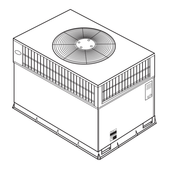
Fig. 1-Unit 50GS and 50GX
Form 50GS,GX-4SI
Pg 1
50GS, 50GX
C99001
9-03
Replaces: 50GS,GX-3SI
Advertisement
Table of Contents

Related Manuals for Carrier SINGLE PACKAGED ELECTRIC COOLING UNITS 50GS


Summary of Contents for Carrier SINGLE PACKAGED ELECTRIC COOLING UNITS 50GS
-
Page 1: Table Of Contents
Visit www.carrier.com Installation, Start-Up, and Operating Instructions 50GS Sizes 018-060, 50GX Sizes 024-060 NOTE: Read the entire instruction manual before starting the installation. This symbol → indicates a change since the last issue. TABLE OF CONTENTS SAFETY CONSIDERATIONS ...1 Introduction ...2 RECEIVING AND INSTALLATION ...2... -
Page 2: Introduction
Check all items against shipping list. Immediately notify the nearest Carrier Air Conditioning office if any item is missing. To prevent loss or damage, leave all parts in original packages until installation. -
Page 3: Inspection
REQUIRED CLEARANCE TO COMBUSTIBLE MATL. TOP OF UNIT...14.00 [355.6] DUCT SIDE OF UNIT...2.00 [50.8] SIDE OPPOSITE DUCTS ...14.00 [355.6] BOTTOM OF UNIT ...0.50 [12.7] ELECTRIC HEAT PANEL ...36.00 [914.4] NEC. REQUIRED CLEARANCES. BETWEEN UNITS, POWER ENTRY SIDE ...42.00 [1066.8] UNIT AND UNGROUNDED SURFACES, POWER ENTRY SIDE .36.00 [914.0] UNIT AND BLOCK OR CONCRETE WALLS AND OTHER GROUNDED SURFACES, POWER ENTRY SIDE...42.00 [1066.8] UNIT... -
Page 4: Unit Weight
REQUIRED CLEARANCE TO COMBUSTIBLE MATL. TOP OF UNIT...14.00 [355.6] DUCT SIDE OF UNIT...2.00 [50.8] SIDE OPPOSITE DUCTS ...14.00 [355.6] BOTTOM OF UNIT ...0.50 [12.7] ELECTRIC HEAT PANEL ...36.00 [914.4] NEC. REQUIRED CLEARANCES. BETWEEN UNITS, POWER ENTRY SIDE ...42.00 [1066.8] UNIT AND UNGROUNDED SURFACES, POWER ENTRY SIDE .36.00 [914.0] UNIT AND BLOCK OR CONCRETE WALLS AND OTHER GROUNDED SURFACES, POWER ENTRY SIDE...42.00 [1066.8] UNIT... - Page 5 HVAC unit base Scre w Gask eting (NO TE A) inner flange* *Gask eting outer flange Flashing field supplied Roofing mater i al field supplied Cant str ip field supplied *Provided with roofcurb Roof Curb for Small Cabinet Note A: When unit mounting scre w is used , retainer bra cke t must also be used.
- Page 6 CORNER # TOTAL WEIGHT Fig. 4B—50GS and 50GX Unit Corner Weights 2" 50GS MAXIMUM ALLOWABLE DIFFERENCE (in.) Fig. 5A—Unit Leveling Tolerances OPTIONAL RETURN OPENING EVAP. COIL COND. COIL Fig. 5B—Slab Mounting Detail 50GX OPTIONAL SUPPLY OPENING C99096 C00071 C99065...
-
Page 7: Maximum Weight
“B” SEE DETAIL A MAXIMUM WEIGHT SIZE Lifting point should be directly over the center of gravity for the unit. Step 6—Connect Condensate Drain NOTE: When installing condensate drain connection be sure to comply with local codes and restrictions. Models 50GS and 50GX dispose of condensate water through a 3/4 in. -
Page 8: Configuring Units For Downflow (Verti- Cal) Discharge
UNIT SIZE NOMINAL CAPACITY (ton) OPERATING WEIGHT (lb.) COMPRESSOR REFRIGERANT (R-22) Quantity (lb.) REFRIGERANT METERING DEVICE Orifice ID (in.) CONDENSER COIL Rows...Fins/in. Face Area (sq. ft.) CONDENSER FAN Nominal Cfm Diameter Motor Hp (Rpm) EVAPORATOR COIL Rows...Fins/in. Face Area (sq. ft.) EVAPORATOR BLOWER Nominal Airflow (Cfm) Size (in.) -
Page 9: Install Electrical Connection
1” (25mm) MIN. Table 3—Minimum Airflow for Safe Electric Heater 5. It is recommended that the unit base insulation around the perimeter of the vertical return-air opening be secured to the unit base with aluminum tape. Applicable local codes may require aluminum tape to prevent exposed fiberglass. -
Page 10: High-Voltage Connections
DUCT COVERS REMOVED Fig. 9—Vertical Duct Cover Removed Failure to follow these precautions could result in damage to the unit being installed: 1. Make all electrical connections in accordance with NEC ANSI/NFPA (latest edition) and local electrical codes governing such wiring. In Canada, all electrical connec- tions must be in accordance with CSA standard C22.1 Canadian Electrical Code Part 1 and applicable local codes. - Page 11 VOLTAGE UNIT 50GS RANGE V-PH-HZ SIZE 208/230–1–60 208/230–1–60 208/230–1–60 208/230–3–60 208/230–1–60 208/230–3–60 460–3–60 208/230–1–60 208/230–3–60 460–3–60 208/230–1–60 208/230–3–60 460–3–60 208/230–1–60 208/230–3–60 460–3–60 (See legend following Electrical Data charts) Table 4—Electrical Data—50GS COMPRESSOR ELECTRIC HEAT Nominal Kw* 3.8/5.0 5.4/7.2 7.5/10.0 3.8/5.0 12.8 5.4/7.2 7.5/10.0...
- Page 12 VOLTAGE RANGE UNIT 50GX V-PH-HZ SIZE 208/230–1–60 208/230–1–60 208/230–3–60 208/230–1–60 208/230–3–60 460–3–60 208/230–1–60 208/230–3–60 460–3–60 208/230–1–60 208/230–3–60 460–3–60 208/230–1–60 208/230–3–60 460–3–60 (See legend following Electrical Data charts) Table 5—Electrical Data—50GX COMPRESSOR ELECTRIC HEAT Nominal Kw 3.8/5.0 10.9 54.0 5.4/7.2 7.5/10.0 3.8/5.0 13.5 73.0...
-
Page 13: Transformer Protection
LEGEND — Full Load Amps — Locked Rotor Amps — Minimum Circuit Amps MOCP — Maximum Overcurrent Protection — Rated Load Amps CKT BKR — Circuit Breaker NOTES: 1. In compliance with NEC (National Electrical Code) requirements for multimotor and combination load equipment (refer to NEC Articles 430 and 440), the overcurrent protective device for the unit shall be Power Supply fuse . -
Page 14: Start-Up
leak. Leak test all refrigerant tubing connections using electronic leak detector, halide torch, or liquid-soap solu- tion. If a refrigerant leak is detected, see Check for Refrigerant Leaks section. c. Inspect all field- and factory-wiring connections. Be sure that connections are completed and tight. d. - Page 15 C99003 Fig. 12—Wiring Diagram (208/230-60-1)
- Page 16 C99004 Fig. 13—Wiring Diagram (208/230-60-3)
- Page 17 C99005 Fig. 14—Wiring Diagram (460-60-3)
-
Page 18: Indoor Airflow And Airflow Adjustments
When evaluating the refrigerant charge, an indicated adjust- ment to the specified factory charge must always be very minimal. If a substantial adjustment is indicated, an abnormal condition exists somewhere in the cooling system, such as insufficient airflow across either coil or both coils. Proceed as follows: 1. - Page 19 Table 8—Wet Coil Air Delivery (Deduct 10 percent for 208v)* Motor Unit Speed Watts 1000 Watts Watts High 1150 Watts Watts 1136 Watts High 1415 Watts Watts 1136 Watts High 1415 Watts Watts Watts High Watts Watts Watts High Watts Watts Watts High...
- Page 20 Table 9—Wet Coil Air Delivery (Deduct 10 percent for 208v)* Motor Unit Speed Watts Watts Watts High Watts Watts 1148 Watts High Watts Watts Watts High Watts Watts Watts High Watts Watts Watts High Watts 2190 Watts Watts High * Air delivery values are based on operating voltage of 230v or 460v, wet coil, without filter or electric heater. Deduct filter and electric heater pressure drops to obtain static pressure available for ducting.
- Page 21 Fig. 15—Cooling Charging Chart, 50GS018 Units Fig. 17—Cooling Charging Chart, 50GS030 Units Errors made when reconnecting wires may cause improper and dangerous operation. Label all wires prior to disconnec- tion when servicing. The minimum maintenance requirements for this equipment are as follows: 1.
-
Page 22: Air Filter
Fig. 19—Cooling Charging Chart, 50GS042 Units Fig. 21—Cooling Charging Chart, 50GS060 Units AIR FILTER Never operate the unit without a suitable air filter in the return-air duct system. Always replace the filter with the same dimensional size and type as originally installed. See Tables 1 and 2 for recommended filter sizes. - Page 23 (030) 60HZ CHARGING CHART Fig. 23—Cooling Charging Chart, 50GX030 Units (042) 60HZ CHARGING CHART Fig. 25—Cooling Charging Chart, 50GX042 Units c. On all units remove blower assembly from unit. Remove screws securing blower to blower partition and slide assembly out. Be careful not to tear insulation in blower compartment.
-
Page 24: Condenser Coil, Evaporator Coil, And Con- Densate Drain Pan
Fig. 27—Cooling Charging Chart, 50GX060 Units CONDENSER COIL, EVAPORATOR COIL, AND CONDEN- SATE DRAIN PAN Inspect the condenser coil, evaporator coil, and condensate drain pan at least once each year. The coils are easily cleaned when dry; therefore, inspect and clean the coils either before or after each cooling season. -
Page 25: Evaporator Airflow
System under pressure. Relieve pressure and recover all refrigerant before system repair or final unit disposal to avoid personal injury or death. Use all service ports and open all flow-control devices, including solenoid valves. If oil is detected or if low cooling performance is suspected, leak-test all refrigerant tubing using an electronic leak-detector, halide torch, or liquid-soap solution. - Page 26 SYMPTOM Compressor and condenser fan will not start. Compressor will not start but condenser fan runs. Three-phase scroll compressor (50GS048, 50GX030-060) makes excessive noise, and there may be a low pressure differential. Compressor cycles (other than normally satisfying thermostat). Compressor operates continuously. Excessive head pressure.
-
Page 27: Preliminary Information
(REMOVE AND STORE IN JOB FILE) I. PRELIMINARY INFORMATION Model No ... Serial No ... Date ... Technician ... Job/ Location... II. PRE-START-UP ____ Verify that all packing materials have been removed from unit ____ Verify that condensate connection is installed per installation instructions ____ Check all electrical connections and terminals for tightness ____ Check that indoor (evaporator) air filter is clean and in place ____ Verify that unit installation is level... - Page 28 Copyright 2003 CARRIER Corp. • 7310 W. Morris St. • Indianapolis, IN 46231 50gsgx4si Manufacturer reserves the right to discontinue, or change at any time, specifications or designs without notice and without incurring obligations. Book 1 6 PC 101 Catalog No. 535–00130 Printed in U.S.A.
Need help?
Do you have a question about the SINGLE PACKAGED ELECTRIC COOLING UNITS 50GS and is the answer not in the manual?
Questions and answers