
Related Manuals for WELLSYSTEM RELAX PLUS


Summary of Contents for WELLSYSTEM RELAX PLUS
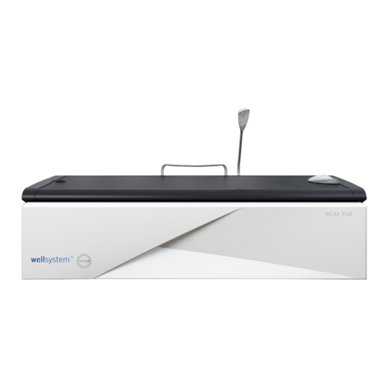
- Page 1 Dry water massage unit Operating instructions Translation of the original operating instructions wellsystem RELAX PLUS 1020143-00 / en / 0 .2022 wellsystem...
- Page 2 53578 Windhagen GERMANY Tel.: +49 (0) 22 24 / 818-257 Fax: +49 (0) 22 24 / 818-254 E-Mail: contact@wellsystem.com DANGER! Failure to observe these operating instructions: • can result in serious injury and death, • can result in damage to the unit and the environment.
-
Page 3: Table Of Contents
Table of contents Table of contents Safety instructions and warnings ..........5 General ....................5 1.1.1 Definitions .................... 5 1.1.2 Symbol explanation ................6 1.1.3 Symbols on the unit ................7 Intended use ..................8 Foreseeable misuse ................8 Safety information for the dry water massage system ...... 9 Safety instructions and warnings ............. - Page 4 Table of contents Service card ..................29 Default massage program ..............30 3.6.1 Selecting a massage program ............30 Loading a chip card ................31 Configuring the settings ..............32 3.8.1 Basic settings ..................32 3.8.2 Variable settings ................34 Cleaning and maintenance ............
-
Page 5: Safety Instructions And Warnings
Safety instructions and warnings Safety instructions and warnings To ensure safe operation of the unit, it is necessary to read the following safe- ty instructions and warnings carefully and comply with them. The safety instructions summarized here are repeated in the corresponding chapters, where necessary. -
Page 6: Symbol Explanation
Safety instructions and warnings 1.1.2 Symbol explanation The following types of safety notices are employed in these operating instruc- tions: DANGER! Type and source of hazard This safety notice indicates the existence of a direct danger to body and life. DANGER! Type and source of hazard This safety notice warns of dangers to body and life which... -
Page 7: Symbols On The Unit
Safety instructions and warnings 1.1.3 Symbols on the unit The following symbols are displayed on the unit or on the packaging: Manufacturer, production year and month Read and comply with the manufacturer’s documentation Electric unit label (do not dispose of via household refuse) ESD-sensitive components Stack a maximum of 2 units Maximum transport weight... -
Page 8: Intended Use
Safety instructions and warnings Intended use This unit is used to apply a dry water massage to one adult using the pro- grammes described in these operating instructions. More detailed information can also be found on pages 22 and 25. Infants and small children up to age 7 may not utilize this unit. -
Page 9: Safety Information For The Dry Water Massage System
Safety instructions and warnings Safety information for the dry water massage system The following people are not allowed to use the equipment: Persons with: Fresh wounds Acute inflammations Infections Suspected phlebitis and thrombosis (danger of embolism) Severely painful muscle stiffness with additional myogelosis (only target- ... -
Page 10: Safety Instructions And Warnings
Safety instructions and warnings Safety instructions and warnings 1.5.1 Operator's obligations As the operator you are responsible for providing clear operating, cleaning and maintenance instructions and ensuring the intended use and the proper operation of the unit by means of training and instruction for the personnel. Your operating instructions must enable the safe use and safe operation of the unit and take into account the characteristics and expertise of your com- pany and also the national work safety and environmental protection regula-... -
Page 11: Transport, Assembly And Setup
Safety instructions and warnings 1.5.4 Transport, assembly and setup The unit may not be installed on the pallet! 01/2022 1020143-00 Operating instructions – 11/52... - Page 12 Safety instructions and warnings The unit is delivered by a specialist company and assembled and set up by the manufacturer's own service personnel or by an authorized service com- pany. As the operator you are responsible for abiding by the electrical regulations applicable at the installation site as well as adhering to the stipulated water pressure and the permitted coolant temperature, see 'Setup location'.
- Page 13 Safety instructions and warnings Setup location WARNING! Overheating from inadequate cooling! The unit might be damaged! – Maintain the minimum distances from the walls! Dimen- sions are given on page 44. – Do not change, obstruct or block the air inflow and outflow to the unit or make any unauthorized changes to the unit.
-
Page 14: Commissioning
Safety instructions and warnings 1.5.5 Commissioning Initial commissioning will be undertaken by the manufacturer's own service personnel or by an authorized service company. The unit will be handed over ready for use. If the unit has not been used for a longer period of time then it must first be inspected by our customer service staff or by another authorized company before being put back into operation again. -
Page 15: Decommissioning
Safety instructions and warnings 1.5.7 Decommissioning The unit must be disconnected from the power supply in order to temporarily or permanently decommission it by pulling out the mains plug. You must abide by the legal disposal requirements when permanently de- commissioning the unit. -
Page 16: Directives
Safety instructions and warnings Packaging All packaging consists of 100 % recyclable materials. Packaging brought into circulation by the JK Corporate Group that is no longer required can be re- turned to the JK Corporate Group. Your partner agency or dealer will be hap- py to advise. -
Page 17: Signs And Stickers On The Unit
Safety instructions and warnings Signs and stickers on the unit Danger area warning signs and important information about components are attached to the unit. The signs shown below are examples. Ensure that the warning signs are always clearly recognisable and legible. Any missing warn- ing signs or stickers must be replaced. - Page 18 Safety instructions and warnings 2: ESD-sensitive component sticker (a) and 'Voltage present' warning sticker (b) (1009942-..) The sticker is located behind the front panel on the control box. 3: 'No export USA/Canada' sticker (84829-..) The sticker is located behind the front panel on the control box. 18/52...
- Page 19 Safety instructions and warnings Warning sticker (1009943-..) 01/2022 1020143-00 Operating instructions – 19/52...
-
Page 20: Warranty
Safety instructions and warnings Warranty Wellsystem guarantees to the customer for 24 months starting from handover that the goods do not present any faults which remove or decrease the value or the capability of the unit in normal use. The rubber blanket, toothed belt and drive motors are components of the unit that are subject to wear and tear in everyday use. -
Page 21: Description
Description Description Scope of delivery Dry water massage unit Technical documentation (instructions, brochures for error codes and default settings and additional documentation) Service card 12668-.. Headrest 801091-.. Pressure hose 50906-.. (10 m, 3/8"); Inlet: 1,5 MPa (15 bar) operating pressure Hose 50909-.. -
Page 22: Accessories (Optional)
Dry water massage involves the treatment of the body or individual parts of the body by kneading, pummelling, rubbing, stroking and pressing the mus- cles. In principle, mechanical massage with the wellsystem RELAX_PLUS can be used for all forms of symptomatic and asymptomatic tension in the entire back, gluteal and leg musculature. -
Page 23: Massage Areas And Massage Types
Description 2.4.1 Massage areas and massage types If you use a chip card, the program stored on it will run automatically. If you are not using a chip card then the full-body massage combined with the paral- lel stroke continuous massage will be activated after start-up. You can change the areas to be massaged and the type of massage at any time just by press- ing the relevant button. - Page 24 Description Massage types Button Function Button Function Parallel stroke massage Parallel massage For the parallel stroke For the parallel massage, massage, the massage both massage nozzles nozzles move back and move back and forth in forth along the length of the same direction to the the body.
-
Page 25: Operation
Operation Operation Application tips 3.1.1 Safety instructions WARNING! Damage to the nozzle carriage may occur. – Only lie down on the unit or leave it when it is at rest. Procedures before and during a massage: Clothing dyes or hair dye may lead to a discolouring of the rubber blan- ... -
Page 26: Operating Overview
Operation Operating overview Function Information 1 Display 4-digit 2 Massage time button — 3 Back length button 45, 55, 65 4 Neck / shoulder button Massage area 5 Plus button, minus button — 6 Lower body button Massage area 7 Whole body button Massage area 8 Zone button Massage area... -
Page 27: Starting A Massage
Operation Function Information 14 Program button Program selection 15 Point button Massage area 16 Upper body button Massage area 17 Lumbar area button Massage area 18 Speed button (nozzle carriage) Speed levels 19 Massage pressure button min. 0.5, max. 3.75 Starting a massage NOTE: If and how the massage time, massage areas and massage... -
Page 28: Using A Chip Card To Start
Operation 3.3.1 Using a chip card to start A set of chip cards loaded with 3 additional massage programs is available as an accessory – see page 30. NOTE: If and how the massage time can be selected depends on the presettings –... -
Page 29: Ending A Massage
Operation Ending a massage The massage will be terminated automatically after the set massage time has expired. A flashing StOP sign will be shown in the display. When the set massage time has expired, the nozzles move at high speed to the head end and then change to a smoothing, final massage. -
Page 30: Default Massage Program
Operation Default massage program There are 3 massage programs saved on the unit. Program 1: Whole body massage Program 2: Back massage Program 3: Shoulder massage A set of chip cards loaded with 3 additional massage programs is available as an accessory. -
Page 31: Loading A Chip Card
Operation Loading a chip card The chip cards can be topped up for further massage sessions as often as desired (see 'Presettings', page 46). When topping up, the chip cards are upgraded to a new software version and can no longer be used in units in which older software is used. Remaining credit Upgraded chip cards briefly display the number of massages left after they have been inserted. -
Page 32: Configuring The Settings
Operation Configuring the settings 3.8.1 Basic settings Increasing / decreasing the intensity of the display and the lights inside the buttons Operating button Basic settings / Display Remarks Display Standby mode: Press the plus or minus but- tons to alter the display’s Massage time button light intensity and the intensi- ty of the lights inside the... - Page 33 Operation Activating and interrupting the massage times Operating Basic settings / Remarks Display button Massage start: START / STOP button Press the START / STOP button. The unit switches on. Massage time display Massage time sequence: The display counts down in seconds, e.g.
-
Page 34: Variable Settings
Operation 3.8.2 Variable settings Massage time, massage pressure, speed and body size settings Operating Setting/ Remarks button display START / STOP button The unit switches on. Massage time display After starting: The variable settings can be defined separately for the specific massage areas and the massage types, e.g.: 1. - Page 35 Operation Operating Setting/ Remarks button display Altering the Press the speed button and hold for nozzle carriage speed, approx. 1 s. The display will flash. e. g. from Press the plus or minus buttons to set the value that you want. Factory setting: SP.15 Minimum and maximum speeds: 05 to 30 in increments of 1...
-
Page 36: Cleaning And Maintenance
Cleaning and maintenance Cleaning and maintenance Safety instructions for maintenance DANGER! Electricity throughout entire unit! Personnel danger due to electric shock or electric burns. – Before beginning work, pull out the mains plug or dis- connect all live lines. – Secure all of the disconnected connections against accidental reactivation. -
Page 37: Faults
Cleaning and maintenance Faults Error codes are output to the display to simplify troubleshooting: If an error occurs, the error code flashes on the display. If several errors occur, the error messages are displayed alternately. NOTE: Certain error messages can be switched off by pressing the START / STOP button. -
Page 38: Cleaning And Disinfection
Cleaning and maintenance Cleaning and disinfection DANGER! Infections can be spread by skin contact! All objects / unit parts touched by the user during use must be disinfected after every use: – Handle – Control panel – Rubber blanket – Frame –... -
Page 39: Cleaning The Surfaces
Cleaning and maintenance 4.3.2 Cleaning the surfaces WARNING! Do not rub with a dry cloth – danger of scratching! Failure to comply voids any warranty claims. – For the fast, hygienic and proper cleaning of surfaces, use specially developed cleaning agents. –... -
Page 40: Maintenance Performed By The Customer Service Department
Customer Service department NOTE: The maintenance work must be carried out in accordance with the service department's wellsystem RELAX_PLUS checklist. Inspection work that has been carried out correctly can be entered and confirmed in the service manual – see page 42. - Page 41 Cleaning and maintenance Maintenance performed by authorized, trained and qualified staff WARNING! Danger to people from maintenance work that has not been carried out! If maintenance work is not carried out, it can lead to material damage or personal injuries! –...
-
Page 42: Maintenance Performed By The Operator
Cleaning and maintenance Maintenance performed by the opera- 4.5.1 Daily visual inspection – Inspect the unit for leaks. WARNING! The unit might be damaged by moisture! – The unit may no longer be used in the event of water loss (puddles on the floor). Please inform our customer service department –... -
Page 43: Technical Data
Technical data Technical data Power, connection rating and weight wellsystem RELAX_PLUS Power consumption rating: 2600 W Rated frequency: 50 Hz Rated voltage: 230–240 V ~ Type of connection: Safety plug Rated fuses: External: 16 A Noise level 1m away from unit: 54.9 dB(A) -
Page 44: Dimensions
Technical data Dimensions A1 = 70 mm A2 = 70 mm BK = 2450 mm TK = 1900 mm L = 2150 mm B = 1060 mm H = 570 mm 44/52... -
Page 45: Presettings
Presettings Presettings Operating states can be called up and presettings entered in service / preset mode. See page 26. – Insert service card. – The code for the last function setting is displayed on the screen e.g. 06 and SER alternating. –... -
Page 46: Expanding The Chip Card Functions
Presettings Description On delivery Values from - to Pressure at massage start 1.50 0.50 - 2.75 Cooling time after massage 00–60 Cools when the preset setpoint temperature (07) is exceeded. Select: 0–60 minutes; ON runs continuously until the setpoint temperature is reached. Maximum pressure during the massage 3.75 0.50–3.75... - Page 47 Presettings 10: Number of massages / Chip card upgrade WARNING! Any credit remaining on the chip card will be overwrit- ten when topped up! – Check the remaining credit on the chip card. – Any new massages that are entered will be added to the remaining massages.
- Page 48 Presettings Button sequence Description Chip card (massage card) The LED in the time display will flash. Wait until the upgrade has been com- pleted (flashing stops). The card can be removed when 'Cout' is displayed on the screen. Service card Exiting sub-menu.
-
Page 49: Index
Index Index Accessories ......................22 Assembly ......................11 Care ........................38 Children ......................25 Chip card Loading ......................31 Cleaning ....................... 36, 38 Commissioning ....................14 Connection rating ....................43 Cooling conditions ..................... 43 Customer service ....................2 Decommissioning ....................15 Default massage program ................. - Page 50 Index Maintenance ....................... 36 Maintenance work Customer Service department ..............40 Operator ......................42 Massage areas ....................23 Massage start ..................... 27 Massage types ....................23 Operating altitude ....................13 Operating overview..................... 26 Operating water Disposal ......................15 Operator's obligations..................10 Packaging ......................
- Page 51 Index Technical data ....................43 Time control ....................... 14 Transport ......................11 Unit description ....................21 Unit operating time ..................... 14 Venting ....................... 42 Visual inspection ....................42 Warranty ......................20 Water conditions ....................43 Weight ........................ 43 01/2022 1020143-00 Operating instructions –...
- Page 52 Index 52/52...
Need help?
Do you have a question about the RELAX PLUS and is the answer not in the manual?
Questions and answers