Table of Contents
Advertisement
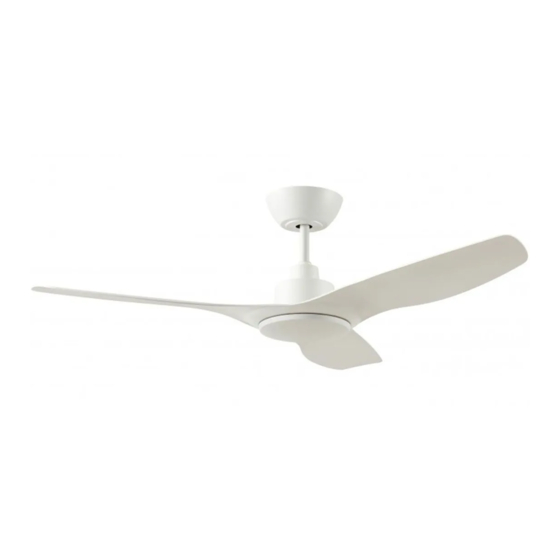
DC 3 Blade Ceiling Fan INSTRUCTION MANUAL
With LED (-L) model
Images are for reference only and may vary slightly from actual product.
Ceiling Fan Installation Manual
MODELS:
DC31203WH, DC31203WH-L, DC31203WHWC, DC31203WH-LWC
DC31203BL, DC31203BL-L, DC31203BLWC, DC31203BL-LWC
Thank you for purchasing this quality Ventair DC ceiling fan. To ensure correct function and safety,
please read all instructions before using the product and keep all instructions for future reference.
MUST BE
CAUTION
DIY
INSTALLED BY
Read Instructions Carefully
A LICENSED
For Safe Installation and Fan
ELECTRICIAN
Operation
Advertisement
Table of Contents

Subscribe to Our Youtube Channel
Related Manuals for Ventair DC 3 Series


Summary of Contents for Ventair DC 3 Series
- Page 1 DC31203WH, DC31203WH-L, DC31203WHWC, DC31203WH-LWC DC31203BL, DC31203BL-L, DC31203BLWC, DC31203BL-LWC Thank you for purchasing this quality Ventair DC ceiling fan. To ensure correct function and safety, please read all instructions before using the product and keep all instructions for future reference. MUST BE...
-
Page 2: Safety Precautions
SAFETY PRECAUTIONS WARNING: FOR SAFE USE OF THIS FAN, AN ALL-POLE DISCONNECTION MUST BE INCORPORATED INTO THE FIXED WIRING INACCORDANCE WITH THE WIRING RULES. As outlined in clause 7.12.2 of AS/NZS 60335-1 for meeting the minimum electrical safety of this standard. Please note warranty will be void if installation is without an all-pole disconnection incorporated in the fixed wiring in accordance with the wiring rules. -
Page 3: Before Installation
BEFORE INSTALLATION Unpack the fan carefully and identify all parts. Please refer to Fig 1. DC 3 WITH LIGHT DC 3 WITHOUT LIGHT Fig 1 Mounting bracket x 1 Mounting bracket x 1 Pre-assembled fan motor, down rod, canopy Pre-assembled fan motor, down rod, canopy and bottom cover x 1 and LED light x 1 Blades x 3... - Page 4 BEFORE INSTALLATION MOUNTING BRACKET • The ceiling fan must be installed in a location so that the blades have a minimum 300mm spacing from the tip of the blade to the nearest objects or walls. • Secure the hanging bracket to the ceiling joist or structure that is capable of carrying a load of at least 20kg, with the two Fixing screws provided.
-
Page 5: Hanging The Fan
HANGING THE FAN Lift the fan assembly onto the mounting bracket. Ensure that slot (A) of the hanger ball is fully aligned/engaged with the Tab (B) of the mounting bracket (C) to prevent the fan from rotating when in operation. Fig. 3) Secure the safety wire to the ceiling joist or other suit- able fixing point. - Page 6 FINISHING THE INSTALLATION • Connect fan to the receiver (can be done before or after sliding receiver into place). A. For fan models without light, plug cable marked ‘motor’ into remote control box. See Fig 7.2 B. For fan models with light, plug cable marked ‘motor’ and ‘LED’ into remote control box. See Fig 7.1 •...
- Page 8 )$9-%$'*-.%)-0' -($)"%,-.' <6' G4(+'Q#--'&Q13,2'3*'`LYa'8#+' 1&'+*Q'1+'&3#+/H.'"*/%6' X'`H%%5a'Q1--'H%'2%#(/6' !)'.*4(')#+'2#&'#'-1$23A'32%'-1$23' "#$!%&'()*!+,-.&/-!0,1.-! Q1--'1--4"1+#3%'1+'/%)#4-3'&%331+$' *)'<>>h'H(1$23+%&&'1+'NY?O' Y#34(#-' %45!FE<G!45B!FE%%G! Q213%'-1$236' %0:,4:B!N!B0,5B:4H.!H0:!100/&5'!C-8OO9:!O0B9D! %LM! M9@9:-9!N!86B:4H.!H0:!?94.!1&:18/4.&05!C,&5.9:!O0B9D! P51:94-9-!H45!-699B!85.&/!Q4R!C-699B!SD! ! " ! T91:94-9-!H45!-699B!85.&/!Q&5!C-699B!*D! +PQUM! M85!05!+&O9:!,&.?!#!-9..&5'!06.&05-!C*?:V!"?:-V!$?:-D! "#$!%&'()*!+,-.!0,1.-! & <0.9=!>&'?.!,&//!:941.&@4.9! 4.!6:9@&08-!A:&'?.59--!45B! 10/08:!C33+D!-9..&5'-!,?95! 8-&5'!?45B-9.!05/7)!E519!,4//! C&-0/4.&05D!-,&.1?!?4-!A995! .8:59B!FE%%G!>&'?.!,&//!B9H48/.! A412!.0!*IIJ!A:&'?.59--!!!!!!!!!!!!!!!!!!!!!!!!!!!!!!!!!!!!!!!!!!!!!!!!!!!!!!!!!!!!!!!!!!!!!!!!!! C<KD!<4.8:4/!,?&.9!/&'?.)! !!!!!!!!!!!!!!!!!!!!!!!!! %45!FE<G!45B!FE%%G! %0:,4:B!N!B0,5B:4H.!H0:!100/&5'!C-8OO9:!O0B9D! %LM! M9@9:-9!N!86B:4H.!H0:!?94.!1&:18/4.&05!C,&5.9:!O0B9D! P51:94-9-!H45!-699B!85.&/!Q4R!C-699B!SD! " T91:94-9-!H45!-699B!85.&/!Q&5!C-699B!*D! +PQUM! M85!05!+&O9:!,&.?!#!-9..&5'!06.&05-!C*?:V!"?:-V!$?:-D!
- Page 9 )$9-%$'*-.%)-0' -($)"%,-.' X"$"=,>&(,".&+(=&)".&+%*%(%"&4"(C&"F/=(%1" Handset '2%42@23! 21" V/+-%,("P(=/+%>*((,=Q".&+(=&)),=1" 31" Y,.,*E,=1"Y,.,*E,%">,%%/?,%"4=&>"(@,"@/+-%,("/+-"*%")&./(,-"*+"'FF,="./+&FA" &4"(@,"4/+1" X" R@,"NL":"=,>&(,".&+(=&)".&>,%"F=,<F/*=,-"/("(@,"4/.(&=A"/+-"*%"=,/-A"(&" '%,1" B/*=*+?"C*))"&+)A"D,"=,K'*=,-"*+"%*('/(*&+%">,+(*&+,-"D,)&C1" " P8(-9:;<(P(H>J@B>(DE;L9>B(B@(C@;BH@=(Q(@H(J@H>(34(R(6=EL>(4>:=:;<(GE;9( X" L@&&%,"(@,"4/+"A&'"C*%@"(&"F/*="C*(@"A&'="@/+-%,(1" " X" R'=+"*%&)/(*&+"%C*(.@"Z[#\"/+-"A:BD:;(QS(9>C@;L9(F=,%%"/+-"@&)-"" !!&+"(@," =,>&(,"4&=":"%,.&+-%1"R@,"4/+"C*))",>*("/"ZD,,F"D,,F\"%&'+-"(&"*+-*./(," (@,"F/*=*+?"F=&.,%%"*%"/.(*E/(,-1" X" B=,%%"" ! /+-".@/+?,"(@,"%F,,-"&4"(@,".,*)*+?"4/+"E*/"(@,"=,>&(,"(&".@,.M"(@," &F,=/(*&+"/+-"%'..,%%4')"F/*=*+?1" " Q8(0@99(@G(GI;CB:@;(@H(C@;BH@=(K>BA>>;(DE;L(?:>C>(E;L(H>C>:F>H( X" R=A"(@,"=,<F/*=*+?"F=&.,%%"/%"&'()*+,-"/D&E,"PF&*+("2Q1"J4"(@,"F=&D),>"F,=%*%(%!" ./))"],+(/*="(,.@+*./)"%'FF&=("&+"2:99"88;"^381" R8(#>?=EC:;<(E;(@=L(@H(LEJE<>L(DE;L9>B( X" J4"A&'"/=,"=,F)/.*+?"/"@/+-%,("&+)A"P+&("(@,"=,.,*E,=Q!"(@,"=,F/*=*+?"F=&.,%%" PF&*+("2Q"C*))"+,,-"(&"D,"F,=4&=>,-"D,4&=,"&F,=/(*&+"&4"(@,"4/+"*%"F&%%*D),1" " " "...
-
Page 10: Wall Control Operation
WALL CONTROL OPERATION Fan Models Without Light Power ‘ON’ and ‘OFF’ (isolation switch) Fan ‘ON’ and ‘OFF’. Forward-Downdraft for cooling (summer mode) Reverse-Updraft for heat circulation (winter mode) Increases fan speed until Max (speed 5) Decreases fan speed until Min (speed 1) Fan Models With Light Power ‘ON’... - Page 11 WALL CONTROL OPERATION ELECTRIAL WIRING DIAGRAM • Using 1 wall controller to control 1 DC 3 Blade Ceiling fan. 1. Connect “LIVE” supply to “L” of the wall controller. 2. Connect fan to “L1” of the wall controller. 3. Connect “NEUTRAL” to “N” of the wall controller. 4.
- Page 12 WALL CONTROL OPERATION ELECTRIAL WIRING DIAGRAM CONTINUED • Pair the Master fan. Pair the master fan first. Turn isolation switch “ON”, a ‘beep’ sound will be heard. Within 20 seconds, press and hold on the wall controller for 3 seconds. The fan will emit another ‘beep beep’ sound to indicate the pairing process has been successful.
-
Page 13: Important Facts
IMPORTANT FACTS Fan Operation: Fan Operation: DC 3 has been designed to optimise airflow with minimal amount of energy usage. Skyfan DC has been designed to optimize airflow with minimal amount of energy usage. A ceiling fan rotates much slowly than a traditional style wall, pedestal or desk fans; ceiling A ceiling fan rotates much more slowly than traditional style wall, pedestal or desk fans;... -
Page 14: Technical Information
• If you consider there is a manufacturer defect to the fan motor, contact the warranty service line on 1300 665 926, or submit a warranty claim at www.ventair. com.au/warranty You will need to provide the following information: • The name and contact details of the licensed electrician installer •...
Need help?
Do you have a question about the DC 3 Series and is the answer not in the manual?
Questions and answers
I have a Ventair DC3 Ceiling **** with CCT LED Light and Wall Control and need to remove the switch face plate to paint. how is it removed