
Related Manuals for Vivax Metrotech vLoc3-Cam


Summary of Contents for Vivax Metrotech vLoc3-Cam
- Page 1 User Handbook (English Edition) Version V1.0 P/N:4.04.000133 rrobertson@wctproducts.com | 13309 Beach Ave. Marina del Rey, CA 90292 Phone: 800-WCT-PROD (928-7763) | Fax: 310-306-9343 | www.wctproducts.com...
- Page 2 rrobertson@wctproducts.com | 13309 Beach Ave. Marina del Rey, CA 90292 Phone: 800-WCT-PROD (928-7763) | Fax: 310-306-9343 | www.wctproducts.com...
-
Page 3: Table Of Contents
3.4.8 Auto Power Off ..........................10 3.4.9 Bluetooth Pairing (Optional Feature) ..................10 3.4.10 Self-Test ............................10 Self-Test ..............................10 vLoc3-Cam Receiver Locate Screen Shots ................... 11 Using the vLoc3-Cam ............................13 Active Locating:- Applying the Transmitter .....................13 4.1.1 Direct Connection ........................13 4.1.2 Signal Clamp (83.1kHz) ......................14 4.1.3 Induction (83.1kHz) ........................16... - Page 4 4.4 Tracing a Buried Line ..........................18 4.5 Depth Measurement..........................18 4.6 Distorted Fields ............................19 4.7 Sonde Location Mode ..........................19 4.8 Active Location of the Camera Rod......................22 4.9 Passive Locating .............................24 4.9.1 Detecting Power Signals ......................24 4.9.2 Detecting Radio Signals......................25 4.10 Depth Measurement in passive modes ....................25 Connecting to External Devices ........................26 5.1 Bluetooth ..............................26 5.2 Pairing with external GPS/Dataloggers ....................26...
-
Page 5: General Safety & Care Information
General Safety & Care Information 1. General Safety & Care Information 1.1 Who Can Use This Equipment ● This equipment must only be used by people suitably trained in the use of pipe and cable locators. 1.2 Work-site Safety ● Use your company’s, or other applicable safety code and rules when using this equipment. ●... -
Page 6: Lithium-Ion Batteries (Rechargeable)
General Safety & Care Information ● If ever the product becomes hot during the charging process immediately unplug the charger and use the rechargeable batteries for at least ten minutes before recharging. If this reoccurs the next time the unit is charged – return immediately to Vivax-Metrotech for repair. -
Page 7: Care Of Equipment
General Safety & Care Information 1.5 Care of Equipment ● Use equipment only as directed in this User Handbook. ● Do not immerse any part of this equipment in water. ● Store in a dry place. ● Keep equipment in the case provided when not in use. ●... -
Page 8: Service & Support
Service & Support 2. Service & Support 2.1 Serial Number and Software Revision Number Always quote your receiver and transmitter model number, serial number and software revision number when requesting product support. They can be found as follows: (for reference only). Model &... -
Page 9: Distributors And Service Centers Closest To You
Service & Support 2.2 Distributors and Service Centers Closest to You: World Headquarters, United State of America Central/South America and the Caribbean Vivax-Metrotech Corporation Ventas para América Latina 3251 Olcott Street, 3251 Olcott Street, Santa Clara, CA 95054, USA Santa Clara, CA 95054, USA Website: www.vivax-metrotech.com T/Free : 800-624-6210... -
Page 10: Vloc3-Cam Receiver
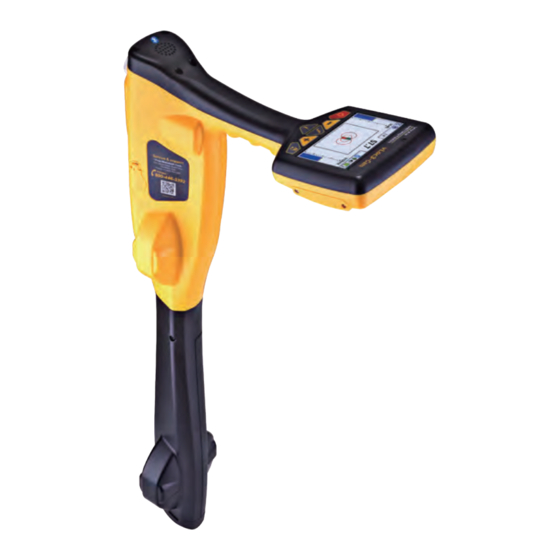
3.1 vLoc3-Cam Receiver Overview The vLoc3-Cam is a Precision Sonde Location System designed to meet the needs of plumbers, plumbing contractors, utility companies and their contractors or anyone looking to locate sondes. The following describes the features and use of the receiver. -
Page 11: Vloc3-Cam Receiver Keypad
Long press = enter User Set-up options 3.3 Battery Packs The vLoc3-Cam can be used with either alkaline batteries or an optional rechargeable battery pack. The central illuminated section within the battery icon indicates the amount of charge remaining. ● Blue center indicates Alkaline batteries ●... -
Page 12: User Menu
3.4 User Menu The vLoc3-Cam has several features that can be switched on and off. These features are accessed through the user menu. Switch on the unit by pressing and holding the On/Off key until the start-up screen appears. The start-up screen can be configured to the user’s preference and is described later in the manual. -
Page 13: About
Receiver Access to the User Menu is via the “i” button. Press and hold down the button until the menu appears. Menu Menu About Auto Power Off 10 Minutes Speaker Volume Bluetooth Pairing Sound Configuration Self Test Backlight Auto... -
Page 14: Language
Metrotech Corporation or one of its authorised service centers for repair. 3.5 Self-Test The vLoc3-Cam has a Self-Test feature. The test confirms that the equipment is fit for use and calibration has not drifted from its expected settings. To undertake the test, first find an area free from excessive interference such as overhead fluorescent lighting, large transformers etc. -
Page 15: Vloc3-Cam Receiver Locate Screen Shots
The user interface of the vLoc3-Cam is under continual development. The screen shots described may differ slightly from current screens. The vLoc3-Cam gives the user a choice of two different locate screens. The choice of screen depends on the application. ● Classic Line/Pushrod Locate Screen ●... - Page 16 Receiver The Classic Line/Pushrod Locate Screen has all the functions normally seen on a classic cable locator. The main functions being: 1.58m 78.9 26dB 83.1kHz Percentage signal strength (mirrors the bar graph setting) Peak level indicator Gain setting Bar graph signal strength indicator Compass line direction indicator (turns blue when aligned with target line) Frequency selection (flashing frequency indicates frequency selection is not valid for this screen.
-
Page 17: Using The Vloc3-Cam
Active location frequencies can be applied by direct connection, signal clamp or induction. (This is further explained in the following sections) the active frequency used in the vLoc3-Cam is 83.1kHz). Active locating has the benefit that, unlike passive detecting, the operator is in control of the signals and therefore can be more specific about what line is detected. -
Page 18: Signal Clamp (83.1Khz)
Using the vLoc3-Cam To make a direct connection, insert the direct connection connector to the transmitter. Insert the ground stake into the ground a few meters perpendicular to the line. Connect the black lead to the ground stake. Now take the red lead and connect to the target line. - Page 19 Using the vLoc3-Cam When clamping around a cable make sure the clamp is placed below the grounding point as shown below. When applying a clamp close to a grounding point where multiple grounds or a grounding bus exists, ensure that you place the clamp around the target line and not to the ground bus/other grounds This will help focus the applied signal to the target line.
-
Page 20: Induction (83.1Khz)
With no direct connection lead or signal clamp connected, the transmitter will automatically start to radiate a signal around the transmitter. These signals will penetrate the ground and couple onto buried lines. The signal will then travel along the line which can be detected with the vLoc3-Cam locator. Applying an induction signal to a line. -
Page 21: Locating Active Signals
It may be necessary to reduce the sensitivity to keep the bar graph on scale. This is normal and should be expected. Try to keep the vLoc3-Cam vertical and avoid swinging it as this may create false readings. -
Page 22: Tracing A Buried Line
If the depth measurement feature is activated, it is possible to take depth measurement estimations. To take a depth measurement, first pinpoint the position of the line/rod as above. Place the tip of the vLoc3-Cam on the ground making sure it is vertical and across the line ie the compass indicating Forward/Back. -
Page 23: Distorted Fields
Using the vLoc3-Cam Depth readings are only available in the sonde and 83.1kHz line mode. Depth is not available in the Power and Radio modes. The display shown above shows Longitude/Latitude positional information . To the top right is the hight above sea level. - Page 24 – a small peak with two “Nulls” between the peaks. The sonde is located under the center of the “large peak”. The vLoc3-Cam detects the presence of the two “Null” signals and also the position of the main “Large Peak”. It uses this information to provide a reliable and efficient method of sonde location.
- Page 25 Using the vLoc3-Cam Walk slowly in the direction of the arrow. A double circle will appear on the screen. This indicates the position of a null signal. Walk toward it and position it over the cross hairs of the screen. Now rotate the locator so that the arrow is pointing forward.
-
Page 26: Active Location Of The Camera Rod
Apply the transmitter as above. ο Switch on the vLoc3-Cam and use the f button to select the frequency that matches the transmitter. ο Note that the screen will now show the addition of a compass (line direction indicator). In the presence of a locate signal the compass will align itself parallel to the rod being located. - Page 27 As the end of the rod is reached the signal will rapidly reduce. This is to be expected. ο If the exact position of the camera is required, switch the sonde on at the control box and use the vloc3-Cam in the sonde mode to detect the camera head.
-
Page 28: Passive Locating
4.9.1 Detecting Power Signals 1. Switch on the vLoc3-Cam receiver and select Power mode using the “ f ” button. Notice that the antenna mode indicator will be showing “Peak” as this is the only antenna configuration available in the passive modes. -
Page 29: Detecting Radio Signals
31dB Power 60 7. Rotate the vLoc3-Cam on its axis to obtain the maximum signal. The vLoc3-Cam is now directly over the line and with the blade across the line. 8. The direction can also be found by rotating until the smallest signal is detected. The blade is then in line with the cable/pipe. -
Page 30: Connecting To External Devices
(see previous section on Bluetooth devices). Once paired with an external device, the vLoc3-Cam will await valid GPS data from the external device. The GPS icon will turn green when a valid GPS signal is detected. This can take from a few seconds to a few minutes depending on the device and whether it is doing a “cold”... -
Page 31: Mylocator3
A “MyLocator3” icon will appear on the computer desktop. MyLocator3 Connect your vLoc3-Cam to your computer via the mini USB connector which can be found under the battery cover flap. Launch MyLocator3 by double clicking on the icon. 6.2 My Locator3’s Basic Operation MyLocator3 operation, not requiring a USB security dongle. -
Page 32: Application Update
MyLocator3 6.2.2 Application Update Every time the MyLocator3 Application is started its version number is checked against the latest version available on the Vivax- Metrotech server and the user is notified if an update is available as shown below. This feature will only be available if the computer is “online”. -
Page 33: Locator Firmware Update
MyLocator3 6.2.3 Locator Firmware update Each time a locator is connected to the PC, it’s firmware version is checked against the latest version available on the Vivax- Metrotech server and the user is notified if an update is available as shown below. This feature will only be available if the computer is “online”. -
Page 34: Toolbar
6.3 Toolbar The vLoc3-Cam locator can be configured so that features can be switched on or off. This enables the user to tailor the instrument to meet the needs of their application while keeping the user interface uncluttered. The toolbar at the top of the screen enables the user to create configurations. -
Page 35: Frequencies Page
MyLocator3 6.6 Frequencies Page The “Frequencies” page will allow the user to refine which frequency modes are available when the locator F-key is pressed and which frequencies appear on the locator menu. rrobertson@wctproducts.com | 13309 Beach Ave. Marina del Rey, CA 90292 Phone: 800-WCT-PROD (928-7763) | Fax: 310-306-9343 | www.wctproducts.com Page 31 of 36... -
Page 36: Menu Settings
MyLocator3 6.7 Menu Settings The “Menu Settings” page allows the user control over which menu items appear on the locator and also the initial setting of the menu item when the locator is first used after configuration. The menu items with a right pointing arrow can be expanded to reveal further sub-menu items. -
Page 37: Accessories & Options
Attach the VM-550FF transmitter to the reel to trace the path of the deployed pushrod. Also use with the vLoc3-Cam receiver to trace the path of buried pipes or cables. The transmitter is supplied with direct connection leads and ground stake. -
Page 38: Clamps
Accessories & Options D38-09-AA Sonde ● 1.5in (38mm) x 4.1in (105mm) long, 9.8 kHz, range 16.3ft (5m). ● 1 x AA battery. D38-83-AA Sonde ● 1.5in (38mm) x 4.1in (105mm) long, 83 kHz, range 16.3ft (5m). ● 1 x AA battery. D64-33-LR61 Sonde ●... -
Page 39: Receiver Battery Charger
Accessories & Options 7.7 Receiver Battery Charger The receiver Lithium-ion battery charger is supplied as a standard item. It is powered from the mains supply (100-250V AC). 7.8 Ground Spool Used to extend the ground connection to a suitable grounding position. rrobertson@wctproducts.com | 13309 Beach Ave. -
Page 40: Glossary
Glossary 8. Glossary Active Locate A locate where a transmitter is used to apply a signal to a buried pipe or cable, the position of which is then located by a receiver tuned to the same frequency. Active Signal A signal applied by the locator transmitter to a buried line. Typical this is a very precise frequency. - Page 41 Notes: rrobertson@wctproducts.com | 13309 Beach Ave. Marina del Rey, CA 90292 Phone: 800-WCT-PROD (928-7763) | Fax: 310-306-9343 | www.wctproducts.com...
Need help?
Do you have a question about the vLoc3-Cam and is the answer not in the manual?
Questions and answers