
Related Manuals for Vivax Metrotech HL5000


Summary of Contents for Vivax Metrotech HL5000
- Page 1 M o d e l H L 5 0 0 0 El e c t r o a c o u s t i c L e a k L o c a t o r Operation Manual...
- Page 2 ISO 9001:2000 CERTIFIED Metrotech has received ISO 9001 Quality Management System Certification. Metrotech adheres to the quality standard guidelines of ISO 9001 and ensures quality in its design/development, production, installation, and servicing disciplines. © Metrotech Corporation 2006 Metrotech Corporation 3251 Olcott Street Santa Clara, CA 95054 Tel: 1.800.446.3392;...
-
Page 3: Table Of Contents
Filter Selection B: Contact Microphone (PAM U 40 with Spike or Rods) 3.6.3 Leak Detection Process and Filter Selection Mute Button The Memory Mode Continuous Measurement Mode (HL5000 Professional) 3.10 Pipe Locating Using the RSP-3 (HL 5000 Professional) 3.11 Switching off the HL5000... - Page 4 Troubleshooting Unit Does Not Switch On Battery Monitor Does Not Function No Sound Can Be Heard Scratching Sounds In the Headphones Service Center Appendix .. 24 Copyright Notice List of illustrations Fig 1 : HL 5000 Control Panel Fig 2 : Side view left and right with connections ..
-
Page 5: Description
Description General The new HL 5000 Leak Locator is designed to facilitate the implementation of a complete water leak detection program - from the preliminary survey, to pre-location, to pinpointing. Although designed with the water utility in mind, the HL 5000 can also be used for finding leaks in any pipe distribution network from which pressurized liquid creates sound when escaping from a leak. -
Page 6: Construction
Construction The construction of the HL 5000 is solid. The durable plastic housing of the receiver is water resistant and built to withstand normal field operation. The comfortably spaced soft keys on the front of the control panel allow even a gloved operator to easily navigate between features. -
Page 7: Hl 5000 Configurations
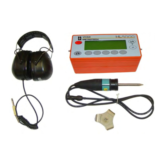
HL 5000 Configurations 1.4.1 HL 5000 -1 Includes receiver w/standard software, universal PAMU40 microphone, cable, 2-extension rods, contact spike, tri-point ground plate, hard case and operation manual. 1.4.2 HL 5000 -2 Includes receiver w/standard software, universal PAMU40, wind protected GM-50 microphones, cable, 2-extension rods, contact point, tri-point ground plate, hard case and operation manual. -
Page 8: Getting To Know The Hl 5000
Before using the HL 5000 , it is recommended that you take some time to become familiar with the unit and its features. 2.1 HL 5000 Controls Fig 1 : HL5000 Standard/Pro control panel 2.2 Connection of Components and Accessories... -
Page 9: Battery Compartment
Fig 2 : Side view left and right with connections Battery Compartment To access the battery compartment, loosen the two screws on the underside of the unit and remove the base plate (Fig.3). Eight AA batteries power the HL 5000 . When installing or replacing batteries in the unit, be sure that the positive and negative terminals of each battery are correctly aligned. -
Page 10: Automatic Battery Monitoring
2.4 Automatic Battery Monitoring While the HL 5000 is in operation, the battery level is monitored continuously. The battery symbol in the top right of the display will begin to flash when there are approximately 4 hours of battery life remaining. 2.5 Backlight With the equipment on, briefly push the on/off button The backlight for the display will be activated / deactivated. -
Page 11: Pam U
2.6.2 PAM U 40 Universal Microphone The PAM U 40 is a piezo-electric microphone that was developed primarily as a contact and/or survey microphone. With the use of various adapters, however, it is very effective in nearly all leak detection situations. Sensor Rod Configuration: This configuration allows the operator to quickly survey the distribution system for leak sound by... -
Page 12: Headphones
Caution: Whenever possible, grasp and pull the microphone itself not the cable when removing the microphone from a magnetic contact point. This will help prevent possible damage to the microphone cable Headphones The supplied headphones with ambient sound insulation come standard with the HL 5000 . These electro-dynamic headphones provide excellent reproduction of leak sounds while blocking out ambient sound to 85 dB. -
Page 13: Operation
Operation Connection and Removal of Attachments Always make sure that the HL 5000 is off when connecting or removing the headphones or the microphone. 3.2 Turning the Unit On After attaching both a microphone and the headphones, press the On/Off button on the control panel of the unit. -
Page 14: Headphone Volume And Microphone Amplification (Gain)
Fig 8 : Main Screen with Main Menu Headphone Volume and Microphone Amplification (Gain) The HL 5000 is equipped with separate controls for volume and gain to accommodate different user preferences across a variety of leak detection situations. 3.3.1 Setting the volume The user can set the headphone volume by using the two soft keys on the far right of the front panel (see Fig. -
Page 15: Setting The Gain
3.3.2 Setting the gain The amplification of the microphone signal, or gain, adjusts the level of sound passed from the microphone to the receiver for processing. A high gain setting would allow the equipment to detect and process far-off and/or low-level sounds more easily;... -
Page 16: The Main Screen
The Main Screen When performing leak detection, one of the difficulties faced by operators is how to identify and measure the sound made by a leak when other interfering sounds are also present. The HL 5000 utilizes a feature called Dual Segment Analysis (DSA) to differentiate between the two types of sounds. -
Page 17: Filter Settiing (Hl 5000 Professional)
Filter Setting (HL 5000 Professional) 3.5.1 What are filters? One of the characteristics of a sound is its frequency. Technically speaking, the frequency of a sound is the number of waves generated by that sound per cycle. The greater the number of waves per cycle, the higher the frequency of the sound. - Page 18 1. On the Filter Selection screen, a horizontal bar will be displayed beneath the selected filter or filters (Figure 12). When the unit is placed in normal Listening Mode (the Main Screen), Memory, or Continuous Listening Modes, the HL 5000 will focus on measuring the constant, minimum leak sound levels of only the frequencies selected by the user on the Filter Selection screen.
-
Page 19: Fig 12 : Filter Settings
Fig 12 : Filter settings Fig 13 : Adjusting the lower filter cut-off frequency Fig 14 : Adjusting the upper filter cut-off frequency... -
Page 20: Filter Selection In The Field
After the filters have been selected, use the ESC soft key to return to the main menu. Filter selection in the field Filter selection on the HL 5000 is largely determined by the type of pipe material the suspected leak is on and whether the operator is pre-locating or pinpointing the leak. -
Page 21: Mute Button
according to the above guidelines. It is possible, however, for leak sounds to be outside of the expected filter settings so a more systematic, 2-stage process is recommended: 1. Select all available filters and survey the system for any leak sound. When potential leak sound is detected, continue pre-location with all filters active until the loudest area of sound is located. -
Page 22: The Memory Mode
The Memory Mode The Memory Mode function is used to compare a series of sequentially recorded measurements and can be used for pre- locating or pinpointing leaks. To activate the memory mode function, press the memory soft on the control panel (Fig. 1). The LCD display simultaneously switches to the memory mode screen and the first memory measurement is activated. - Page 23 To exit the memory mode, press the ESC soft key. Continuous Measurement (HL5000 Professional) Continuous Measurement mode allows the operator to set the microphone in position and monitor sound levels at that location over short periods of time. Operators often use this feature to see what happens to a leak sound when a nearby valve is closed and re-opened.
- Page 24 Pressing the ESC soft key will exit the continuous measurement mode and return the user to the main screen. 3.10 Pipe Location Using the RSP-3 (HL5000 Professional) Most of today s technology for locating non-metallic water lines involves creating sound impulses on the water line itself and then tracing the line by hearing those sounds with an acoustic listening device like the HL 5000 .
-
Page 25: Switching Off The Hl5000
To enter Pipe Location Mode, press the impulse image soft key (second soft key from left) while the Welcome Screen is still displayed. When in Line Location Mode, the impulse image will be visible in the top left corner of the Main Screen and the measured sound level will be displayed by a single, wide bar. -
Page 26: Battery Monitor Does Not Function
Troubleshooting Unit Will Not Switch On Check to make sure batteries are correctly installed. Replace batteries. Battery Monitor Does Not Function Check to make sure all batteries are correctly installed. Replace batteries. No sound can be heard Check the headphone connection. Press the mute button to restore the sound. -
Page 27: Service Center
Service Centers If the instrument does not function properly, replace the batteries as described above. If the equipment still malfunctions, contact one of our Metrotech Customer Service departments for assistance: Vivax-Metrotech Corporation EuropeSebaKMT 3251 Olcott Street, Seba Dynatronic Santa Clara, CA 95054, USA Mess-und Ortungstechnik GmbH Website : www.vivax-metrotech.com Dr.-Herbert-Iann-Str. -
Page 28: Appendix
APPENDIX A1 APWA Marking Colors - The following color markings have been established by the American Public Works Association (APWA): Conductor Color ______________________________________________ Electric power lines, cables, or conduits ______________________________________________ Communication lines, cables, conduits, CATV Orange ______________________________________________ Gas, oil, petroleum, or other gaseous materials Yellow ______________________________________________... -
Page 29: Copyright Notice
COPYRIGHT NOTICE The information contained in this document is for informational purposes only and is subject to change without notice. Metrotech Corporation makes no warranty of any kind with regard to the information contained in this manual, including but not limited to the implied warranties of merchantability and fitness for a particular purpose. - Page 30 WARRANTY THERE ARE NO WARRANTIES, EXPRESSED OR IMPLIED, INCLUDING ANY WARRANTY OF MERCHANTABILITY, BEYOND THOSE STATED HEREIN. Metrotech warrants its equipment to be free from defects in workmanship and material under normal and proper use and service for one year from date of purchase by original user. Metrotech assumes no obligation to repair or replace equipment which has been altered or repaired by other than a Metrotech-approved procedure, been subject to misuse, misapplication, improper maintenance, negligence, or...
Need help?
Do you have a question about the HL5000 and is the answer not in the manual?
Questions and answers