
Related Manuals for Dometic Go Power! GP-RVC-R


Summary of Contents for Dometic Go Power! GP-RVC-R
- Page 1 RV-C REMOTE DISPLAY User Manual GP-RVC-R © 2021 Go Power! Worldwide Technical Support and Product Information gpelectric.com Go Power! | Dometic 201-710 Redbrick Street Victoria, BC, V8T 5J3 Tel: 1.866.247.6527 GP-RVC-R Manual...
- Page 2 Congratulations on purchasing your Go Power! RVC Remote. This remote is compatible with the GP-RVC-30-MPPT and GP-RVC-10-MPPT Solar Controllers Record the unit’s model and serial number below. It is much easier and quicker to record this information now at the pre-installation stage. Model Number: Serial Number: Date of Install:...
-
Page 3: Table Of Contents
CONTENTS SAFETY ............................4 APPEARANCE ..........................5 USER INTERFACES .......................... 6 STATUS, SETTINGS AND COMMANDS ..................... 9 CHARGE STATES & FAULTS ......................12 COMMANDS ..........................13 INSTALLATION ..........................14 BLUETOOTH WIRELESS TECHNOLOGY ................... 15 LIMITED WARRANTY ........................17 MOUNTING TEMPLATE ......................... 19 gpelectric.com | [page 3]... -
Page 4: Safety
1. SAFETY Important safety information is contained throughout this manual that should be carefully observed and followed. This information is presented using the following format: Warning / Caution: Result Description of condition leading to result SYMBOL The Information is categorized in two ways: Warning: Bodily harm could occur if instructions are not explicitly followed. -
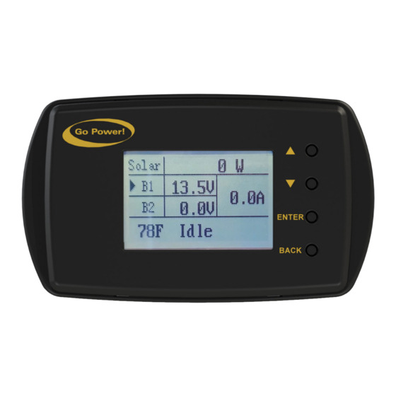
Page 5: Appearance
2. APPEARANCE Front View Side View NAME LCD Screen Back Button Enter Button Down Button Up Button RJ12 Connectors gpelectric.com | [page 5]... -
Page 6: User Interfaces
3. USER INTERFACE STARTUP SPLASH SCREENS The following splash screens are displayed when the controller/remote display are first powered on. [MENU 1]: RVC-DISPLAY Establishing connection with the controller (this interface only exists for a very short time) [MENU 2]: RVC-DISPLAY startup, displays Go Power! 1. - Page 7 USER INTERFACE 3. Setting Screens The settings screens are used to view and edit settings and also to issue commands to the controller. The following steps can be used to get to the settings screens shown as [MENU9] to [MENU16] and navigate through them. A detailed explanation of each setting parameter is included in a table in section 4 below.
- Page 8 USER INTERFACE The following steps can be used to get to the settings screens shown as [MENU9] to [MENU16] and navigate through them.” [page 8] | gpelectric.com...
-
Page 9: Status, Settings And Commands
4. STATUS, SETTINGS AND COMMANDS The following table lists all of the status parameters, settings and commands that are available on the controller via the remote display and the Go Power! Connect mobile application. The actual value displayed may be prefaced with “Batt1” or “Batt2” if the remote display is connected to a GP-RVC-MPPT-30 controller since these are dual bank controllers. - Page 10 STATUS, SETTINGS AND COMMANDS Since each type of battery is charged and maintained differently, the battery type must be set to match the battery connected to the Flooded, GEL, controller. Type Battery Type AGM, Li, USER (Custom) When the battery type is changed the fol- lowing characteristics will change according to the battery type.
- Page 11 STATUS, SETTINGS AND COMMANDS The absorption duration is the amount of Absorption time the bulk-absorption voltage will be BST Time 120min 0 - 600min Duration applied to the battery during the absorption stage. The equalize interval is the frequency at Equalization Equ Int 0days...
-
Page 12: Charge States & Faults
5. CHARGE STATES AND FAULTS The main screen has a section at the bottom (indicated in the images below) to indicate either charge state if the controller is charging normally or fault information if the controller has entered a fault state. All of the possible charge states and fault states are listed in the table below. -
Page 13: Commands
6. COMMANDS FORCE CHARGE The force charge commands are used to force the solar controller into either bulk charging or float charging. This can be done on both the GP-RVC-MPPT-10 and the GP-RVC-MPPT-30. On the GP-RVC-MPPT-30 the force charge commands give the option to force charge either battery so, for example, if Bat1 is connected to the house battery and Bat2 is connected to the starter battery and both batteries are low the force charge command can be used to force the charger into charging Bat2 instead of it’s usual priority, Bat1. -
Page 14: Installation
7. INSTALLATION The GP-RVC-R is intended to be mounted to an interrior wall so the status of the solar controller can be viewed. Tools and Materials Needed • Philips screw driver • Drill • 1” diameter drill bit or hole saw Installation Steps THIS REMOTE DISPLAY CAN BE MOUNTED USING THE FOLLOWING STEPS. -
Page 15: Bluetooth Wireless Technology
8. BLUETOOTH WIRELESS TECHNOLOGY ® The GP-RVC-R comes with Bluetooth wireless technology for live status monitoring and settings configuration on mobile ® devices. It works together with the Go Power! Connect App, available for both Android and iOS devices. Download and install the Go Power! Connect app, which is available on the Google Play store for Android devices and the App Store for iOS devices. - Page 16 BLUETOOTH WIRELESS TECHNOLOGY ® SOC INDICATION SYMBOL BATTERY VOLTAGE ≥ 12.8 / 25.6 V ≥ 12.6 / 25.2 V to 12.8 / 25.6 V ≥ 11.8 / 23.6 V to 12.6 / 25.2 V ≥ 11.0 / 22.0 V to 11.8 / 23.6 V ≤...
-
Page 17: Limited Warranty
9. LIMITED WARRANTY Go Power! warrants the GP-RVC-R for a period of five (5) years from the date of shipment from its factory. This warranty is valid against defects in materials and workmanship for the five (5) year warranty period. It is not valid against defects resulting from, but not limited to: •... -
Page 19: Mounting Template
10. MOUNTING TEMPLATE 1.0in 25.4mm 4.1in 105mm UNLESS OTHERWISE SPECIFIED PROPRIETARY DO NOT SCALE DRAWING THE INFORMATION CONTAINED IN THIS DRAWING IS THE SOLE INTERPRET DIMENSIONS AND TOLERANCES PER ASME Y14.100-2000 PROPERTY OF VALTERRA TOLERANCES APPLY AS SHOWN BELOW PRODUCTS, LCC. (GO POWER!). DECIMALS SURF FINISH ANGLES... - Page 20 © 2021 Go Power! Worldwide Technical Support and Product Information gpelectric.com Go Power! | Dometic 201-710 Redbrick Street Victoria, BC, V8T 5J3 Tel: 1.866.247.6527 GP-RVC-R Manual...
Need help?
Do you have a question about the Go Power! GP-RVC-R and is the answer not in the manual?
Questions and answers
We just purchased a 2025 Aligner Ranger 12. It has a 30 amp plug in for shore power, one HD24-DP Interstate battery, propane, and solar capability which is not currently being used. The unit has various Dometic equipment in it. I want to monitor my battery power/use/condition. What model Dometic Go Power do I need? Thanks.