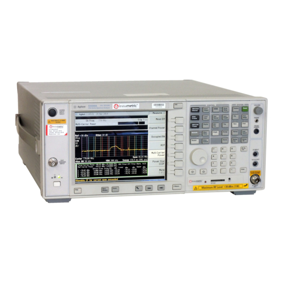
Agilent Technologies PSA Series Installation Note
Spectrum analyzers option 426 gated sweep hardware retrofit kit
Hide thumbs
Also See for PSA Series:
- Service manual (436 pages) ,
- User and programming manual (434 pages) ,
- Manual (382 pages)
Summary of Contents for Agilent Technologies PSA Series
- Page 1 Installation Note Agilent Technologies PSA Series Spectrum Analyzers Option 426 Gated Sweep Hardware Retrofit Kit Part Number E4440-90305 Supersedes: E4440-90271 Printed in USA June 2005...
- Page 2 The information contained in this document is subject to change without notice. Agilent Technologies makes no warranty of any kind with regard to this material, including but not limited to, the implied warranties of merchantability and fitness for a particular purpose.
- Page 3 Option 426 Gated Sweep Hardware Retrofit Kit Option 426 Gated Sweep Hardware Retrofit Kit Products Affected: PSA E4440A PSA E4443A PSA E4445A PSA E4446A PSA E4448A Serial Numbers: US0000 / US4251 MY0000 / MY4328 To Be Performed By: (X) Agilent Service Center (X) Personnel Qualified by Agilent ( ) Customer Estimated Installation Time:...
- Page 4 Calibration software. Latest software information and downloads available at http://www.agilent.com/find/calibrationsoftware Test equipment supported by the calibration software. PSA Series Spectrum Analyzer and Service Guide. This manual is available as part of the E4440AU, E4443AU, or E4445AU Option OBW kits. Microsoft Windows based personnel computer Windows 2000, Windows XP Professional.
-
Page 5: Installation Procedure
Installation Procedure Installation Procedure Remove the Outer Case CAUTION If the instrument is placed on its face during any of the following procedures, be sure to use a soft surface or soft cloth to avoid damage to the front panel, keys, or input connector. 1. - Page 6 Installation Procedure Remove the Top Brace 6. Refer to Figure 2. Use the T-10 driver to remove the top screws (3) (one screw is under the security label), and the side screws (2) attaching the top brace (1) to the deck.
- Page 7 Installation Procedure Remove the A12 LO Synthesizer Assembly 8. Refer to Figure 3. Remove cable W24. 9. Remove the cable hold down wire (single screw), and the two screws attaching the synthesizer assembly to the midweb and deck. 10.Pull up on the ejector tab to unseat the board from the motherboard connector, then slide the board up to remove it from the deck.
- Page 8 Installation Procedure Replace the A12A1 LO Synth Board (part of A12 LO Synthesizer assembly) 11.Remove the cables from J3 and J4 on the A12 assembly at the location shown in Figure Figure 4 LO Synthesizer Assembly 12.Turn the A12 over and remove the screws and A12 LO Synth Bottom Shield as shown Figure Figure 5 A12A1 LO Synth Board...
- Page 9 Replacement Kit except for the following: Reset the Calibration Constants for the A12A1 LO Synthesizer Board The PSA Series Performance Tests and Adjustment Software, A.02.00 and above, must be used to reset the calibration constants on the replacement A12A1 LO Synthesizer board you just installed.
- Page 10 1. Write “Gated Sweep” on the blank label using a fine point permanent marker. 2. Attach label to the right bottom corner of rear dress panel of the instrument. Assistance For assistance, contact the nearest Agilent Technologies Sales and Service Office. To find your local Agilent office access the following URL: http://www.agilent.com/find/assist...


