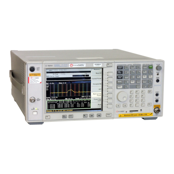
Agilent Technologies PSA Series Installation Note
Agilent spectrum analyzers option 124 y-axis video output retrofit kit
Hide thumbs
Also See for PSA Series:
- Service manual (436 pages) ,
- User and programming manual (434 pages) ,
- Manual (382 pages)
Summary of Contents for Agilent Technologies PSA Series
- Page 1 Installation Note Agilent PSA Series Spectrum Analyzers Option 124 Y-Axis Video Output Retrofit Kit Part Number E4440-90255 Printed in USA August 2004...
- Page 2 The information contained in this document is subject to change without notice. Agilent Technologies makes no warranty of any kind with regard to this material, including but not limited to, the implied warranties of merchantability and fitness for a particular purpose.
- Page 3 Y-Axis Video Output Installation Kit Y-Axis Video Output Installation Kit Products Affected: PSA E4440A PSA E4443A PSA E4445A PSA E4446A PSA E4448A Serial Numbers: US4430 / US9999 MY4430 / MY999999 For instruments that do not have Option 122. To Be Performed By: (X) Agilent Service Center (X) Personnel Qualified by Agilent ( ) Customer...
- Page 4 PSA Series Performance Tests and Adjustment Software, E.01.00 or later Test equipment supported by the PSA Series Performance Tests and Adjustment Software. PSA Series Spectrum Analyzer and Service Guide. This manual is available as part of the E4440AU, E4443AU, or E4445AU Option OBW kits. Microsoft Windows based personnel computer Windows 2000, Windows XP Professional Firmware A.0 6.00 or later.
-
Page 5: Installation Procedure
Installation Procedure Installation Procedure Install Firmware A.06.00 or Greater if Needed 1. Press . The Firmware Revision needs to be A.06.00 or later. System, More, Show System 2. If the firmware needs to be updated, do the following: Download the PSA Update Program and the PSA Firmware Procedure from http://www.agilent.com/find/psa_firmware. - Page 6 Installation Procedure Figure 1 Instrument Outer Case Removal Installation Note E4440-90255...
- Page 7 Installation Procedure Remove the Top Brace 1. Refer to Figure 2. Use the T-10 driver to remove the top screws (3) (one screw is under the security label), and the side screws (2) attaching the top brace (1) to the deck.
- Page 8 Installation Procedure Installing the Retrofit Kit 1. Refer to Figure 3. Locate the A7 Digital IF Assembly. It is in the forth card slot from the power supply. This assembly will have casting covers covering the PC board. Figure 3 A7 Digital IF Assembly 2.
- Page 9 Installation Procedure Replace the Top Brace and Outer Case 1. Refer to Figure 2. Carefully position the top brace on the deck. The alignment pin at the center of the web/fan assembly must mate with the alignment hole on the top brace.
- Page 10 Installation Procedure Installing the Option Designator and License Keyword NOTE The option designator 124 and the license keyword must be entered into instrument memory in addition to the correct firmware before the hardware will function. 1. Follow the directions on the Option Upgrade Entitlement Certificate included in the kit.
- Page 11 Installation Procedure Verify the Option Connect a voltmeter to the rear panel Video Out port of the PSA. Set the voltmeter to measure DC volts. 1. With the instrument is spectrum analysis mode, Preset the instrument. 2. Select the internal amplitude reference by pressing , and Input/Output Input Port...
- Page 12 Performing only these tests does not guarantee the instrument meets specifications. There are no adjustments on the Digital IF assembly. This procedure requires the use of the PSA Series Performance Tests NOTE and Adjustment Software.


