Table of Contents
Advertisement
Advertisement
Table of Contents

Related Manuals for ESD EtherCAN/2


Summary of Contents for ESD EtherCAN/2
- Page 1 Product C.2051.02 EtherCAN/2 Hardware Manual • Doc.-No.: C.2051.21 / Rev.2.0 Page 1 of 75 esd electronics gmbh Vahrenwalder Str. 207 • 30165 Hannover • Germany http://www.esd.eu Phone: +49 (0) 511 3 72 98-0 • Fax: +49 (0) 511 3 72 98-68...
- Page 2 design.
- Page 3 New chapter “References” EU Declaration of Conformity updated Order information revised 7./8. Chapter updated 2021-10-27 EU Declaration of Conformity updated Technical details are subject to change without further notice. EtherCAN/2 Hardware Manual • Doc.-No.: C.2051.21 / Rev. 2.0 Page 3 of 75...
- Page 4 This NOTICE statement contains the general mandatory sign and gives information that must be heeded and complied with for a safe use. INFORMATION INFORMATION Notes to point out something important or useful. Page 4 of 75 Hardware Manual • Doc.-No.: C.2051.21 / Rev. 2.0 EtherCAN/2...
-
Page 5: Safety Instructions
● When working with the EtherCAN/2 follow the instructions below and read the manual carefully to protect yourself from injury and the EtherCAN/2 from damage. ● Do not use damaged or defective cables to connect the EtherCAN/2 and follow the CAN wiring hints in chapter: "Correct Wiring of Electrically Isolated CAN Networks". -
Page 6: Table Of Contents
Table of Contents Safety Instructions........................... 5 1 Overview............................8 Description of the EtherCAN/2....................8 Starting Up..........................10 Software Configuration.......................11 Configuration of the IP Address....................11 3.1.1 Configuration via DHCP....................11 3.1.1.1 Using a Hostname Instead of the IP Address............12 3.1.2 Determining IP Address via UPnP................12... - Page 7 8.1 Termination.......................... 64 Electrical Grounding......................65 Short Circuit in CAN Wiring....................65 CAN_H/CAN_L-Voltage ......................65 CAN Transceiver Resistance Test..................66 Support by esd........................66 Appendix InRailBus (Option)......................67 Order Information InRailBus Accessories................67 Connector Assignment 24V and CAN via InRailBus (Option)..........68 Using InRailBus (Option).....................69 9.3.1 Installation of the Module Using InRailBus Connector..........69...
-
Page 8: Overview
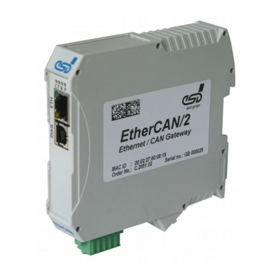
24 V= Figure 1: Block circuit diagram The EtherCAN/2 is an Ethernet-CAN-Gateway equipped with an ARM9 processor, which controls the data transfer between CAN and Ethernet. The Ethernet interface is suitable for 10 Mbit/s and 100 Mbit/s networks and can be connected via an RJ45-socket. - Page 9 Read chapter “Starting Up” on page 10, before you start with the installation of the hardware! Please refer to page 53 for signal assignment of the connectors. EtherCAN/2 Hardware Manual • Doc.-No.: C.2051.21 / Rev. 2.0 Page 9 of 75...
-
Page 10: Starting Up
All current circuits which are connected to the device have to be sufficiently protected against hazardous voltage (SELV according to EN 60950-1) before you start with the installation. Mount and wire the EtherCAN/2 module (power supply voltage, CAN, Ethernet). Please remember that the CAN bus has to be terminated at both ends. -
Page 11: Software Configuration
3.1 Configuration of the IP Address First a valid IP address has to be assigned to the EtherCAN/2. An IP address is an unique address for a device, that communicates in a TCP/IP network. -
Page 12: Using A Hostname Instead Of The Ip Address
3.1.2 Determining IP Address via UPnP In the state of delivery the EtherCAN/2 furthermore operates as an UPnP-device. The IP address of the EtherCAN/2 can not be changed by this, but generally you can easily get to the web based configuration. - Page 13 The corresponding settings are generally enabled by default here, and the symbol of the EtherCAN/2 is shown in the window My Network Places (without a note as in Windows XP). A double click to the icon of the device automatically opens the configuration page in the standard web-browser.
-
Page 14: Configuration Via Esdcp
To delete the entries of the Device List click the button Clear Device List . If no DHCP could have been been found and the EtherCAN/2 thus has got an IP address in the range of 169.254.x.x, the PC has to be configured accordingly (only once, for the configuration of the EtherCAN/2). - Page 15 Enter the IP address in the input field in the column Configured Value. Enter the Netmask in the same manner. Activate the check-box Reset Device for a reboot of the EtherCAN/2 after acknowledgement of the entry, because the changes are not transferred until the device is rebooted.
-
Page 16: Web Based Configuration
A menu is shown on the left side of this program window. In the menu item Overview the module specific details of the EtherCAN/2 are shown. Under Gateway details you find firmware revision, hardware revision, order number and serial number. -
Page 17: Configuration
User name and password can be adapted. Usage of special characters and space characters is not allowed. Pay attention to case sensitivity. Clicking the button Submit saves the changed data in a non-volatile memory of the EtherCAN/2 module. After a reboot the data will become active. -
Page 18: Network Settings
The menu item Network Settings contains an overview of the configured values for: ● TCP/IP ● SMTP ● Time Server ● SNMP ● esdcp Figure 7: Network configuration Page 18 of 75 Hardware Manual • Doc.-No.: C.2051.21 / Rev. 2.0 EtherCAN/2... - Page 19 A domain name can be entered in the input box Domain. TCP/IP Default Parameters At the first time starting up of the EtherCAN/2 the check box Use DHCP is enabled. Thus the IP address is per default assigned via the DHCP-Server.
- Page 20 SNMP (Simple Network Management Protocol) is a protocol to control and monitor various network devices, e.g. router, printer etc. The EtherCAN/2 gateway provides - besides various standard data as e.g. “Uptime” - the data of the CAN Statistics (see page 43).
- Page 21 These data can then be evaluated further by means of corresponding tools (SNMP manager). An appropriate “.mib” file for this is available in the installation directory of the host-driver. The SNMP agent of the EtherCAN/2 gateway supports the versions 1 and 2c of the SNMP protocol. The community string is “public”.
-
Page 22: Remote Logging
Use the check boxes Log Errors, Log Warnings and Log Infos to configure which kind of event should be transmitted as e-mail. Click the button Submit to save the changed data in a non-volatile memory of the EtherCAN/2 module. After a reboot the data is enabled. -
Page 23: Firmware Update
Software Configuration 3.2.2.4 Firmware Update For an update of the firmware of the EtherCAN/2 click the menu item Firmware Update in the program window. Figure 14: Firmware update The upload of the file is done by means of the web browser. Enter the file name, or click the button Choose... - Page 24 Software Configuration Figure 15: Firmware update protocol (example) Wait until the protocol about the update is completely finished. The system will reboot automatically. Page 24 of 75 Hardware Manual • Doc.-No.: C.2051.21 / Rev. 2.0 EtherCAN/2...
-
Page 25: Can Bridge
On this page the “CAN Bridge” functionality of the EtherCAN/2 is configured. This one allows to connect two CAN networks via Ethernet. To achieve this, this configuration page is used to set up two EtherCAN/2 modules so they are able to connect to each other to exchange the CAN messages. -
Page 26: Short Description/Quick Start
Select “Clear and enable all IDs” under “CAN 29 bit filter” and “Clear and enable all IDs” under “CAN 11 bit filter” 4. Restart the device in bridge mode Button “Restart CAN Bridge” • Page 26 of 75 Hardware Manual • Doc.-No.: C.2051.21 / Rev. 2.0 EtherCAN/2... - Page 27 Software Configuration Figure 17: CAN Bridge configuration page EtherCAN/2 Hardware Manual • Doc.-No.: C.2051.21 / Rev. 2.0 Page 27 of 75...
-
Page 28: Important Notes
NOTICE If the EtherCAN/2 is used e.g. as CAN interface for a PC or in bridge mode at the same time, it has to be ensured that no conflicts arise. (Especially different CAN baud rates must not be set at the same time) Page 28 of 75 Hardware Manual •... -
Page 29: Miscellaneous
Figure 19: CAN Bridge – “Configuration file” Upload new configuration • Used to upload a bridge configuration file to the EtherCAN/2. By the “Browse” button (or ◦ “Choose” etc., depends on browser/language) the file is selected, the “Upload” button transfers it then. This will overwrite all current settings. For details about the configuration file format see 3.2.2.5.6... -
Page 30: Edit Configuration Online
All changes will be transferred to the EtherCAN/2 only with usage of the “Submit” button, i.e. when leaving the page or triggering any other action, such as a bridge restart or configuration file upload, all inputs made here will be lost. - Page 31 29 bit CAN frames Clear and disable all IDs ◦ Deletes all mapping entries and resets “Acceptance code/mask” to receive/forward ▪ no 29 bit CAN frames EtherCAN/2 Hardware Manual • Doc.-No.: C.2051.21 / Rev. 2.0 Page 31 of 75...
- Page 32 Rejects all changes made since last loading the page or submitting changes and ◦ restores the previous values Submit • Transmits all changes to the EtherCAN/2 ◦ Page 32 of 75 Hardware Manual • Doc.-No.: C.2051.21 / Rev. 2.0 EtherCAN/2...
-
Page 33: Configuration File
The receive ID is always interpreted as 11 bit ID, the send ID has to use bit 29 as marker. (So this sample line sends the 11 Bit ID 0x100 as 29 Bit ID 0x00000101) EtherCAN/2 Hardware Manual • Doc.-No.: C.2051.21 / Rev. 2.0 Page 33 of 75... - Page 34 Software Configuration Sample file Line # esd EtherCAN/2 CAN Bridge configuration file. remote_ip 10.0.1.2 can_baudrate 0x00000000 can_29bit_acceptmask 0x000000ff can_29bit_acceptcode 0x00000100 can_29bit_map 0x00000120 0x00000100 can_29bit_map 0x00000121 0x20000101 can_11bit_enable 2047 can_11bit_map 0x00000100 0x20000100 Figure 24: CAN Bridge – Sample configuration file Line 6: (remote_ip) •...
-
Page 35: Can Tcp Client
NOTICE If the EtherCAN/2 is used e.g. as CAN interface for a PC or in bridge mode at the same time, it has to be ensured that no conflicts arise. (Especially different CAN baud rates must not be set at the same time) Figure 25: CAN TCP Client –... - Page 36 If this is enabled, then, while setting the baud rate, it's also chosen that the CAN ▪ controller shall work in “listen-only mode”, i.e. the EtherCAN/2 acts as a passive bus member and does not even send an acknowledge. (Keep in mind that when there's only one active bus member, it will retry sent frames for many times due to missing acknowledgment –...
-
Page 37: Protocol
All values within the data are, unless otherwise stated, transmitted in “network byte order”, i.e. “Big- endian”. When the connection is established the EtherCAN/2 starts with sending its version information, unasked – the server has to do that, too, else the EtherCAN/2 won't accept commands from the server. Command (ASCII) - Page 38 The 4 bytes refer to the “uint32_t” value that is used internally for the canSetBaudrate() ◦ function, see NTCAN API manual for details. (The “NTCAN_AUTOBAUD” feature is currently not supported by the EtherCAN/2) Change baud rate reply • The first 4 bytes are the same that were sent with “Change baud rate”, the other 4 bytes ◦...
-
Page 39: Version Information Struct
255 frames were lost this value is still set to 255) msg_lost Lost frames usually occur when the EtherCAN/2 failed to send them to the TCP connection in time, i.e. when the connection is too slow or the server does not read them fast enough from its client socket. -
Page 40: Websocket Server
Figure 26: WebSocket server – configuration page NOTICE If the EtherCAN/2 is used e.g. as CAN interface for a PC or in bridge mode at the same time, it has to be ensured that no conflicts arise. (Especially different CAN baud rates... - Page 41 Software Configuration „Upload new server files archive“ • With this the files the WebSocket server shall deliver are transferred to the EtherCAN/2. ◦ They must be within a “.zip” file. The upload of such a file deletes all existing files. A re-download of an archive from the EtherCAN/2 is not possible.
-
Page 42: Reboot
The Events Log will be cleared after reboot. Furthermore the web server will be shut down and all links of the gateway clients/CAN Bridge will be disconnected. Page 42 of 75 Hardware Manual • Doc.-No.: C.2051.21 / Rev. 2.0 EtherCAN/2... -
Page 43: Status
To view the status of the CAN bus click the menu item CAN in the program window. Figure 28: Status CAN The values shown are also provided via SNMP (see page 20) and can be evaluated by means of additional tools. EtherCAN/2 Hardware Manual • Doc.-No.: C.2051.21 / Rev. 2.0 Page 43 of 75... -
Page 44: Bridge
“Remote RX Lost”: The number of CAN frames the remote side could not receive from its local CAN interface. (Under some circumstances the actual value can be higher than displayed here) Page 44 of 75 Hardware Manual • Doc.-No.: C.2051.21 / Rev. 2.0 EtherCAN/2... -
Page 45: Ethernet
The Ethernet status can be displayed by choosing the menu item Ethernet. On the Ethernet page the current transmission speed (10/100 Mbit/s), the communication mode (half/full duplex) and the MAC-ID of the EtherCAN/2 module are displayed among a number of statistical parameters of the Ethernet link. -
Page 46: Connected Clients
As the total number of connected clients is fixed, the number of table lines is fixed, too. Lines which contain clients that are not connected (or no longer connected) are displayed in a grey font. For further information about ELLSI see ELLSI software-manual: ELLSI_Software_Manual.pdf. Page 46 of 75 Hardware Manual • Doc.-No.: C.2051.21 / Rev. 2.0 EtherCAN/2... -
Page 47: Alarms And Events
For this window click the menu item Events. This page shows the alarms and events from the start up of the EtherCAN/2. The events are classified depending on the severity into the categories Error, Warning and Info. The list will be deleted at every reboot. -
Page 48: Leds
Ethernet activity (reception of Ethernet data) no Ethernet connection Link yellow Link Status Ethernet (link to server or hub) Table 2: Display function of ETH LEDs (RJ45-socket) Page 48 of 75 Hardware Manual • Doc.-No.: C.2051.21 / Rev. 2.0 EtherCAN/2... - Page 49 Table 3: Display function of LEDs During the boot up phase all LEDs (C, E, R, P) are additionally set to “on” for 0.5 seconds. EtherCAN/2 Hardware Manual • Doc.-No.: C.2051.21 / Rev. 2.0 Page 49 of 75...
-
Page 50: Technical Data
Table 4: General technical data 5.2 Microprocessor and Memory ARM9-Processor, 200 MHz, AT91SAM9263 Data Flash 1 MB NAND Flash 256 MB SDRAM 32 MB Table 5: Microprocessor and Memory Page 50 of 75 Hardware Manual • Doc.-No.: C.2051.21 / Rev. 2.0 EtherCAN/2... -
Page 51: Can Interface
5.5 DIAG, Serial Interface via USB Interface Type USB, for manufacturing purposes only USB specification USB 2.0 Full Speed (12 Mbit/s) Connector DIAG (X4), USB-connector type-B Table 8: Data of the DIAG interface EtherCAN/2 Hardware Manual • Doc.-No.: C.2051.21 / Rev. 2.0 Page 51 of 75... -
Page 52: Software
“3rd Party Licensor Notice” as part of the product documentation. License information esd provides the complete bootloader-source code on request. esd strives to restore all changes on the bootloader into the official sources. The homepage of the U-Boot project is: http://www.denx.de/wiki/U-Boot. -
Page 53: Interfaces And Connector Assignments
The assignment of the 9- pin DSUB-connector is designed according to CiA DS-102. The assignment of the 5-pin Mini- COMBICON is designed according to CiA DR-303 Part 1 EtherCAN/2 Hardware Manual • Doc.-No.: C.2051.21 / Rev. 2.0 Page 53 of 75... -
Page 54: Power Supply Voltage
Phoenix Contact order No.: 19 21 90 0 (included in the scope of delivery) For conductor connection and conductor cross section see page 56. Pin Position: Pin Assignment: Labelling of the EtherCAN/2 Do not Do not Signal connect! connect! (GND) (+24 V) Please refer to the connecting diagram page 9. -
Page 55: Ethernet 100Base-Tx (Ieee 802.3)
Permissible cables: To ensure function in networks with up to 100 MBit/s cables of Cat. 5e or better have to be used. To ensure the EC Conformity cables with shielding SF/UTP or better have to be used. EtherCAN/2 Hardware Manual • Doc.-No.: C.2051.21 / Rev. 2.0 Page 55 of 75... -
Page 56: Conductor Connection/Conductor Cross Sections
Minimum AWG according to UL/cUL Maximum AWG according to UL/cUL Technical Data from Phoenix Contact website, printed circuit board connector, plug component Page 56 of 75 Hardware Manual • Doc.-No.: C.2051.21 / Rev. 2.0 EtherCAN/2... -
Page 57: Correct Wiring Electrically Isolated Can Networks
Therefore the practical maximum number of nodes, bus length and stub length are typically much lower. esd has concentrated her recommendations concerning CAN wiring on the specifications of the ISO 11898-2. Thus this wiring hints forgoes to describe the special features of the derived standards CANopen, ARINC825, DeviceNet and NMEA2000. -
Page 58: Light Industrial Environment (Single Twisted Pair Cable)
7.2.1 General Rules NOTICE esd grants the EU Conformity of the product, if the CAN wiring is carried out with at least single shielded single twisted pair cables that match the requirements of ISO 11898-2. Single shielded double twisted pair cable wiring as described in chapter 7.3. ensures the EU Conformity as well. -
Page 59: Cabling
9-pin DSUB-termination connectors with integrated termination resistor and pin contacts ● and socket contacts are available from esd (order no. C.1303.01). DSUB termination connectors with pin contacts (order no. C.1302.01) or socket contacts ● (order no. C.1301.01) and additional functional earth contact are available, if CAN termination and grounding of CAN_GND is required. -
Page 60: Heavy Industrial Environment (Double Twisted Pair Cable)
CAN_L CAN_GND wire shield n.c. n.c. connector case connector case Shield n.c. = not connected earth (FE) Figure 36: CAN wiring for heavy industrial environment Page 60 of 75 Hardware Manual • Doc.-No.: C.2051.21 / Rev. 2.0 EtherCAN/2... -
Page 61: Device Cabling
CAN bus line via short cable stubs. This is normally realised by so called T- connectors. When using esd's CAN-T-Connector (order no.: C.1311.03) it should be noted that the shield potential of the conductive DSUB housing is not looped through this T- Connector type. -
Page 62: Electrical Grounding
5000 Table 9: Recommended cable lengths at typical bit rates (with esd-CAN interfaces) Optical couplers are delaying the CAN signals. esd modules typically reach a wire length of ● 37 m at 1 Mbit/s within a proper terminated CAN network without impedance disturbances like e.g. -
Page 63: Examples For Can Cables
Correct Wiring Electrically Isolated CAN Networks 7.6 Examples for CAN Cables esd recommends the following two-wire and four-wire cable types for CAN network design. These cable types are used by esd for ready-made CAN cables, too. 7.6.1 Cable for light industrial Environment Applications (Two-Wire) -
Page 64: Can Troubleshooting Guide
- there are no open circuits in CAN_H or CAN_L wiring - your bus system has two terminating resistors (one at each end) and that they are 120 Ω each. Page 64 of 75 Hardware Manual • Doc.-No.: C.2051.21 / Rev. 2.0 EtherCAN/2... -
Page 65: Electrical Grounding
(see figure at previous page). 4. Measure the DC voltage between CAN_L and CAN_GND (see figure at previous page). Normally the voltage should be between 2.0 V and 3.0 V. EtherCAN/2 Hardware Manual • Doc.-No.: C.2051.21 / Rev. 2.0 Page 65 of 75... -
Page 66: Can Transceiver Resistance Test
If you have executed the fault diagnostic steps of this troubleshooting guide and you even can not find a solution for your problem our support department will be able to assist. Please contact our support via email at support@esd.eu or by phone +49-511-37298-130. Page 66 of 75 Hardware Manual •... -
Page 67: Appendix Inrailbus (Option)
Terminal plug of the CBX-InRailBus for the CAN-CBX-TBUS- connection of the +24V power supply voltage C.3000.03 Connection adapter and the CAN-Interface Male type Table 10: Order Information EtherCAN/2 Hardware Manual • Doc.-No.: C.2051.21 / Rev. 2.0 Page 67 of 75... -
Page 68: Connector Assignment 24V And Can Via Inrailbus (Option)
CAN_GND ... reference potential of the local CAN-Physical layers P24... power supply voltage +24 V M24... reference potential FE... functional earth contact (EMC) (connected to mounting rail potential) Page 68 of 75 Hardware Manual • Doc.-No.: C.2051.21 / Rev. 2.0 EtherCAN/2... -
Page 69: Using Inrailbus (Option)
INFORMATION This chapter describes the installation of the module using InRailBus for CAN-CBX- modules. For the EtherCAN/2 module the following points apply accordingly . 9.3.1 Installation of the Module Using InRailBus Connector If the CAN bus signals and the power supply voltage shall be fed via the InRailBus, please proceed... -
Page 70: Connecting Power Supply And Can Signals To Cbx-Inrailbus
Plug the terminal plug into the socket on the right of the mounting-rail bus connector of the InRailBus, as described in Figure 44. Then connect the CAN interface and the power supply voltage via the terminal plug. Page 70 of 75 Hardware Manual • Doc.-No.: C.2051.21 / Rev. 2.0 EtherCAN/2... -
Page 71: Connection Of The Power Supply Voltage
A bus termination must be connected to the CAN connector of the CAN-CBX module at the end of the CBX-InRailBus (see Figure 46), if the CAN bus ends there. EtherCAN/2 Hardware Manual • Doc.-No.: C.2051.21 / Rev. 2.0 Page 71 of 75... -
Page 72: Remove The Can-Cbx Module From Inrailbus
INFORMATION It is possible to remove individual devices from the whole without interrupting the InRailBus connection, because the contact chain will not be interrupted. Page 72 of 75 Hardware Manual • Doc.-No.: C.2051.21 / Rev. 2.0 EtherCAN/2... -
Page 73: References
References 10 References [1] esd electronic system design gmbh, Hannover; NTCAN-API - Part 2: Installation Guide, Rev. 4.2, 2015-01-26 [2] esd electronic system design gmbh, Hannover; NTCAN-API - Part 1: Application Developpers Manual, Rev. 4.7, 2015-10-12 EtherCAN/2 Hardware Manual • Doc.-No.: C.2051.21 / Rev. 2.0... -
Page 74: Declaration Of Conformity
Declaration of Conformity 11 Declaration of Conformity Page 74 of 75 Hardware Manual • Doc.-No.: C.2051.21 / Rev. 2.0 EtherCAN/2... -
Page 75: Order Information
Table 11: Order information PDF Manuals Manuals are available in English and usually in German as well. For availability of English manuals see table below. Please download the manuals as PDF documents from our esd website www.esd.eu for free. Manuals Order No.
Need help?
Do you have a question about the EtherCAN/2 and is the answer not in the manual?
Questions and answers