Table of Contents
Advertisement
Quick Links
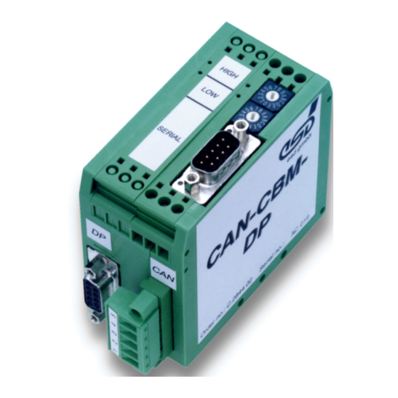
CAN-CBM-DP
Profibus-DP / CAN-Gateway
DN-CBM-DP
Profibus-DP / DeviceNet-Gateway
Hardware Manual
to Product C.2844.03/.05 and C.2846.02
CAN-CBM-DP / DN-CBM-DP
/
Page 1 of 45
Hardware-Manual • Doc.-No.: C.2844/6.21
Rev. 1.9
esd electronics gmbh
Vahrenwalder Str. 207 • 30165 Hannover • Germany
http://www.esd.eu
Phone: +49 (0) 511 3 72 98-0 • Fax: +49 (0) 511 3 72 98-68
Advertisement
Table of Contents

Subscribe to Our Youtube Channel
Related Manuals for ESD CAN-CBM-DP


Summary of Contents for ESD CAN-CBM-DP
- Page 1 CAN-CBM-DP Profibus-DP / CAN-Gateway DN-CBM-DP Profibus-DP / DeviceNet-Gateway Hardware Manual to Product C.2844.03/.05 and C.2846.02 CAN-CBM-DP / DN-CBM-DP Page 1 of 45 Hardware-Manual • Doc.-No.: C.2844/6.21 Rev. 1.9 esd electronics gmbh Vahrenwalder Str. 207 • 30165 Hannover • Germany http://www.esd.eu...
- Page 2 The information in this document has been carefully checked and is believed to be entirely reliable. esd makes no warranty of any kind with regard to the material in this document, and assumes no responsibility for any errors that may appear in this document. In particular descriptions and technical data specified in this document may not be constituted to be guaranteed product features in any legal sense.
- Page 3 Chapter “Conductor Cross Section” Chapter “Order Information” moved and revised Figure corrected, 100 resistor R126 inserted Description of shield potential inserted Technical details are subject to change without notice. CAN-CBM-DP / DN-CBM-DP Page 3 of 45 Hardware-Manual • Doc.-No.: C.2844/6.21 Rev. 1.9...
- Page 4 This NOTICE statement contains the general mandatory sign and gives information that must be heeded and complied with for a safe use. INFORMATION INFORMATION Notes to point out something important or useful. Page 4 of 45 CAN-CBM-DP / DN-CBM-DP Hardware-Manual • Doc.-No.: C.2844/6.21 Rev. 1.9...
- Page 5 The installation and commissioning of the product may only be carried out by qualified personnel, which is authorized to put devices, systems and electric circuits into operation according to the applicable national standards of safety engineering. CAN-CBM-DP / DN-CBM-DP Page 5 of 45 Hardware-Manual • Doc.-No.: C.2844/6.21...
- Page 6 The intended use of the CAN-CBM-DP is the operation as PROFIBUS-DP/CAN-Gateway. The intended use of the DN-CBM-DP is the operation as PROFIBUS-DP/DN-Gateway The esd guarantee does not cover damages which result from improper use, usage not in accordance with regulations or disregard of safety instructions and warnings.
-
Page 7: Table Of Contents
1.1 Module Description CAN-CBM-DP ........9... - Page 8 6.6 Support by esd ........
-
Page 9: Overview
Figure 1: Block-circuit diagram of the CAN-CBM-DP module By means of the module CAN-CBM-DP any Profibus-DP master can be connected to a CAN network. The DP/CAN gateway acts like a slave I/O component on the DP-bus, with a total of up to 300 bytes input and output data. -
Page 10: Module Description Dn-Cbm-Dp
The DN-CBM-DP can be configured with a PROFIBUS-tool as for example the SIMATIC Manager S7 or the TIA Portal. The module has a serial interface (default: RS-232) for servicing and configuration. It is connected by means of a male DSUB9. Page 10 of 45 CAN-CBM-DP / DN-CBM-DP Hardware-Manual • Doc.-No.: C.2844/6.21 Rev. 1.9... -
Page 11: Front View With Connectors And Coding Switches
Figure 4: Internal module structure with PCB designations and connector names (Figure without connector for supply voltage) INFORMATION The LEDs are described in detail in the software manuals of the modules. CAN-CBM-DP / DN-CBM-DP Page 11 of 45 Hardware-Manual • Doc.-No.: C.2844/6.21 Rev. 1.9... -
Page 12: Summary Of Technical Data
(including hat rail mounting and jutted out connectors DSUB9, (W x H x D) without CAN/DeviceNet connectors) Weight approx. 200 g Table 1: General data of the CAN-CBM-DP and DN-CBM-DP Page 12 of 45 CAN-CBM-DP / DN-CBM-DP Hardware-Manual • Doc.-No.: C.2844/6.21 Rev. 1.9... -
Page 13: Microcontroller Circuit
Connection 5-pin Phoenix Contact connector MSTB2.5/5-5.08 CAN controller SJA1000,according to ISO 11898-1 (CAN 2.0A/B) Electrical insulation of CAN via optocouplers and DC/DC converters (CAN-CBM-DP) interface from other circuits Physical Layer CAN Physical Layer according to ISO 11898-2, (CAN-CBM-DP) transmission rate programmable from 10 kbit/s to 1 Mbit/s Physical Layer DeviceNet Physical Layer according to DeviceNet specification Rev. -
Page 14: Profibus-Dp Interface
Table 4: Data of Profibus-DP interface 1.4.5 Serial Interface Controller 68331 Standard: RS-232 Interface Options: RS-422, RS-485, TTY active/passive Connection 9-pin DSUB male Table 5: Data of serial interface Page 14 of 45 CAN-CBM-DP / DN-CBM-DP Hardware-Manual • Doc.-No.: C.2844/6.21 Rev. 1.9... -
Page 15: Hardware Installation
CAN or DeviceNet, PROFIBUS-DP). Please note that the CAN bus has to be terminated at both ends! esd offers special T-connectors and termination connectors for external termination. Additionally the CAN_GND signal has to be connected to earth at exactly one point in the CAN network. -
Page 16: Circuit Description
3.1 CAN/DeviceNet Circuit 3.1.1 Interface Circuit The CAN-CBM-DP module is equipped with an ISO 11898-compliant CAN interface, the DN-CBM- DP with a DeviceNet interface. The same connector in Combicon design is used for the two types, the assignment of the connector, however, differs. The following figures show both interfaces. - Page 17 Circuit Description Figure 6: Circuit of DeviceNet interface DN-CBM-DP CAN-CBM-DP / DN-CBM-DP Page 17 of 45 Hardware-Manual • Doc.-No.: C.2844/6.21 Rev. 1.9...
-
Page 18: Profibus-Dp Circuit
R126 is equipped from serial number IS..Figure 7: Circuit of Profibus-DP interface NOTICE The terminating resistors of the Profibus-DB networks have to be connected externally (see EN 50 170)! Page 18 of 45 CAN-CBM-DP / DN-CBM-DP Hardware-Manual • Doc.-No.: C.2844/6.21 Rev. 1.9... -
Page 19: Serial Interface
Bit rate (set value) Bit rate (actual value) [bit/s] [bit/s] 38,400 38,462 19,200 19,231 9,600 9,615 4,800 4,808 2,400 2,404 1,200 1,199 600.2 299.9 Table 6: Adjustable bit rates CAN-CBM-DP / DN-CBM-DP Page 19 of 45 Hardware-Manual • Doc.-No.: C.2844/6.21 Rev. 1.9... -
Page 20: Connection Of Various Serial Interfaces
The signal terms are exemplary for the connection of the CBM-DP as transmitter (terminal DTE). 3.3.2.1 The RS-232 Interface The input signals CTS, DSR and DCD are not evaluated by the CAN-CBM-DP and DN-CBM-DP! Figure 8: Connection diagram for RS-232 operation... - Page 21 In order to activate the terminating resistor network on the piggy-back, you have to connect pins 9 and 2 and pins 4 and 7 in the DSUB9 connector, for example. CAN-CBM-DP / DN-CBM-DP Page 21 of 45 Hardware-Manual • Doc.-No.: C.2844/6.21...
- Page 22 Circuit Description 3.3.2.4 The TTY(20 mA) Interface Figure 11: Connection diagram for TTY operation (passive) Figure 12: Connection diagram for TTY operation (active) Page 22 of 45 CAN-CBM-DP / DN-CBM-DP Hardware-Manual • Doc.-No.: C.2844/6.21 Rev. 1.9...
-
Page 23: Function Of Coding Switches
The CAN-CBM-DP/DN-CBM-DP is operated as a slave station whose addresses can be set in the range decimally from 3 to 124 or hexadecimally from 0x03 to 0xC7. If an address smaller than 3 is set, address 3 is valid. -
Page 24: Connector Assignments
Connector Assignments 4. Connector Assignments 4.1 CAN/DeviceNet (X400) 4.1.1 CAN-CBM-DP: CAN-Bus (X400, 5-pin Combicon Style) Device connector: Phoenix Contact MSTB 2,5/5-5,08 (male contacts) Cable connector: Phoenix Contact MSTB 2,5/ 5-STF-5,08.. with screw connections For conductor connection and conductor cross section see page 34. -
Page 25: Dn-Cbm-Dp: Devicenet (X400, 5-Pin Combicon Style)
= 24 V ± 4%) V-... Reference potential to V+ and CAN+/CAN- CAN+, CAN-... CAN-signal lines Shield... Connection of shield line (Shield signal is not connected locally on the DN- CBM-DP) CAN-CBM-DP / DN-CBM-DP Page 25 of 45 Hardware-Manual • Doc.-No.: C.2844/6.21 Rev. 1.9... -
Page 26: Profibus-Dp Interface (X100-Cbmpb, 9-Pin Dsub Female)
Control signal for repeater (‘Request To Send’) +5 V... Voltage supply for external terminating resistor networks (max. 50 mA) GND... Reference potential Shield... Shielding (connected with the case of the 9-pin DSUB, female) Page 26 of 45 CAN-CBM-DP / DN-CBM-DP Hardware-Manual • Doc.-No.: C.2844/6.21 Rev. 1.9... -
Page 27: Serial Interface (X100)
(output) (input) 9-pin DSUB male The signal name is indicated looked by the CAN-CBM-module. The input signals CTS, DSR and DCD are not evaluated by the CAN-CBM-DP / DN-CBM-DP! CAN-CBM-DP / DN-CBM-DP Page 27 of 45 Hardware-Manual • Doc.-No.: C.2844/6.21... - Page 28 DSUB female DSUB female 25-pole 9-pole 25 24 23 22 21 20 19 18 17 16 15 14 CAN-CBM-DP DN-CBM-DP (CTS) local signal names used at CBM module Page 28 of 45 CAN-CBM-DP / DN-CBM-DP Hardware-Manual • Doc.-No.: C.2844/6.21 Rev. 1.9...
-
Page 29: Rs-422 Interface (X100-Sio331, 9-Pin Dsub Male)
Connector Assignments 4.3.2 RS-422 Interface (X100-SIO331, 9-pin DSUB male) Pin Position: Pin Assignment: Signal Signal (output) (output) (input) (input) 9-pin DSUB male CAN-CBM-DP / DN-CBM-DP Page 29 of 45 Hardware-Manual • Doc.-No.: C.2844/6.21 Rev. 1.9... -
Page 30: Rs-485 Interface (X100-Sio331, 9-Pin Dsub Male)
... The signals Term+ and Term- are connected to a terminating resistor network on the PCB. In order to activate the connection, Term+ has to be connected to the Rx/Tx+ signal and Term- with the Rx/Tx- signal. Page 30 of 45 CAN-CBM-DP / DN-CBM-DP Hardware-Manual • Doc.-No.: C.2844/6.21 Rev. 1.9... -
Page 31: Tty-Passive Interface (X100-Sio331, 9-Pin Dsub Male)
Pin Position: Pin Assignment: Signal Signal (transmitter) (transmitter) (receiver) (receiver) 9-pin DSUB male Signals I2+ and I1+ are assigned, but are not required for operating this physical interface. CAN-CBM-DP / DN-CBM-DP Page 31 of 45 Hardware-Manual • Doc.-No.: C.2844/6.21 Rev. 1.9... -
Page 32: Tty-Active Interface (X100-Sio331, 9-Pin Dsub Male)
Pin Assignment: Signal Signal (transmitter) GNDA (transmitter) (receiver) GNDA (receiver) 9-pin DSUB male The GNDA signals have been assigned but are not required for operating this physical interface. Page 32 of 45 CAN-CBM-DP / DN-CBM-DP Hardware-Manual • Doc.-No.: C.2844/6.21 Rev. 1.9... -
Page 33: Voltage Supply (X101, Uegm)
It is not permissible to feed-through the supply voltage, i.e. To use one side as 24 V input and the other side as 24 V output in order to supply other devices! Figure 13: Voltage supply CAN-CBM-DP / DN-CBM-DP Page 33 of 45 Hardware-Manual • Doc.-No.: C.2844/6.21... -
Page 34: Conductor Connection/Conductor Cross Sections
TWIN ferrules with plastic sleeve, min. / max. Minimum AWG according to UL/CUL Maximum AWG according to UL/CUL Technical Data from Phoenix Contact website printed circuit board connector, plug component Page 34 of 45 CAN-CBM-DP / DN-CBM-DP Hardware-Manual • Doc.-No.: C.2844/6.21 Rev. 1.9... -
Page 35: Correct Wiring Of Electrically Isolated Can Networks
Therefore the practical maximum number of nodes, bus length and stub length are typically much lower. esd has concentrated her recommendations concerning CAN wiring on the specifications of the ISO 11898-2. Thus this wiring hints forgoes to describe the special features of the derived standards CANopen, ARINC825, DeviceNet and NMEA2000. -
Page 36: Light Industrial Environment (Single Twisted Pair Cable)
Select a working combination of bit rate and cable length. Keep away cables from disturbing sources. If this cannot be avoided, double shielded wires are recommended. Figure. 14: CAN wiring for light industrial environment Page 36 of 45 CAN-CBM-DP / DN-CBM-DP Hardware-Manual • Doc.-No.: C.2844/6.21 Rev. 1.9... -
Page 37: Cabling
In principle the CAN bus has to be realized in a line. The participants are connected to the main CAN bus line via short cable stubs. This is normally realised by so called T-connectors. esd offers the CAN-T-Connector (Order No.: C.1311.03) -
Page 38: Heavy Industrial Environment (Double Twisted Pair Cable)
Select a working combination of bit rate and cable length. Keep away CAN cables from disturbing sources. If this cannot be avoided, double shielded cables are recommended. Fig. 16: CAN wiring for heavy industrial environment Page 38 of 45 CAN-CBM-DP / DN-CBM-DP Hardware-Manual • Doc.-No.: C.2844/6.21 Rev. 1.9... -
Page 39: Device Cabling
CAN bus line via short cable stubs. This is normally realised by so called T-connectors. When using esd's CAN-T-Connector (order no.: C.1311.03) it should be noted that the shield potential of the conductive DSUB housing is not looped through this T-Connector type. Thus the shielding is interrupted. -
Page 40: Electrical Grounding
Table 7: Recommended cable lengths at typical bit rates (with esd-CAN interfaces) Optical couplers are delaying the CAN signals. esd modules typically reach a wire length of 37 m at 1 Mbit/s within a proper terminated CAN network without impedance disturbances like e.g. -
Page 41: Examples For Can Cables
Wiring Notes 5.6 Examples for CAN Cables esd recommends the following two-wire and four-wire cable types for CAN network design. These cable types are used by esd for ready-made CAN cables, too. 5.6.1 Cable for Light Industrial Environment Applications (Two-Wire) -
Page 42: Can Troubleshooting Guide
- there are no open circuits in CAN_H or CAN_L wiring - your bus system has two terminating resistors (one at each end) and that they are 120 each. Page 42 of 45 CAN-CBM-DP / DN-CBM-DP Hardware-Manual • Doc.-No.: C.2844/6.21 Rev. 1.9... -
Page 43: Electrical Grounding
(see figure at previous page). Measure the DC voltage between CAN_L and CAN_ GND (see figure at previous page). Normally the voltage should be between 2.0 V and 3.0 V. CAN-CBM-DP / DN-CBM-DP Page 43 of 45 Hardware-Manual • Doc.-No.: C.2844/6.21 Rev. 1.9... -
Page 44: Can Transceiver Resistance Test
(>> 200%). Figure 20: Simplified diagram of a CAN node 6.6 Support by esd If you have executed the fault diagnostic steps of this troubleshooting guide and you even can not find a solution for your problem our support department will be able to assist. -
Page 45: Order Information
TTY-20mA active V.1930.08 Table 8: Order information PDF Manuals Manuals are available in English. For availability of English manuals see the following table. Please download the manuals as PDF documents from our esd website www.esd.eu for free. Manuals Order No.
Need help?
Do you have a question about the CAN-CBM-DP and is the answer not in the manual?
Questions and answers