Table of Contents
Advertisement
Quick Links
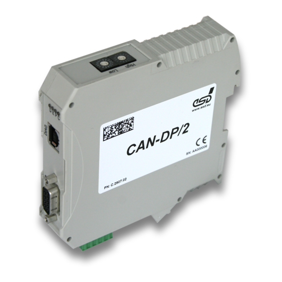
CAN-DP/2
®
CAN to PROFIBUS-DP
Slave Gateway
CANopen-DP/2
®
CANopen
to PROFIBUS-DP Slave
Gateway
Hardware Manual
to Product C.2907.02 and C.2909.02
CAN-DP/2, CANopen-DP/2
Hardware Manual • Doc. No.: C.2907.21 / Rev. 1.1
Page 1 of 34
esd electronic system design gmbh
Vahrenwalder Str. 207 • 30165 Hannover • Germany
http://www.esd.eu
Phone: +49 (0) 511 3 72 98-0 • Fax: +49 (0) 511 3 72 98-68
Advertisement
Table of Contents

Related Manuals for ESD CAN-DP/2


Summary of Contents for ESD CAN-DP/2
- Page 1 CAN-DP/2, CANopen-DP/2 Hardware Manual • Doc. No.: C.2907.21 / Rev. 1.1 Page 1 of 34 esd electronic system design gmbh Vahrenwalder Str. 207 • 30165 Hannover • Germany http://www.esd.eu Phone: +49 (0) 511 3 72 98-0 • Fax: +49 (0) 511 3 72 98-68...
- Page 2 The information in this document has been carefully checked and is believed to be entirely reliable. esd makes no warranty of any kind with regard to the material in this document, and assumes no responsibility for any errors that may appear in this document. In particular descriptions and technical data specified in this document may not be constituted to be guaranteed product features in any legal sense.
- Page 3 Changes versus previous version Date Added new chapter 'Appendix InRailBus (Option)' 2013-02-14 Updated chapter 'Order Information' Technical details are subject to change without further notice. CAN-DP/2, CANopen-DP/2 Hardware Manual • Doc. No.: C.2907.21 / Rev. 1.1 Page 3 of 34...
- Page 4 ● Do not operate the CAN-DP/2, CANopen-DP/2 adjacent to heat sources and do not expose it to unnecessary thermal radiation. Ensure an ambient temperature as specified in the technical data. ● Do not use damaged or defective cables to connect the CAN-DP/2, CANopen-DP/2 and follow the CAN wiring hints in chapter: "Correctly Wiring Electrically Isolated CAN Networks".
-
Page 5: Table Of Contents
Connecting Power Supply and CAN Signals to CBX-InRailBus........30 9.2.3 Connection of the Power Supply Voltage..............31 9.2.4 Connection of CAN......................32 Remove the CAN-CBX Module from InRailBus..............32 Declaration of Conformity......................33 CAN-DP/2, CANopen-DP/2 Hardware Manual • Doc. No.: C.2907.21 / Rev. 1.1 Page 5 of 34... - Page 6 Order Information........................34 Page 6 of 34 Hardware Manual • Doc. No.: C.2907.21 / Rev. 1.1 CAN-DP/2, CANopen-DP/2...
-
Page 7: Overview
Electrical Isolation Fig. 1: Block-circuit diagram of the CAN-DP/2 module By means of the CAN-DP/2 and CANopen-DP/2 modules, any PROFIBUS DP master can be connected to a CAN network. The CAN-DP/2 module (order no.: C.2907.02) is equipped with a VPC3+ DP-Slave controller and acts like a slave I/O component on the DP-bus, with a total of up to 300 bytes input and output data. -
Page 8: Connectors And Basic Wiring
Connectors and Basic Wiring 2. Connectors and Basic Wiring Fig. 2: Connections in operable state CAN-DP/2, CANopen-DP/2 Hardware Manual • Doc. No.: C.2907.21 / Rev. 1.1 Page 9 of 34... -
Page 9: Hardware Installation
Mount the CAN-DP/2, CANopen-DP/2 module and connect the interfaces (CAN, PROFIBUS-DP, power supply voltage). Please note that the CAN bus has to be terminated at both ends! esd offers special T- connectors and termination connectors. Additionally the CAN_GND signal has to be connected to earth at exactly one point in the CAN network. -
Page 10: Leds And Coding Switches
PROFIBUS-DP status Refer to the chapter 'Diagnosis via LED green Power LED Display' of the respective software manual for further information. green CAN bus status CAN-DP/2, CANopen-DP/2 Hardware Manual • Doc. No.: C.2907.21 / Rev. 1.1 Page 11 of 34... -
Page 11: Setting Profibus-Dp Address Via Coding Switches
The coding switch HIGH configures the more significant bits, the coding switch LOW configures the low significant bits (refer to figure above). The CAN identifier of the CAN-DP/2 can be configured via the PROFIBUS-DP configuration tool (e.g. SIMATIC Manager). Please, refer to the ‘CAN-DP/2 Software Manual’ and ‘CANopen-DP/2 Software Manual’... -
Page 12: Technical Data
Electrical isolation via magnetic couplers and DC/DC converters Bus termination terminating resistor has to be set externally, if required Connector 5-pin MINI COMBICON with spring-cage connection CAN-DP/2, CANopen-DP/2 Hardware Manual • Doc. No.: C.2907.21 / Rev. 1.1 Page 13 of 34... -
Page 13: Profibus-Dp Interface
9-pin DSUB female 5.5 Service Interface (DIAG) Type USB, for manufacturing purposes only USB specification USB 2.0 Full Speed (12 Mbit/s) Connector DIAG, USB-connector type-B Page 14 of 34 Hardware Manual • Doc. No.: C.2907.21 / Rev. 1.1 CAN-DP/2, CANopen-DP/2... -
Page 14: Connector Assignments
-... not connected Recommendation of an adapter cable from 5-pin Combicon (here line connector FK- MCP1,5/5-STF-3,81 with spring-cage-connection) to 9-pin DSUB: CAN-DP/2, CANopen-DP/2 Hardware Manual • Doc. No.: C.2907.21 / Rev. 1.1 Page 15 of 34... -
Page 15: Profibus-Dp Interface (9-Pin Dsub)
(‘Request To Send’) P5V... voltage supply for external terminating resistor networks (+5V, max. 50 mA) DGND... reference potential -... not connected Page 16 of 34 Hardware Manual • Doc. No.: C.2907.21 / Rev. 1.1 CAN-DP/2, CANopen-DP/2... -
Page 16: Power Supply Voltage
For conductor connection and conductor cross section see page 18. Pin-Position: Pin-Assignment: Signal +24 V Signal Description: +24 V... Supply voltage GND ... Reference potential - ... not connected CAN-DP/2, CANopen-DP/2 Hardware Manual • Doc. No.: C.2907.21 / Rev. 1.1 Page 17 of 34... -
Page 17: Conductor Connection/Conductor Cross Sections
2 conductors with same cross section, stranded, 1,5 mm² not allowed TWIN ferrules with plastic sleeve, max. Minimum AWG according to UL/cUL Maximum AWG according to UL/cUL Page 18 of 34 Hardware Manual • Doc. No.: C.2907.21 / Rev. 1.1 CAN-DP/2, CANopen-DP/2... -
Page 18: Correctly Wiring Electrically Isolated Can Networks
7.1.1 General Rules Note: esd grants the EC Conformity of the product, if the CAN wiring is carried out with at least single shielded single twisted pair cables that match the requirements of ISO 118982-2. Single shielded double twisted pair cable wiring as described in chapter 7.2. -
Page 19: Cabling
Use external termination plugs, because they can be rediscovered more easily than internal ● terminations within the CAN devices! 9-pin DSUB-termination connectors with male and female contacts and earth terminal are ● available as accessories Page 20 of 34 Hardware Manual • Doc. No.: C.2907.21 / Rev. 1.1 CAN-DP/2, CANopen-DP/2... -
Page 20: Heavy Industrial Environment (Double Twisted Pair Cable)
CAN_L CAN_GND wire shield n.c. n.c. connector case connector case Shield n.c. = not connected earth (FE) Figure. 7: CAN wiring for heavy industrial environment CAN-DP/2, CANopen-DP/2 Hardware Manual • Doc. No.: C.2907.21 / Rev. 1.1 Page 21 of 34... -
Page 21: Device Cabling
DSUB9 connector from ERNI (ERBIC CAN BUS MAX, order no.:154039). The usage of esd’s T-connector type C.1311.03 is not recommended for single shielded double twisted pair cables because the shield potential of the conductive DSUB housing is not looped through this T-connector type. -
Page 22: Electrical Grounding
Earthing can e.g. be made at a connector/T-connector. ● 7.4 Bus Length Optical couplers are delaying the CAN signals. esd modules typically reach a wire length of ● 37 m at 1 Mbit/s within a closed net without impedance disturbances like e.g. cable stubs >>... -
Page 23: Examples For Can Cables
74535 Mainhardt BUS-Schleppflex-PUR-C (2x 2x 0.25 mm²) Order No.: 94 025 026 (UL appr.) Germany www.concab.de Note: Configured CAN cables can be ordered from esd. Page 24 of 34 Hardware Manual • Doc. No.: C.2907.21 / Rev. 1.1 CAN-DP/2, CANopen-DP/2... -
Page 24: Can Troubleshooting Guide
- there are no open circuits in CAN_H or CAN_L wiring - your bus system has two terminating resistors (one at each end) and that they are 120 Ω each. CAN-DP/2, CANopen-DP/2 Hardware Manual • Doc. No.: C.2907.21 / Rev. 1.1 Page 25 of 34... -
Page 25: Electrical Grounding
Stop all network communication. Measure the DC voltage between CAN_H and GND (see figure above). Measure the DC voltage between CAN_L and GND (see figure above). Page 26 of 34 Hardware Manual • Doc. No.: C.2907.21 / Rev. 1.1 CAN-DP/2, CANopen-DP/2... -
Page 26: Can Transceiver Resistance Test
(>> 200%). CAN node CAN_H CAN_L transceiver CAN_GND disconnect Power CAN! disconnect power! Figure. 11: Measuring the internal resistance of CAN transceivers CAN-DP/2, CANopen-DP/2 Hardware Manual • Doc. No.: C.2907.21 / Rev. 1.1 Page 27 of 34... -
Page 27: Appendix Inrailbus (Option)
CAN_GND ... reference potential of the local CAN-Physical layers P24... power supply voltage +24 V ±10 % M24... reference potential FE... functional earth contact (EMC) (connected to mounting rail potential) Page 28 of 34 Hardware Manual • Doc. No.: C.2907.21 / Rev. 1.1 CAN-DP/2, CANopen-DP/2... -
Page 28: Using Inrailbus
9.2 Using InRailBus Note: This chapter describes the installation of the module using InRailBus for CAN-CBX- modules. For the CAN-DP/2 and CANopen-DP/2 modules the following points apply accordingly. 9.2.1 Installation of the Module Using InRailBus Connector If the CAN bus signals and the power supply voltage shall be fed via the InRailBus, please proceed as follows: Figure. -
Page 29: Connecting Power Supply And Can Signals To Cbx-Inrailbus
Plug the terminal plug into the socket on the right of the mounting-rail bus connector of the InRailBus, as described in Figure 15. Then connect the CAN interface and the power supply voltage via the terminal plug. Page 30 of 34 Hardware Manual • Doc. No.: C.2907.21 / Rev. 1.1 CAN-DP/2, CANopen-DP/2... -
Page 30: Connection Of The Power Supply Voltage
Functional earth is a current path of low impedance between current circuits and earth, which is used to increase the interference immunity. It is not intended as protective measure and does not protect against accidental contact. CAN-DP/2, CANopen-DP/2 Hardware Manual • Doc. No.: C.2907.21 / Rev. 1.1 Page 31 of 34... -
Page 31: Connection Of Can
Note: It is possible to remove individual devices from the whole without interrupting the InRailBus connection, because the contact chain will not be interrupted. Page 32 of 34 Hardware Manual • Doc. No.: C.2907.21 / Rev. 1.1 CAN-DP/2, CANopen-DP/2... -
Page 32: Declaration Of Conformity
Declaration of Conformity 10. Declaration of Conformity CAN-DP/2, CANopen-DP/2 Hardware Manual • Doc. No.: C.2907.21 / Rev. 1.1 Page 33 of 34... - Page 33 Table 2: Order information PDF Manuals Manuals are available in English and usually in German as well. Available manuals are listed in the following table. Please download the manuals as PDF documents from our esd website www.esd.eu for free. Manuals Order No. CAN-DP/2-MD CAN-DP/2 manual in German C.2907.20...
Need help?
Do you have a question about the CAN-DP/2 and is the answer not in the manual?
Questions and answers