Audio Technica ATND1061DAN User Manual
Beamforming array microphone
Hide thumbs
Also See for ATND1061DAN:
- User manual (107 pages) ,
- Operation manual (17 pages) ,
- Manual (9 pages)

Related Manuals for Audio Technica ATND1061DAN


Summary of Contents for Audio Technica ATND1061DAN
- Page 1 ATND1061DAN Beamforming Array Microphone User Manual - Main Unit Edition - English...
-
Page 2: Table Of Contents
Flush mounting Connection procedure System connection examples ATND1061DAN (single cable mode) ATND1061DAN (split mode) ATND1061DAN (connecting multiple units) ATND1061DAN (single cable mode and analog I/O) Connecting Euroblock connectors GPI port Reset button Checking the network mode Network reset Factory reset... - Page 3 Table of Contents Dante Controller Dante channel list Input (Dante Transmitter) Output (Dante Receiver) Web Remote What is Web Remote? What is Locate? Recommended environment OS for running Web Remote and Locate Recommended web browsers for Web Remote Preparation for Web Remote Connecting the microphone with the control device Setting up Locate Launching Web Remote...
- Page 4 Displaying descriptions of errors Presets Saving presets Recalling presets Function List Troubleshooting Dimensions ATND1061DAN Surface mount adapter Flush mount adapter Flush mount cover Tile bridge A Tile bridge B Tile bridge C Assembly diagram of tile bridge for grid ceiling...
-
Page 5: Safety Precautions
Safety precautions Although this product was designed to be used safely, failing to use it correctly may result in an accident. To ensure safety, observe all warnings and cautions while using the product. The product is intended for commercial use, not for general use. Disconnect the product from a device if the product begins to malfunction, producing smoke, odor, heat, unwanted noise or showing other signs of damage. -
Page 6: For Customers In Canada
Safety precautions Caution You are cautioned that any changes or modifications not expressly approved in this manual could void your authority to operate this equipment. Note This equipment has been tested and found to comply with the limits for a Class B digital device, pursuant to part 15 of the FCC Rules. -
Page 7: Installation Precautions
Installation precautions This product should be installed by a professional contractor. When determining the installation location and method, be sure to consider the applicable laws and ordinances for the area where the product is being installed. Audio-Technica assumes no responsibility in the event of accidents such as the product dropping due to insufficient strength of the installation site or improper installation. -
Page 8: Maintenance
Maintenance When dirty or dusty, wipe clean using a dry, soft cloth. Do not use benzine, paint thinners, or electrical contact cleaners. Doing so may cause deformation or malfunction. -
Page 9: Package Contents
Package contents Microphone IR remote controller Includes a lithium coin battery. - Page 10 Package contents Surface mount adapter Screw (M4 × 50 mm) × 4 Flush mount adapter Flush mount cover Screw (M4 × 10 mm) × 12 Hole cover Nut × 4 Snap bushing × 2 Tile bridge A × 2 Tile bridge B × 2 Tile bridge C ×...
-
Page 11: Part Names And Functions
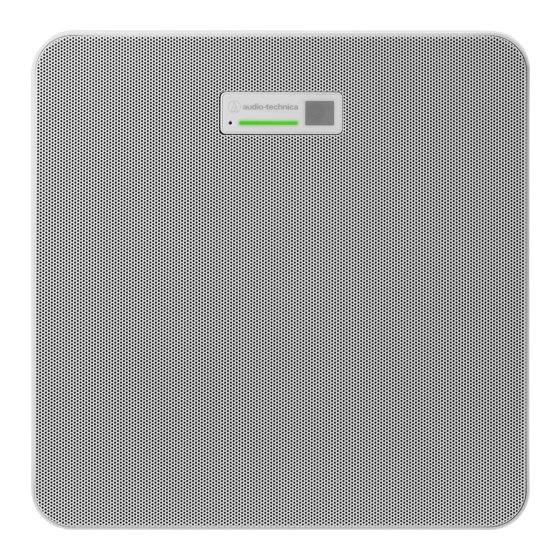
Part names and functions Microphone ATND1061DAN Reset button Insert the tip of a pin or other thin device and press this button to reset the microphone. Indicator lamp IR receiver Release button Hole for zip tie Screw holes for VESA mount Used when installing with a VESA mount. -
Page 12: Indicator Lamp
Part names and functions GPI port For details, see "GPI port" (p. 47). 1: GPI1 2: GPI2 G: Ground Screw for grounding Perform grounding as necessary. Screw for seismic cable Indicator lamp The colors of the indicator lamp can be used to confirm the microphone status. Indicator lamp Status Lights in green... -
Page 13: How To Change Presets
Part names and functions Power save mode / cancel button Used to turn the power save mode on/off and for canceling preset settings. Mute/confirm button Used to turn All Mute on/off and for finalizing preset settings. Preset mode button Used to change preset settings. Battery cover Includes a lithium coin battery (for confirming initial operation). -
Page 14: Installation
Installation Hard ceiling installation Surface mounting Completed installation Parts required for installation Surface mount adapter Screw (M4 × 50 mm) × 4 Tile bridge A × 2 Tile bridge B × 2 Seismic cable Zip tie Installation template... - Page 15 Installation Drill holes in the ceiling for attaching the microphone. Use the enclosed installation template to drill mounting holes according to the specified dimensions. Installation may not be possible in some areas depending on the placement of the ceiling frame. Check the internal structure of the ceiling before choosing an installation location.
- Page 16 Installation Stamping indicating microphone orientation Run the cables inside the ceiling. Attach the seismic cable to the ceiling frame. Securely attach the seismic cable to a strong point on the ceiling frame. Slide the unlock pins to release the lock for adjusting the wire. Unlock pins...
- Page 17 Installation Attach the seismic cable so that there is as little slack as possible. Using the seismic cable with a large amount of slack could increase the impact exerted were the microphone to be dropped and may result in an accident, injury, or damage to the microphone. If the impact from a fall is applied to the seismic cable, replace the cable with a new one.
- Page 18 Installation Zip tie Tab on surface mount adapter Tighten the zip tie to secure.
-
Page 19: Flush Mounting
Installation Flush mounting Completed installation Parts required for installation Surface mount adapter... - Page 20 Installation Flush mount adapter Flush mount cover Screw (M4 × 10 mm) × 12 Hole cover Nut × 4 Snap bushing × 2 Tile bridge A × 2 Tile bridge B × 2 Tile bridge C × 4 Seismic cable Safety belt Installation template Cut out a square hole in the ceiling for attaching the microphone.
- Page 21 Installation Attach the surface mount adapter to the flush mount adapter using the screws (M4 × 10 mm). Align the arrows on both the flush mount adapter and the stamping on surface mount adapter when attaching. Attach the hole cover with the nuts. If using both holes, skip this step and proceed to the next step.
- Page 22 Installation Attach the snap bushings. Press your hand on the snap bushing from above to insert it into the wiring hole. When wiring a large number of cables, attach both snap bushings without using the hole cover. Run the cables inside the ceiling. Attach the seismic cable to the ceiling frame.
- Page 23 Installation Unlock pins Attach the seismic cable so that there is as little slack as possible. Using the seismic cable with a large amount of slack could increase the impact exerted were the microphone to be dropped and may result in an accident, injury, or damage to the microphone. If the impact from a fall is applied to the seismic cable, replace the cable with a new one.
- Page 24 Installation Connect the wired cables to the microphone. See "Connection procedure" (p. 42) for details on connecting the cables. Attach the microphone to the surface mount adapter. Make sure the tab on the surface mount adapter is securely hooked on the microphone before pushing up the other side of the microphone to attach it.
-
Page 25: Grid Ceiling Installation
Installation Attach the flush mount cover by inserting it into the flush mount adapter. Avoid bending or twisting the safety belt when attaching the flush mount cover. Grid ceiling installation Surface mounting Completed installation... - Page 26 Installation Parts required for installation Surface mount adapter Screw (M4 × 50 mm) × 4 Tile bridge A × 2 Tile bridge C × 4 Screw (M4 × 10 mm) × 4 Seismic cable Zip tie Installation template Remove the ceiling tile where the microphone will be installed. Drill holes in the ceiling tile for attaching the microphone.
- Page 27 Installation 106 mm 106 mm φ 4- 5 mm Attach tile bridges A behind the ceiling tile. Attach tile bridges C loosely to tile bridges A using the screws (M4 × 10 mm). Align the screw holes of tile bridges A with the holes drilled into the ceiling tile to attach. Attach the surface mount adapter using the screws (M4 ×...
- Page 28 Installation Stamping indicating microphone orientation Run the cables inside the ceiling. Attach the seismic cable to the ceiling frame. Securely attach the seismic cable to a strong point on the ceiling frame. Slide the unlock pins to release the lock for adjusting the wire. Unlock pins Attach the seismic cable so that there is as little slack as possible.
- Page 29 Installation Adjust the tile bridge C assembly to the height of the ceiling frame and tighten the screws (M4 × 10 mm) to attach. Securely attach tile bridges A and C to the ceiling frame so that a sufficient load can be supported. If the placement of the ceiling frame makes it difficult to ensure a secure installation, use nuts and bolts to attach tile bridges A securely to the ceiling frame mounting holes.
- Page 30 Installation Screw for seismic cable Connect the wired cables to the microphone. See "Connection procedure" (p. 42) for details on connecting the cables. Pass the zip tie through the microphone and the surface mount adapter to attach the microphone to the surface mount adapter.
-
Page 31: Flush Mounting
Installation Flush mounting Completed installation... - Page 32 Installation Parts required for installation Surface mount adapter Flush mount adapter Flush mount cover Screw (M4 × 10 mm) × 12 Hole cover Nut × 4 Snap bushing × 2 Tile bridge A × 2 Tile bridge B × 2 Tile bridge C ×...
- Page 33 Installation Installation template Remove the ceiling tile where the microphone will be installed. Cut out a square hole in the ceiling for attaching the microphone. Use the enclosed installation template to cut out a mounting hole according to the specified dimensions. Align the mounting holes with the center of the ceiling tile.
- Page 34 Installation Attach the surface mount adapter to the flush mount adapter using the screws (M4 × 10 mm). Align the arrows on both the flush mount adapter and the stamping on surface mount adapter when attaching. Attach the hole cover with the nuts. If using both holes, skip this step and proceed to the next step.
- Page 35 Installation Attach the snap bushings. Press your hand on the snap bushing from above to insert it into the wiring hole. When wiring a large number of cables, attach both snap bushings without using the hole cover. Insert the flush mount adapter into the square hole cut into the ceiling tile, and secure with screws to attach the flush mount adapter.
- Page 36 Installation Attach the seismic cable to the ceiling frame. Securely attach the seismic cable to a strong point on the ceiling frame. Slide the unlock pins to release the lock for adjusting the wire. Unlock pins Attach the seismic cable so that there is as little slack as possible. Using the seismic cable with a large amount of slack could increase the impact exerted were the microphone to be dropped and may result in an accident, injury, or damage to the microphone.
- Page 37 Installation Adjust the tile bridge C assembly to the height of the ceiling frame and tighten the screws (M4 × 10 mm) to attach. Securely attach tile bridges A, B, and C to the ceiling frame so that a sufficient load can be supported. If the placement of the ceiling frame makes it difficult to ensure a secure installation, use nuts and bolts to attach tile bridges A securely to the ceiling frame mounting holes.
- Page 38 Installation Screw for seismic cable Connect the wired cables to the microphone. See "Connection procedure" (p. 42) for details on connecting the cables. Attach the microphone to the surface mount adapter. Make sure the tab on the surface mount adapter is securely hooked on the microphone before pushing up the other side of the microphone to attach it.
-
Page 39: Installation With Vesa Mount
Installation Hooks for safety belt attachment Attach the flush mount cover by inserting it into the flush mount adapter. Avoid bending or twisting the safety belt when attaching the flush mount cover. Installation with VESA mount Installation is possible using a commercially available VESA mount. VESA standard dimensions: 75 mm pitch Mounting screw hole: M4 (8 mm depth) Do not use screws with a length that exceeds the sum of the mounting screw hole depth (8 mm) of this product and... -
Page 40: Removing The Microphone
Installation To prevent the product from falling, secure the seismic cable to the microphone before attaching it to a strong location on the structure of the VESA mount. 75 mm 75 mm Screw holes for VESA mount Screw for seismic cable Removing the microphone Surface mounting Cut away the zip tie used to secure the microphone to the surface mount adapter. -
Page 41: Flush Mounting
Installation Flush mounting Insert a flathead screwdriver between the recesses located on the sides of the flush mount cover (two on each side) and the flush mount adapter. Then lower and remove the flush mount cover. The tabs on the flush mount cover hook onto the flush mount adapter. Insert a flathead screwdriver as far into the recess of the flush mount cover as possible and lower the flush mount cover downward while pushing in the tab. - Page 42 Installation...
-
Page 43: Connection Procedure
Connection procedure System connection examples ATND1061DAN (single cable mode) ATND1061DAN ATND1061DAN Back Speaker Power amplifier PoE switching hub Dante DSP Far-end source Internet Router Computer Video conference system... -
Page 44: Atnd1061Dan (Split Mode)
Connection procedure ATND1061DAN (split mode) ATND1061DAN ATND1061DAN Back Speaker IP Control Dante audio PoE switching hub Power amplifier Switching hub Far-end source Dante DSP Internet Router Computer Video conference system... -
Page 45: Atnd1061Dan (Connecting Multiple Units)
Connection procedure ATND1061DAN (connecting multiple units) ATND1061DAN ATND1061DAN ATND1061DAN ATND1061DAN ATND1061DAN Back Speaker Power amplifier PoE switching hub Dante DSP Far-end source Internet Router Computer Video conference system For details on auto mix settings when connecting multiple units, see the user manual -Digital Microphone... -
Page 46: Atnd1061Dan (Single Cable Mode And Analog I/O)
Connection procedure ATND1061DAN (single cable mode and analog I/O) ATND1061DAN OUTPUT INPUT ATND1061DAN Back IP Control Speaker PoE switching hub Power amplifier Far-end source Internet Router Computer Video conference system OUTPUT: Connection to analog input for video conference system (far-end transmission) - Page 47 Connection procedure Approx. 5 mm Approx. 20 mm Loosen the screws with a flathead screwdriver. Check the pin assignments and connect each cable. Terminal Pin assignments A (+: Hot) INPUT B (−: Cold) C (G: Ground) A (+: Hot) OUTPUT B (−: Cold) C (G: Ground) A (1: GPI1)
-
Page 48: Gpi Port
Connection procedure Connect the Euroblock connector to the microphone. GPI port The function of the GPI port can be selected under “GPI Setting” in Digital Microphone Manager. The function assigned to the GPI port is executed by closing the GPI port and ground port. Close them for at least 0.5 seconds. -
Page 49: Reset Button
Reset button Insert the tip of a pin or other thin device and press the reset button to reset the microphone. Resetting can be performed only during normal operating mode. Pressing the reset button while in power save mode will return to normal operating mode. Indicator lamp Reset button Checking the network mode... -
Page 50: Factory Reset
Reset button Factory reset Performing a factory reset will result in all settings being reset to factory default. Press and hold the reset button for approximately 8 seconds. The indicator lamp will switch between being lit in green and orange. Press the reset button while the indicator lamp is switching between being lit in green and orange. -
Page 51: Digital Microphone Manager
Digital Microphone Manager Digital Microphone Manager is a software application that supports the operation of digital microphones (supported models) from Audio-Technica. It enables users to create projects, configure microphone and audio settings, as well as set a microphone coverage range that suits the layout of rooms where microphones are actually installed. It also enables users to perform real-time editing and display speaker positions in an online environment, a useful feature for on-site adjustments of advanced settings. -
Page 52: Dante Controller
Dante Controller ATND1061DAN is compatible with Dante network audio. I/O settings for Dante devices can be set using Dante Controller (application provided by Audinate). For information on Dante Controller, visit the Audinate website (www.audinate.com). Dante channel list Input (Dante Transmitter) -
Page 53: Web Remote
Web Remote What is Web Remote? Web Remote is a web application used to control microphones. Web Remote enables the following remote control tasks to be performed from your Windows PC, Mac, iOS or Android device (hereinafter “control device”). Checking microphone status Changing microphone settings What is Locate? Locate is a launcher application for Web Remote. -
Page 54: Preparation For Web Remote
Web Remote Preparation for Web Remote Connecting the microphone with the control device Connect the control device with the microphone via a wired or wireless connection. Perform network settings for the control device and connect to the network. The microphone ships from the factory with “IP Config Mode” set to “Auto”. To connect using a static IP address, set “IP Config Mode”... -
Page 55: Launching Web Remote
Web Remote Launching Web Remote Launch from Locate Launch Locate installed to the control device. From the list, select the microphone for which Web Remote will be launched. Once Web Remote is launched, the Setting & Maintenance screen will appear. Launch by directly specifying the IP address If you know the IP address of the microphone, Web Remote can be launched by directly specifying the IP address. - Page 56 Web Remote For settings requiring text input, click the field for the setting to input text. For settings requiring selection from a pull-down menu, click “ ” in the field for the setting and make a selection from the pull-down menu. For settings requiring use of a switch, click the switch.
-
Page 57: General (System Settings)
Web Remote General (System Settings) Device Name Item Description Device Name Set the microphone name. Device ID Set the microphone ID. Device Color Set display colors for microphones on Digital Microphone Manager. LED Settings Item Description Unmute Color Set indicator lamp colors for microphones when unmuted. Mute Color Set indicator lamp colors for microphones when muted. -
Page 58: Dante & Audio Port Settings
Web Remote Dante & Audio Port Settings Item Description Set the configuration mode for the IP address. When “Auto” is selected, IP addresses are automatically assigned by IP Config Mode DHCP servers, etc. When “Static” is selected, static IP addresses are used. IP Address Set the IP address. -
Page 59: Ip Control Settings
Web Remote IP Control Settings Item Description Port Number Shows the IP control port number. Set whether to receive notifications from microphones during IP control. Notification Notifications will be received when set to “ON” (blue). Set whether to receive audio level notifications from microphones during Audio Level Notification IP control. -
Page 60: Reset All Settings To Default
Web Remote Click “Update”. The update will start. Once the update is complete, a completion screen will appear and the microphone will automatically reboot. Reset All Settings to Default All microphone settings will be reset to factory default. However, the firmware version will remain the same. Click “Reset”. -
Page 61: Audio (Install Settings)
Web Remote Audio (Install Settings) Beam CHs Configure audio settings for CH1 to CH6. Item Description Input Gain Set the input gain of the audio input. Set whether to cut the low-pass range of the input audio. Low Cut Setting to “ON” (blue) will cut the low-pass range of the input audio. Set whether to apply 4-band EQ to the audio input. -
Page 62: Auto Mix Ch
Web Remote Auto Mix CH Item Description Set whether to enable the acoustic echo canceler. Setting to “ON” (blue) will enable this function. Set the reference signal. Normally, audio from a microphone at another AEC Reference site would be selected. Set whether to enable noise cancellation. -
Page 63: Exporting Presets
Web Remote Exporting presets Export presets to a file. Click the button(s) of the preset(s) to be exported to a file. Click “Export”. Export after specifying the export location and file name. Importing presets Import exported preset files. Click the button(s) of the import destination preset(s). - Page 64 Web Remote Click “Browse”. Select and open preset files from the file selection screen. Click “Import”. The preset(s) will be imported.
-
Page 65: Logging
Web Remote Logging Perform settings for log messages and download log files. Item Description Set whether to save log messages. Enabled Setting to “ON” (blue) will save log messages. Set whether to write log messages to internal memory or forward them to Destination a Syslog server. -
Page 66: Displaying Descriptions Of Errors
Web Remote Microphone color This mark is displayed when operating multiple microphones. Microphone name The name set for the device is displayed. IP remote status Indicates that control is being performed via IP. : Not under remote control. : Under remote control. : There is a remote control error. -
Page 67: Saving Presets
Web Remote Saving presets Click “Preset”. “Preset” shows the name of the current preset. Click “Save Preset” in the pull-down menu. Click the slot where the preset is to be saved. Enter a name. Click “Save”. It may take several minutes to save presets. Settings for the microphone are saved in the preset. - Page 68 Web Remote Click “Recall Preset” in the pull-down menu. Click the preset to be recalled. The preset is reflected in the microphone settings.
-
Page 69: Function List
Function List Default Presets Item Setting values Resumed Setting Included Remote (Maximum 30 characters Device Name Device Name ATND1061 (ASCII code only)) Device ID 0 to 255 Green, Yellow, Red, Pink, Blue, Device Color Green Cyan Command Link Preset Link On, Off Mute Link On, Off... - Page 70 Function List Default Presets Item Setting values Resumed Setting Included Remote Audio Level On, Off Notification Camera Control On, Off Notification Multicast 0.0.0.0 to 255.255.255.255 239.0.0.100 Address Multicast 00001 to 65535 17000 Port Number Beam Beam Settings Low, Mid, High Sensitivity Auto On, Off...
- Page 71 Function List Default Presets Item Setting values Resumed Setting Included Remote Y: 16.4 feet/5000 mm 3.3 feet/1,000 mm to room Altitude Room height height Beam CH 1 Channel Settings CH # Coverage, Priority1~5 to 6 Input Gain 0 dB to +30 dB 0 dB Lowcut On, Off...
- Page 72 Function List Default Presets Item Setting values Resumed Setting Included Remote CH Mute On, Off Auto Mix Enabled On, Off Weight -15.0 to 15.0 Gain Share Mode Stand Alone, Link Stand Alone Mode 4 Band EQ Easy Mode, Expert Mode Expert Mode Change Easy Mode...
- Page 73 Function List Default Presets Item Setting values Resumed Setting Included Remote Band#4 Q 0.3 to 60 0.75 value Band#4 LPF, HSH, PEQ Filter type On, Off Analog Input, Digital Input Analog Input Reference On, Off Low, Mid, High Sensitivity On, Off Attenuation 0 to 20 Level...
-
Page 74: Troubleshooting
Troubleshooting Please check the following when problems with the microphone occur. Also see the user manual -Digital Microphone Manager Edition-. Check whether the microphone is connected correctly. Check whether the microphone is operating as described in the user manual. Check whether external devices are operating correctly. Perform this check with the microphone disconnected. Restart network devices. - Page 75 Troubleshooting No sound emitted from analog output Check whether the analog I/O ports on the back of the microphone are connected correctly. Check whether the pin assignments for the analog I/O ports on the back of the microphone are correct. Strange noises are emitted Check whether the target zone is set to the effective range in the beam settings of Digital Microphone Manager.
- Page 76 Troubleshooting No incoming IP control notifications Check Digital Microphone Manager and Web Remote to see whether “IP Control Settings” > “Notification” is set to “ON”.
-
Page 77: Dimensions
Dimensions ATND1061DAN 227.5 (Unit: mm) -
Page 78: Surface Mount Adapter
Dimensions Surface mount adapter 204.5 44.5 2×4.4 45.8 (Unit: mm) -
Page 79: Flush Mount Adapter
Dimensions Flush mount adapter (Unit: mm) -
Page 80: Flush Mount Cover
Dimensions Flush mount cover (Unit: mm) Tile bridge A 10.5 (Unit: mm) -
Page 81: Tile Bridge B
Dimensions Tile bridge B 372.4 (Unit: mm) Tile bridge C (Unit: mm) -
Page 82: Assembly Diagram Of Tile Bridge For Grid Ceiling
Dimensions Assembly diagram of tile bridge for grid ceiling 10.5 34.5 17.5 6×9 5×20 5×20 6×9 17.5 34.5 Center Adjust Max84.5 Center Adjust Max84.5 635.6 (Unit: mm) -
Page 83: Specifications
Specifications ATND1061DAN General Power requirement PoE (IEEE 802.3af Class 0) Max. 7 W Power consumption Operation temperature range 0°C to 40°C (32°F to 104°F) Operation humidity range 25% to 85% (Noncondensing) Dimensions 227.5 mm (9.0”) × 227.5 mm (9.0”) × 30 mm (1.2”) (W × D × H) -
Page 84: Other
Specifications Other Dante: 1 Gbps Network IP control: 100 Mbps Sampling rate: 48 kHz Digital audio Bit depth: 24 bit Microphone (CH1 to CH6): 47 msec Latency Microphone (Auto Mix CH): 79 msec Dante: Min. 250 usec, Max. 5 msec Network/Dante: RJ-45 Analog input: Euroblock 3pin I/O connector... -
Page 85: Polar Pattern / Frequency Response
Polar pattern / Frequency response Polar pattern 0˚ 330˚ 30˚ 300˚ 60˚ 270˚ 90˚ 120˚ 240˚ 150˚ 210˚ 180˚ LEGEND 200 Hz SCALE IS 1 kHz 5 DECIBELS PER DIVISION 5 kHz 8 kHz Frequency response 60 - 18,000 Hz 10 dB Frequency in Hertz LEGEND... -
Page 86: Trademarks
Trademarks ® ® Microsoft and Windows are registered trademarks of Microsoft Corporation in the United States and/or other countries. Microsoft Windows operating system is indicated in its abbreviated form as Windows. Mac OS and Safari are trademarks of Apple Inc., registered in the U.S. and other countries. Android and Google Chrome are trademarks of Google LLC. -
Page 87: System Diagram
Audio-Technica Beamforming Array Microphone ATND1061DAN Signal Diagram Audio data Control data Gain Share Gain Share Control BUS Auto ATT ON/OFF Voice Activity Auto Mix Elevation Angle Detection Input Meter 4Band Level Mute Beam#1 Auto Tx1:CH 1 Gain Gain Share MicGain Fader 0dB ~... - Page 88 株式会社オーディオテクニカ 〒194-8666 東京都町田市西成瀬2-46-1 www.audio-technica.co.jp Audio-Technica Corporation 2-46-1 Nishi-naruse, Machida, Tokyo 194-8666, Japan www.audio-technica.com ©2022 Audio-Technica Corporation Global Support Contact: www.at-globalsupport.com 142700180-02-01 ver.1 2022.02.01...
Need help?
Do you have a question about the ATND1061DAN and is the answer not in the manual?
Questions and answers