
Related Manuals for Weishaupt WG20 1-C Z-LN Series


Summary of Contents for Weishaupt WG20 1-C Z-LN Series
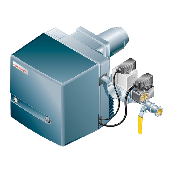
- Page 1 Installation and operating instruction Gas burner WG20…/1-C Z-LN 83054602 1/2020-01...
-
Page 2: Table Of Contents
Installation and operating instruction Gas burner WG20…/1-C Z-LN User instructions ...................... 5 1.1 Target group ........................ 5 1.2 Symbols .......................... 5 1.3 Guarantee and Liability .................... 6 Safety ............................. 7 2.1 Designated application .................... 7 2.2 When gas can be smelled .................. 7 2.3 ... - Page 3 Installation and operating instruction Gas burner WG20…/1-C Z-LN Commissioning ...................... 31 7.1 Prerequisite ......................... 31 7.1.1 Connect measuring devices ................ 32 7.1.2 Check gas connection pressure .............. 33 7.1.3 Check soundness of gas valve train .............. 34 7.1.4 Purging the gas valve train ................ 37 7.1.5 ...
- Page 4 Installation and operating instruction Gas burner WG20…/1-C Z-LN Project planning ...................... 81 12.1 Continuous running fan or post-purge ............... 81 Spares .......................... 82 Notes ........................... 92 Key word index ...................... 93 4-96 83054602 1/2020-01 La...
-
Page 5: User Instructions
Installation and operating instruction Gas burner WG20…/1-C Z-LN 1 User instructions 1 User instructions This manual forms part of the equipment and must be kept on site. Translation of original Carefully read the manual prior to working on the unit. operating instructions 1.1 Target group The manual is intended for the operator and qualified personnel. -
Page 6: Guarantee And Liability
Weishaupt parts, force majeure, unauthorised modifications made to the unit, the installation of additional components, which have not been tested with the... -
Page 7: Safety
Installation and operating instruction Gas burner WG20…/1-C Z-LN 2 Safety 2 Safety 2.1 Designated application The burner is suitable for operation on heat exchangers to EN 303 and EN 676. If the burner is not used on combustion chambers to EN 303 and EN 676, a safety assessment of combustion and flame stability during individual process conditions and of the shutdown limits of the combustion plant has to be carried out and docu- mented. -
Page 8: Electrical Work
Carry out soundness test after each service and fault rectification. 2.4 Alterations to the construction of the equipment All conversions require written approval from Max Weishaupt GmbH. No additional components may be fitted, which have not been tested for use with the equipment. -
Page 9: Product Description
Installation and operating instruction Gas burner WG20…/1-C Z-LN 3 Product description 3 Product description 3.1 Type key Example: WG20N/1-C Z-LN Type Series: Compact burner Fuel: Gas Size N: Natural Gas F: Liquid Petroleum Gas Ratings size Construction Version Type of control: two stage Mixing head: LowNO 9-96 83054602 1/2020-01 La... -
Page 10: Serial Number
Installation and operating instruction Gas burner WG20…/1-C Z-LN 3 Product description 3.2 Serial number The serial number on the name plate identifies the product. This is required by Weishaupt's customer service department. 1 Name plate Ser.No. 10-96 83054602 1/2020-01 La... -
Page 11: Function
Installation and operating instruction Gas burner WG20…/1-C Z-LN 3 Product description 3.3 Function 3.3.1 Air supply Air damper The air damper regulates the air quantity required for combustion. The combustion manager drives the air damper via actuator. At burner shutdown the the actuator automatically closes the air damper. At burner shutdown the air dampers close automatically. -
Page 12: Gas Supply
Installation and operating instruction Gas burner WG20…/1-C Z-LN 3 Product description 3.3.2 Gas supply Gas isolating valve 1 The gas isolating valve opens and shuts off the gas supply. Multifunction assembly 8 The multifunction assembly contains: Gas filter 2 The gas filter protects the subsequent valve train components from foreign particles. -
Page 13: Electrical Components
Installation and operating instruction Gas burner WG20…/1-C Z-LN 3 Product description High gas pressure switch 6 (optional) The high gas pressure switch monitors the setting pressure. If the setting pressure exceeds the value set, the combustion manager initiates a controlled shutdown. 3.3.3 Electrical components Combustion Manager The combustion manager W-FM is the control unit of the burner. -
Page 14: Program Sequence
Installation and operating instruction Gas burner WG20…/1-C Z-LN 3 Product description 3.3.4 Program sequence Pre-purge At heat demand, the actuator drives to full load position after the initialisation time ) has elapsed. The burner motor starts and the air pressure switch reacts. The combustion chamber is pre-purged. - Page 15 Installation and operating instruction Gas burner WG20…/1-C Z-LN 3 Product description W-FM 10 T1 T2 T6 T8 P6 P11 1234 Ionisation electrode Initialisation time (Test): 3 s Air pressure switch Post-purge time: 1.2 s Temperature or pressure regulator Post-purge time: 2.5 s Temperature or pressure regulator full load First test phase: 9.3 s (valve proving valve 1) Low gas pressure switch 2nd test phase: 9.7 s (valve proving valve 2)
-
Page 16: Technical Data
Temperature during transport / storage –20 … +70 °C relative humidity max 80 %, no dew point Installation elevation max 2000 m Consultation with Weishaupt is required for higher installation elevation. 3.4.4 Fuels Natural Gas E/LL Liquid Petroleum Gas B/P 16-96 83054602 1/2020-01 La... -
Page 17: Emissions
(temperature and humidity) medium temperature Combustion chamber dimensions, see Weishaupt Partner Portal / Documents and Applications / Online Applications / NO calculation for burners. Sound levels Dual number noise emission values... -
Page 18: Rating
Installation and operating instruction Gas burner WG20…/1-C Z-LN 3 Product description 3.4.6 Rating Combustion heat rating Natural Gas 35 … 200 kW Liquid Petroleum Gas 35 … 200 kW Combustion head WG20-C Capacity graph Capacity graph to EN 676. The capacity data given relates to an installation elevation of 0 m above sea level. For installation elevations above 0 m a capacity reduction of approx. 1 % per 100 m applies. -
Page 19: Dimensions
Installation and operating instruction Gas burner WG20…/1-C Z-LN 3 Product description 3.4.7 Dimensions Burner –weishaupt– 32 mm 358 mm 158 mm 397 mm 1 140 mm without combustion head extension 240 mm with combustion head extension (100 mm) 340 mm with combustion head extension (200 mm) -
Page 20: Weight
Installation and operating instruction Gas burner WG20…/1-C Z-LN 3 Product description Gas valve train Gas valve Isolating With thermal Without thermal train valve shut off device shut off device 1 W-MF 507 Rp¾ approx. 315 mm approx. 300 mm approx. 320 mm approx. -
Page 21: Installation
Installation and operating instruction Gas burner WG20…/1-C Z-LN 4 Installation 4 Installation 4.1 Installation conditions Burner type and capacity graph Burner and heat exchanger must be matched. Check burner type and burner capacity. Installation location Prior to installation ensure that: sufficient space is available for normal and service position [ch. 3.4.7], sufficient combustion air is available, if necessary install ducted air intake, Prepare heat exchanger... -
Page 22: Burner Installation
Installation and operating instruction Gas burner WG20…/1-C Z-LN 4 Installation 4.2 Burner installation Only valid in Switzerland When installing and operating the regulations of SVGW, VKF, local and Cantonal regulations and the EKAS guideline (LPG Guideline Part 2) must be observed. The burner in its standard version is designed for valve train connection from the right. -
Page 23: Rotate Burner By 180° (Optional)
Installation and operating instruction Gas burner WG20…/1-C Z-LN 4 Installation 4.2.1 Rotate burner by 180° (optional) The following are required for the conversion: actuator adapter with fixing screws, lever with a longer shaft. Remove actuator 1. Disconnect linkage 3. Remove complete lever 2. Fit lever with longer shaft 4 to angle drive. - Page 24 Installation and operating instruction Gas burner WG20…/1-C Z-LN 4 Installation Rotate burner flange 1 180° and mount with flange gasket. Rotate burner 180° and fit screws 2 to burner flange. The aperture between combustion head and refractory should be filled with flame-proof, resilient insulating material (do not make solid).
-
Page 25: Installation
Installation and operating instruction Gas burner WG20…/1-C Z-LN 5 Installation 5 Installation 5.1 Gas supply Risk of explosion due to leaking gas Gas leaks can lead to a build-up of explosive gas/air mixture. With an ignition source present this can result in an explosion. Install gas supply with care. -
Page 26: Installing The Gas Valve Train
Installation and operating instruction Gas burner WG20…/1-C Z-LN 5 Installation 5.1.1 Installing the gas valve train Only in conjunction with W-MF and gas connection pressure > 150 mbar If the gas connection pressure is > 150 mbar, a pressure regulator has to be fitted upstream of the W-MF. - Page 27 Installation and operating instruction Gas burner WG20…/1-C Z-LN 5 Installation Installing the gas valve train from the left To fit the gas valve train to the burner from the left, the burner has to be installed rotated by 180°. To do this, additional conversion measures are required. Move the gas pressure switch prior to installing the multifunction assembly: Remove closing plug 1 and gas pressure switch 3.
-
Page 28: Carry Out Soundness Test Of Gas Supply Line And Vent
Installation and operating instruction Gas burner WG20…/1-C Z-LN 5 Installation 5.1.2 Carry out soundness test of gas supply line and vent Only the gas supply company or a contract installation company may carry out a soundness test and vent the gas line. 28-96 83054602 1/2020-01 La... -
Page 29: Electrical Connection
Installation and operating instruction Gas burner WG20…/1-C Z-LN 5 Installation 5.2 Electrical connection Risk of electric shock Working on the device when voltage is applied can lead to electric shock. Isolate the device from the power supply prior to starting any work. DANGER Safeguard against accidental restart. -
Page 30: Operation
Installation and operating instruction Gas burner WG20…/1-C Z-LN 6 Operation 6 Operation 6.1 Operating panel Damage to the combustion manager due to incorrect operation Excessive pressure applied to the illuminated push button can damage the com- bustion manager. Only lightly press illuminated push button. CAUTION The illuminated push button on the combustion manager has the following func- tions:... -
Page 31: Commissioning
Installation and operating instruction Gas burner WG20…/1-C Z-LN 7 Commissioning 7 Commissioning 7.1 Prerequisite Commissioning must only be carried out by qualified personnel. Only correctly carried out commissioning ensures the operational safety. Do not operate the burner outside of the capacity graph [ch. 3.4.6]. Prior to commissioning ensure that: all assembly and installation work has been carried out correctly, sufficient combustion air is available, if necessary install ducted air intake... -
Page 32: Connect Measuring Devices
Installation and operating instruction Gas burner WG20…/1-C Z-LN 7 Commissioning 7.1.1 Connect measuring devices Measuring device for ionisation current Remove ionisation cable from the plug coupling. Connect current measuring device in series. Ionisation current Extraneous light detection from 0.8 μA Minimum ionisation current 1.5 μA Recommended ionisation current... -
Page 33: Check Gas Connection Pressure
Installation and operating instruction Gas burner WG20…/1-C Z-LN 7 Commissioning 7.1.2 Check gas connection pressure Minimum connection pressure Add the combustion chamber pressure in mbar to the minimum connection pres- sure. The connection pressure should not fall below 15 mbar. Determine minimum connection pressure for low pressure installations from table [ch. 7.1.5]. -
Page 34: Check Soundness Of Gas Valve Train
Installation and operating instruction Gas burner WG20…/1-C Z-LN 7 Commissioning 7.1.3 Check soundness of gas valve train Carry out soundness test: prior to commissioning, after all service and maintenance work. First test phase Second and third test phase Test pressure 100 mbar ±10 % 100 mbar ±10 % Waiting time for pressure equal-... - Page 35 Installation and operating instruction Gas burner WG20…/1-C Z-LN 7 Commissioning Third test phase In the third phase the valve train section from the multifunction assembly up to the gas butterfly valve is tested. Remove mixing head [ch. 9.3]. Fit blanking plate 4. Fit mixing head.
- Page 36 Installation and operating instruction Gas burner WG20…/1-C Z-LN 7 Commissioning Test points 1 Pressure into valve 1 2 Pressure between valve 1 and valve 2 3 Pressure after valve 2 36-96 83054602 1/2020-01 La...
-
Page 37: Purging The Gas Valve Train
Installation and operating instruction Gas burner WG20…/1-C Z-LN 7 Commissioning 7.1.4 Purging the gas valve train Open test point into valve 1 [ch. 7.1.3]. Connect an approved vent hose to the test point. Vent hose must lead to atmosphere. Slowly open gas isolating valve. The gas/air mixture in the valve train vents via the hose to safe atmosphere. -
Page 38: Preset Pressure Regulator
Installation and operating instruction Gas burner WG20…/1-C Z-LN 7 Commissioning 7.1.5 Preset pressure regulator Determine setting pressure Add the combustion chamber pressure in mbar to the setting pressure into the gas butterfly valve. Determine setting pressure from the table and note down. The details given for calorific value H relate to 0 °C and 1013 mbar. - Page 39 Installation and operating instruction Gas burner WG20…/1-C Z-LN 7 Commissioning Full load Setting pressure Min. connection pressure into isolating [kW] into gas butterfly valve valve [mbar] (low pressure supply) [mbar] Nominal diameter valve train ¾" 1" 1" Multifunction assembly W-MF SE Liquid Petroleum Gas: H = 25.89 kWh/m , d = 1.555...
-
Page 40: Setting Values
Installation and operating instruction Gas burner WG20…/1-C Z-LN 7 Commissioning 7.1.6 Setting values Set mixing head relative to the combustion heat rating required. For this, the dif- fuser setting and the air damper setting should be matched. Determine diffuser setting and air damper setting Do not operate the burner outside of the capacity graph [ch. 3.4.6]. -
Page 41: Preset Gas And Air Pressure Switch
Installation and operating instruction Gas burner WG20…/1-C Z-LN 7 Commissioning Set diffuser With dimension X = 0mm the indicating bolt is flush with nozzle assembly cover. Turn screw 1, until dimension X equals the value determined. Set air damper limit switch Check and if necessary adjust position of limit switches ST0, ST1 and ZL. -
Page 42: Adjusting The Burner
Installation and operating instruction Gas burner WG20…/1-C Z-LN 7 Commissioning 7.2 Adjusting the burner Risk of electric shock Touching the ignition device can lead to electric shock. Do not touch ignition device during the ignition process. DANGER Check flame signal during commissioning [ch. 7.1.1]. 1. - Page 43 Installation and operating instruction Gas burner WG20…/1-C Z-LN 7 Commissioning 3. Adjust ignition load Check combustion values in ignition load. Set O content of 4 … 5 % via gas butterfly valve screw 1. 4. Adjust full load Select variation 1 or 2 depending on rating selected from setting diagram: Variation 1 Variation 2 Setting diagram...
- Page 44 Installation and operating instruction Gas burner WG20…/1-C Z-LN 7 Commissioning 5. Adjust partial load The following steps must only be carried out for two stage operation. For single stage operation continue with step 7. Exit partial load, if the air damper setting has to be adjusted. Any adjustment to the air damper setting for partial load must be made in full load.
- Page 45 Installation and operating instruction Gas burner WG20…/1-C Z-LN 7 Commissioning 7. Check start behaviour For single stage operation only If changing the ignition load setting ZL Gas, set limit switch ST1 to the same value as ZL Gas. Switch off and restart burner. Check start behaviour and if necessary correct ignition position.
-
Page 46: Set Pressure Switches
Installation and operating instruction Gas burner WG20…/1-C Z-LN 7 Commissioning 7.3 Set pressure switches 7.3.1 Set gas pressure switch Low gas pressure switch/valve proving gas pressure switch The switch point must be checked and if necessary adjusted during commission- ing. Connect pressure measuring device to test point 1 of the low gas pressure switch. -
Page 47: Set Air Pressure Switch
Installation and operating instruction Gas burner WG20…/1-C Z-LN 7 Commissioning 7.3.2 Set air pressure switch The switch point must be checked and if necessary adjusted during commission- ing. Connect pressure measuring device for differential pressure measurement. Start the burner. Carry out differential pressure measurement across the whole capacity range of the burner and determine the lowest differential pressure. -
Page 48: Concluding Work
Installation and operating instruction Gas burner WG20…/1-C Z-LN 7 Commissioning 7.4 Concluding work Check control and safety devices. Remove gas pressure measuring devices and close all test points. Conclude valve proving of gas valve train (fourth test phase) [ch. 7.1.3]. Enter combustion values and settings in the commissioning record and/or test sheet. -
Page 49: Check Combustion
Installation and operating instruction Gas burner WG20…/1-C Z-LN 7 Commissioning 7.5 Check combustion Determine excess air Slowly close air damper(s) in the relevant stage, until the combustion limit is reached (CO content approx. 100 ppm). Measure and document O content. Read air number (λ). -
Page 50: Calculate Gas Throughput
Installation and operating instruction Gas burner WG20…/1-C Z-LN 7 Commissioning 7.6 Calculate gas throughput Formula symbol Explanation Example values Operating volume [m – Volume measured at gas meter at current pressure and temperature (gas throughput). Standard volume [m – Volume gained by gas at 1013 mbar and 0 °C. Conversion factor –... -
Page 51: Shutdown
Installation and operating instruction Gas burner WG20…/1-C Z-LN 8 Shutdown 8 Shutdown For breaks in operation: Switch off burner. Close fuel shut off devices. 51-96 83054602 1/2020-01 La... -
Page 52: Servicing
The design lifespan of the components is listed in the service plan [ch. 9.2]. Weishaupt recommends a service contract is entered into to ensure regular in- spections. - Page 53 Installation and operating instruction Gas burner WG20…/1-C Z-LN 9 Servicing Prior to every servicing Inform the operator about the extent of service work to be carried out. Switch off mains switch of installation and safeguard against accidental reactiva- tion. Close fuel shut off devices. Remove cover.
-
Page 54: Service Plan
Installation and operating instruction Gas burner WG20…/1-C Z-LN 9 Servicing 9.2 Service plan Components Criteria / design lifespan Service procedure Fan wheel Soiling Clean Damage Replace Air duct Soiling Clean Air damper Soiling Clean Air pressure switch Switch point Check 250 000 burner starts or 10 years Replace Ignition cable... -
Page 55: Removing And Refitting Mixing Head
Installation and operating instruction Gas burner WG20…/1-C Z-LN 9 Servicing 9.3 Removing and refitting mixing head Observe notes on servicing [ch. 9.1]. Risk of explosion due to leaking gas It is possible for gas to leak out if the gasket 3 is seated incorrectly. Following work on the mixing head, ensure the gasket is clean and seated cor- DANGER rectly, if necessary replace. -
Page 56: Set Mixing Head
Installation and operating instruction Gas burner WG20…/1-C Z-LN 9 Servicing 9.4 Set mixing head Observe notes on servicing [ch. 9.1]. The distance between diffuser and flame tube front edge S1 can not be measured with the burner mounted. This is only possible indirectly with the mixing head re- moved, with dimension Lx. -
Page 57: Set Ionisation And Ignition Electrodes
Installation and operating instruction Gas burner WG20…/1-C Z-LN 9 Servicing 9.5 Set ionisation and ignition electrodes Observe notes on servicing [ch. 9.1]. Remove mixing head [ch. 9.3]. Undo screw 1. Set ignition electrode and re-tighten screw. Undo screw 2. Set ionisation electrode and re-tighten screw. 57-96 83054602 1/2020-01 La... -
Page 58: Service Position
Installation and operating instruction Gas burner WG20…/1-C Z-LN 9 Servicing 9.6 Service position Observe notes on servicing [ch. 9.1]. The burner mounted rotated by 180° cannot be placed into the service position. Remove mixing head [ch. 9.3]. Remove actuator plug 3. Hold housing cover and remove screws 1. Place housing cover into service position 2. -
Page 59: Remove Burner Motor
Installation and operating instruction Gas burner WG20…/1-C Z-LN 9 Servicing 9.8 Remove burner motor Observe notes on servicing [ch. 9.1]. Remove fan wheel [ch. 9.7]. Unplug plug number 3 and 11. Disconnect + and - hoses. Undo screws 1 and remove air pressure switch. Hold motor and remove screws 2. -
Page 60: Removing And Refitting Air Damper Actuator
Installation and operating instruction Gas burner WG20…/1-C Z-LN 9 Servicing 9.9 Removing and refitting air damper actuator Observe notes on servicing [ch. 9.1]. Removing Remove actuator plug 1 from combustion manager. Remove screws 2. Remove actuator. Refitting Damage to the actuator caused by turning the hub Actuator could be damaged. -
Page 61: Removing And Refitting Angle Drive
Installation and operating instruction Gas burner WG20…/1-C Z-LN 9 Servicing 9.10 Removing and refitting angle drive Observe notes on servicing [ch. 9.1]. Removing Remove air damper actuator [ch. 9.9]. Pull drive rod 3 from the gas butterfly valve 8 and remove. Air damper is opened by the force of the spring. Remove frame 4. -
Page 62: Removing And Refitting Gas Butterfly Valve
Installation and operating instruction Gas burner WG20…/1-C Z-LN 9 Servicing 9.11 Removing and refitting gas butterfly valve Observe notes on servicing [ch. 9.1]. Removing Remove screws 3. Unscrew flange with double nipple 4. Remove mixing head [ch. 9.3]. Remove drive rod 6. Remove screws 1 and remove gas butterfly valve 2. Refitting Refit gas butterfly valve 2 in reverse order and: ensure correct alignment of drive rod 6 with gas butterfly valve,... -
Page 63: Removing And Refitting Air Regulator
Installation and operating instruction Gas burner WG20…/1-C Z-LN 9 Servicing 9.12 Removing and refitting air regulator Observe notes on servicing [ch. 9.1]. Removing Remove bolts 1. Remove burner from heat exchanger [ch. 4.2]. Remove actuator plug 6. Remove bolts 2. Remove intake housing 5. Remove bolts 4. -
Page 64: Replacing Coil On Multifunction Assembly
Installation and operating instruction Gas burner WG20…/1-C Z-LN 9 Servicing 9.13 Replacing coil on multifunction assembly Observe notes on servicing [ch. 9.1]. Ensure correct voltage and solenoid number when replacing the solenoid coil. Undo screw 1. Remove cap 2. Replace solenoid coil 3. 64-96 83054602 1/2020-01 La... -
Page 65: Replace Breather Plug Of Multifunction Assembly
Installation and operating instruction Gas burner WG20…/1-C Z-LN 9 Servicing 9.14 Replace breather plug of multifunction assembly Observe notes on servicing [ch. 9.1]. A breather plug with integrated filter is fitted to protect the breather orifice against soiling. Replace breather plug 1. 65-96 83054602 1/2020-01 La... -
Page 66: Removing And Refitting Filter Insert Of Multifunction Assembly
Installation and operating instruction Gas burner WG20…/1-C Z-LN 9 Servicing 9.15 Removing and refitting filter insert of multifunction assembly Observe notes on servicing [ch. 9.1]. Ensure no dirt enters the multifunction assembly when removing and replacing the filter insert. Removing Remove screws 4. Remove cover 3. -
Page 67: Replacing The Fuse
Installation and operating instruction Gas burner WG20…/1-C Z-LN 9 Servicing 9.16 Replacing the fuse Observe notes on servicing [ch. 9.1]. Remove all plugs from the combustion manager. Remove screws from the combustion manager. Remove combustion manager. Replace fuse (T6.3H, IEC 127-2/5). 67-96 83054602 1/2020-01 La... -
Page 68: Troubleshooting
Boiler or heating circuit control is not Check function and setting of boiler functioning or has not been set correctly or heating circuit control. Notify your heating contractor or Weishaupt Customer Service if the problem occurs repeatedly. 68-96 83054602 1/2020-01 La... -
Page 69: Illuminated Push Button Red
Installation and operating instruction Gas burner WG20…/1-C Z-LN 10 Troubleshooting 10.1.2 Illuminated push button red A burner fault has occurred. The burner is in lockout. Prior to resetting, the error code can be called up and used to control the cause of the fault. Read error code Only 5 seconds after a fault occurred can it be been analysed and read. - Page 70 Installation and operating instruction Gas burner WG20…/1-C Z-LN 10 Troubleshooting Error codes with lockout The following faults must only be rectified by qualified personnel: Fault codes Fault Cause Rectification 2 x flashing No ignition Ignition electrode set incor- Set ignition electrode rectly [ch. 9.5] No flame,...
- Page 71 Installation and operating instruction Gas burner WG20…/1-C Z-LN 10 Troubleshooting The following faults must only be rectified by qualified personnel: Fault codes Fault Cause Rectification Flashing 6 times Actuator does not reach tar- Actuator plug unplugged Plug in actuator plug get position within 10 Actuator defective Check actuator, replace if...
- Page 72 Installation and operating instruction Gas burner WG20…/1-C Z-LN 10 Troubleshooting The following faults must only be rectified by qualified personnel: Fault codes Fault Cause Rectification Flashing 12 times Valve 1 leaking Gas valve train leaking Check soundness of gas valve train [ch. 7.1.3] Valve proving fault Gas pressure switch set in- Set gas pressure switch...
-
Page 73: Illuminated Push Button Flashes
Installation and operating instruction Gas burner WG20…/1-C Z-LN 10 Troubleshooting 10.1.3 Illuminated push button flashes An irregularity is present. The burner does not go to lockout. Once the fault has been rectified, the error code ceases. Error codes without lockout The following faults must only be rectified by qualified personnel: Fault codes Cause... -
Page 74: Technical Documentation
Installation and operating instruction Gas burner WG20…/1-C Z-LN 11 Technical documentation 11 Technical documentation 11.1 Wiring diagram For special version observe wiring diagram supplied. W-FM 10 X5:1 X3:11 X4:1 L PE N T1 T2 S3 B4 B5 T6 T7 T8 L PE N Air pressure switch Temperature or pressure regulator... - Page 75 Installation and operating instruction Gas burner WG20…/1-C Z-LN 11 Technical documentation X3:3 X3:4 X3:13 X3:12 X3:5 X3:1 X3:6 P11.1 L1 PE N PE L1 L2 1 PE 2 3 Flame sensor Low gas pressure switch/valve proving gas pressure switch Motor capacitor double gas valve External valve LPG (optional) Burner motor...
-
Page 76: Conversion Table Unit Of Pressure
Installation and operating instruction Gas burner WG20…/1-C Z-LN 11 Technical documentation 11.2 Conversion table unit of pressure Pascal 0.1 mbar 0,01 0.00001 1 mbar 0.0001 10 mbar 1 000 0.001 100 mbar 10 000 0,01 1 bar 100 000 1 000 10 bar 1 000 000 10 000... -
Page 77: Appliance Categories
5.1.2, table 5 are used to provide the evidence of service performance of the burner during type testing. As -weishaupt- gas and dual fuel burners fulfil this requirement completely, the ap- pliance category, as well as the test gases used with the permissible connection pressure range, are listed on the name plate when labelling the burner to point 6.2 . - Page 78 Installation and operating instruction Gas burner WG20…/1-C Z-LN 11 Technical documentation Alternative appliance category to I2R Country of destination Appliance category Test gas Connection pressure mbar AL (Albania) G 20 AT (Austria) G 20 BA (Bosnia) G 20 BE (Belgium) I2E+, I2N, I2E(R)B G 20 + G 25 Pressures...
- Page 79 Installation and operating instruction Gas burner WG20…/1-C Z-LN 11 Technical documentation Alternative appliance category to I3R Country of destination Appliance category Test gas Connection pressure mbar AL (Albania) I3+, I3P, I3B G 30 + G 31 Pressures 28 - 30 / 37 AT (Austria) I3B/P, I3P G 30 + G 31...
- Page 80 Installation and operating instruction Gas burner WG20…/1-C Z-LN 11 Technical documentation Alternative appliance category to II2R/3R Country of destination Appliance category Test gas Connection pressure Test gas Connection pressure mbar mbar AL (Albania) II2H3+, II2H3P G 20 G 31 AT (Austria) II2H3B/P, II2H3P G 20 G 30 + G 31...
-
Page 81: Project Planning
Installation and operating instruction Gas burner WG20…/1-C Z-LN 12 Project planning 12 Project planning 12.1 Continuous running fan or post-purge Fire hazard due to failure of the combustion air fan Failure of the combustion air fan (e.g. due to a power failure or defective motor) during operation with continuous running fan or increased post-purge may result in back radiation or hot flue gases flowing back into the burner housing. -
Page 82: Spares
Installation and operating instruction Gas burner WG20…/1-C Z-LN 13 Spares 13 Spares 1.01 1.19 1.16 1.06 1.17 1.08 1.07 1.18 1.03 1.02 1.17 1.15 1.04 1.11 1.15 1.09 1.12 1.05 1.12 1.10 1.14 1.13 82-96 83054602 1/2020-01 La... - Page 83 Installation and operating instruction Gas burner WG20…/1-C Z-LN 13 Spares Pos. Description Order No. 1.01 Cover complete 241 210 01 112 1.02 Screw M8 x 15 142 013 01 157 1.03 Washer 7 x 18 430 016 1.04 Burner housing 241 210 01 012 1.05 Intake housing complete...
- Page 84 Installation and operating instruction Gas burner WG20…/1-C Z-LN 13 Spares 2.21 2.11 2.10 2.12 2.08 2.13 2.14 2.22 2.09 2.25 2.24 2.02 2.15 2.06 2.01 2.20 2.16 2.18 2.06 2.19 2.23 2.17 2.07 2.03 2.05 2.26 2.04 2.28 2.27 84-96 83054602 1/2020-01 La...
- Page 85 Installation and operating instruction Gas burner WG20…/1-C Z-LN 13 Spares Pos. Description Order No. 2.01 Motor ECK 04/A-2 230 V / 50 Hz 652 084 2.02 Screw M5 x 12 409 278 2.03 Capacitor set 713 476 2.04 Pressure switch LGW 10 A2 1 - 10 mbar 691 370 2.05 Connection flange for LGW...
- Page 86 Installation and operating instruction Gas burner WG20…/1-C Z-LN 13 Spares 3.01 3.03 3.05 3.04 3.02 3.08 3.09 3.06 3.07 3.19 3.18 3.17 3.17 3.13 3.10 3.14 3.15 3.12 3.16 3.11 3.21 3.22 3.20 86-96 83054602 1/2020-01 La...
- Page 87 Installation and operating instruction Gas burner WG20…/1-C Z-LN 13 Spares Pos. Description Order No. 3.01 Mixing head WG20N/1-C cpl. (Natural Gas) – Standard 232 210 14 052 – extended by 100 mm* 230 210 14 072 – extended by 200 mm* 230 210 14 082 –...
- Page 88 Installation and operating instruction Gas burner WG20…/1-C Z-LN 13 Spares 4.07 4.08 4.10 4.05 4.09 4.04 4.06 4.01 4.03 4.02 4.13 4.11 4.12 4.14 4.15 88-96 83054602 1/2020-01 La...
- Page 89 Installation and operating instruction Gas burner WG20…/1-C Z-LN 13 Spares Pos. Description Order No. 4.01 Combustion manager W-FM10 230 V / 50/60 Hz 600 475 – Micro fuse T6.3H, IEC 127-2/5 483 011 22 457 4.02 Adapter ring 22 x 4 for extension 600 358 4.03 Reset button extension AGK20.19...
- Page 90 Installation and operating instruction Gas burner WG20…/1-C Z-LN 13 Spares 5.01 5.08 5.05 5.02 5.07 5.03 5.06 5.04 5.06 5.05 5.09 5.11 5.10 5.13 5.15 5.14 5.12 90-96 83054602 1/2020-01 La...
- Page 91 Installation and operating instruction Gas burner WG20…/1-C Z-LN 13 Spares Pos. Description Order No. 5.01 Double nipple R1 x 80 with Loctite 139 000 26 747 5.02 Elbow A1-1-Zn-A 453 123 5.03 Double nipple R1 x 50 with Loctite 139 000 26 737 5.04 Flange W-MF –...
-
Page 92: Notes
Installation and operating instruction Gas burner WG20…/1-C Z-LN 14 Notes 14 Notes 92-96 83054602 1/2020-01 La... -
Page 93: Key Word Index
Installation and operating instruction Gas burner WG20…/1-C Z-LN 15 Key word index 15 Key word index Electrostatic discharge............ 8 Emission................ 17 Actuator................. 60 Emission class .............. 17 Air damper .......... 11, 40, 60, 61, 63 Error code................ 69 Air number ................ 49 Error codes.............. 70, 73 Air pressure ................ 50 Errors .................. 70 Air pressure switch............. - Page 94 Installation and operating instruction Gas burner WG20…/1-C Z-LN 15 Key word index Installation.............. 21, 22 Installation elevation ........... 16, 18 Refractory ................ 21 Installation location ............. 21 Remote reset................ 29 Installation position ............. 25 Reset.................. 69 Intake housing.............. 63 Reset button................. 30 Ionisation current.............. 32 Residence time.............. 15 Ionisation electrode ............ 13, 57 Isolating valve...............
- Page 95 Installation and operating instruction Gas burner WG20…/1-C Z-LN 15 Key word index Weight................... 20 Wiring diagram .............. 74 95-96 83054602 1/2020-01 La...
- Page 96 Max Weishaupt GmbH · 88475 Schwendi Weishaupt close by? Addresses, telephone numbers etc. can be found at www.weishaupt.de We reserve the right to make changes. All rights reserved. The complete program: Reliable technology and prompt, professional service W Burners up to 570 kW...
Need help?
Do you have a question about the WG20 1-C Z-LN Series and is the answer not in the manual?
Questions and answers