
Related Manuals for Weishaupt WG10 0-D ZMI Series


Summary of Contents for Weishaupt WG10 0-D ZMI Series
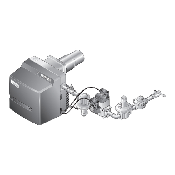
- Page 1 Installation and operating instruction Gas burner WG10…/0-D ZMI 83326002 1/2023-10...
-
Page 2: Table Of Contents
Installation and operating instruction Gas burner WG10…/0-D ZMI User instructions ...................... 5 1.1 Target group ........................ 5 1.2 Symbols in the manual .................... 5 1.3 Guarantee and Liability .................... 6 Safety ............................. 7 2.1 Designated application .................... 7 2.2 Safety symbols on the device ................... 7 2.3 ... - Page 3 Installation and operating instruction Gas burner WG10…/0-D ZMI 5.2 Electrical connection .................... 29 Operation .......................... 30 6.1 Operating panel ...................... 30 6.2 Display .......................... 32 6.2.1 Info level ....................... 33 6.2.2 Service level ...................... 34 6.2.3 Parameter level .................... 35 6.2.4 ...
- Page 4 Installation and operating instruction Gas burner WG10…/0-D ZMI 9.18 Replacing the fuse .................... 86 Troubleshooting ...................... 87 10.1 Procedures for fault conditions ................ 87 10.1.1 Display off ...................... 87 10.1.2 Display OFF ...................... 87 10.1.3 Display flashes .................... 88 10.1.4 ...
-
Page 5: User Instructions
Installation and operating instruction Gas burner WG10…/0-D ZMI 1 User instructions 1 User instructions This manual forms part of the equipment and must be kept on site. Translation of original operating instructions Carefully read the manual prior to working on the unit. 1.1 Target group The manual is intended for the operator and qualified personnel. -
Page 6: Guarantee And Liability
Weishaupt parts force majeure unauthorised modifications made to the unit the installation of additional components, which have not been tested with the... -
Page 7: Safety
Installation and operating instruction Gas burner WG10…/0-D ZMI 2 Safety 2 Safety 2.1 Designated application The burner is suitable for operation with process equipment systems. The combustion chambers must comply with EN 303 and EN 676. If the burner is not used in combustion chambers with dimensions that comply with EN 303 and EN 676, a safety assessment of combustion and flame stability during the individual process conditions, as well as the shutdown limits of the combustion system has to be carried out and documented. -
Page 8: Safety Measures
Installation and operating instruction Gas burner WG10…/0-D ZMI 2 Safety 2.4 Safety measures Safety relevant fault conditions must be eliminated immediately. Components, which show increased wear and tear or whose design lifespan is or will be exceeded prior to the next service should be replaced as a precaution. The design lifespan of the components is listed in the service plan [ch. 9.2]. -
Page 9: Gas Supply
Carry out soundness test after each service and fault rectification. 2.5 Alterations to the construction of the equipment All conversions require written approval from Max Weishaupt GmbH. No additional components may be fitted, which have not been tested for use with the equipment. -
Page 10: Product Description
Version Type of control: modulating, extended turndown ratio 3.2 Type and serial number The type and serial number on the type plate clearly identify the product. They are required by Weishaupt's customer service department. 1 Name plate Type: Ser. No.:... -
Page 11: Function
Installation and operating instruction Gas burner WG10…/0-D ZMI 3 Product description 3.3 Function 3.3.1 Air supply Air damper The air damper regulates the air quantity required for combustion. The combustion manager drives the air damper via actuator. At burner shutdown the actuator automatically closes the air damper. This reduces heat loss in the heat exchanger. -
Page 12: Gas Supply
Installation and operating instruction Gas burner WG10…/0-D ZMI 3 Product description 3.3.2 Gas supply Gas isolation valve 1 The gas isolation valve opens and shuts off the gas supply. Gas filter 2 The gas filter protects the subsequent valve train components from foreign particles. -
Page 13: Electrical Components
Installation and operating instruction Gas burner WG10…/0-D ZMI 3 Product description Control pressure regulator 8 The fan pressure influences the pressure at the outlet of the control regulator via an impulse line. If the fan pressure increases, the pressure at the outlet of the control regulator also increases and visa versa. -
Page 14: Program Sequence
Installation and operating instruction Gas burner WG10…/0-D ZMI 3 Product description 3.3.4 Program sequence The operating phases for commissioning the burner are shown on the display. Phase Function After the power supply has been switched on the combustion manager performs a self-test. TEST At heat demand, the actuators for the air damper and the gas butterfly valve drive to the reference point. - Page 15 Installation and operating instruction Gas burner WG10…/0-D ZMI 3 Product description W-FM 25 T1 T2 1234 1234 Ionisation electrode CLOSED position Air pressure switch Ignition position Temperature or pressure regulator Partial load Temperature or pressure regulator full load Full load Low gas pressure switch/valve proving gas Operating phase pressure switch...
-
Page 16: Inputs And Outputs
Air damper actuator Gas butterfly valve actuator Slot analogue module EM3/3 or Fieldbus module EM3/2 W-FM cover Not used Frequency converter for continuous running fan -weishaupt- Frequency converter Ignition unit double gas valve Not used Bridging plug No. 7 Gas meter (impulse generator) -
Page 17: Technical Data
–20 … +70 °C relative humidity max 80 %, no dew point Installation elevation max 2000 m Consultation with Weishaupt is required for higher installation elevation. 3.4.4 Permissible fuels Natural Gas E/LL Liquid Petroleum Gas B/P 17-124 83326002 1/2023-10 Ch... -
Page 18: Emissions
Installation and operating instruction Gas burner WG10…/0-D ZMI 3 Product description 3.4.5 Emissions Sound levels Dyad noise emission values Measured sound power level L (re 1 pW) dB(A) Uncertainty value K dB(A) Measured sound pressure level L (re 20 μPa) dB(A) Uncertainty value K dB(A) Determined to ISO 9614-2. -
Page 19: Rating
Installation and operating instruction Gas burner WG10…/0-D ZMI 3 Product description 3.4.6 Rating Combustion heat rating Natural Gas 4.5 … 60 kW 5.5 … 60 kW Capacity graph The capacity data given relates to an installation elevation of 0 m above sea level. For installation elevations above 0 m a capacity reduction of approx. 1 % per 100 m applies. -
Page 20: Dimensions
Installation and operating instruction Gas burner WG10…/0-D ZMI 3 Product description 3.4.7 Dimensions Burner Rp¾ –weishaupt– 330 mm 31,5 mm 115 mm 349 mm 1 210 mm without combustion head extension 2 140 mm without combustion head extension 310 mm with combustion head extension (100 mm) -
Page 21: Weight
Installation and operating instruction Gas burner WG10…/0-D ZMI 3 Product description Valve train Valve train 1 Rp½ approx. 436 mm Rp¾ approx. 537 mm approx. 587 mm Valve With thermal Without thermal train shut off device shut off device 2 Rp½ approx. -
Page 22: Installation
Installation and operating instruction Gas burner WG10…/0-D ZMI 4 Installation 4 Installation 4.1 Installation requirements Burner type and capacity graph Burner and heat exchanger must be matched. Check burner type and burner capacity. Installation location Prior to installation ensure that: sufficient space is available for normal and service position [ch. 3.4.7] sufficient combustion air is available and, if necessary, a ducted air intake is installed... -
Page 23: Burner Installation
Installation and operating instruction Gas burner WG10…/0-D ZMI 4 Installation 4.2 Burner installation Only valid in Switzerland When installing and operating in Switzerland the regulations of SVGW, VKF, and local and Cantonal regulations must be observed. Remove mixing head [ch. 9.3]. Remove burner flange 1 from burner housing. -
Page 24: Rotate Burner By 180° (Optional)
Installation and operating instruction Gas burner WG10…/0-D ZMI 4 Installation 4.2.1 Rotate burner by 180° (optional) Mount operating panel 1 on the opposite side of the housing. Mount fixing bracket 3 on the opposite side of the housing. Move the combustion manager upwards, using the holes (20 mm higher) on the retaining bracket. -
Page 25: Installation
Installation and operating instruction Gas burner WG10…/0-D ZMI 5 Installation 5 Installation 5.1 Gas supply Risk of explosion due to leaking gas Gas leaks can lead to a build-up of explosive gas/air mixture. With an ignition source present this can result in an explosion. Install gas supply with care. -
Page 26: Fit Impulse Line To The Control Pressure Regulator
Installation and operating instruction Gas burner WG10…/0-D ZMI 5 Installation 5.1.1 Fit impulse line to the control pressure regulator If required fit impulse line 1 to the control pressure regulator. 5.1.2 Installing the gas valve train Remove protective film and closing plug. Mount gas valve train free of stresses. -
Page 27: Fitting Gas Pressure Switch
Installation and operating instruction Gas burner WG10…/0-D ZMI 5 Installation 5.1.3 Fitting gas pressure switch Remove closing plug of test point 1. Fit sealing ring 2 supplied to the low gas pressure switch/valve proving gas pressure switch 3, ensuring sealing surfaces are clean. Fix gas pressure switch to the double gas valve using the screws supplied. -
Page 28: Carry Out Soundness Test Of Gas Supply Line And Vent
Installation and operating instruction Gas burner WG10…/0-D ZMI 5 Installation 5.1.6 Carry out soundness test of gas supply line and vent Only a competent installation company may carry out the soundness test and vent the gas pipe system. 28-124 83326002 1/2023-10 Ch... -
Page 29: Electrical Connection
Installation and operating instruction Gas burner WG10…/0-D ZMI 5 Installation 5.2 Electrical connection Risk of electric shock Working on the device when voltage is applied can lead to electric shock. Isolate the device from the power supply prior to starting any work. WARNING Safeguard against accidental restart. -
Page 30: Operation
Installation and operating instruction Gas burner WG10…/0-D ZMI 6 Operation 6 Operation 6.1 Operating panel [G] Gas Select gas butterfly valve actuator [–] Change values [L/A] Air Select air damper actuator [Enter] Reset burner Call up information: press for approx. 0.5 seconds: Info level press for approx. - Page 31 Installation and operating instruction Gas burner WG10…/0-D ZMI 6 Operation Operating status The exact operating status of the combustion manager can also be displayed. This simplifies determining the cause of a fault during troubleshooting [ch. 11.1]. Press and hold [–] and [+] simultaneously for approx. 3 seconds. The combustion manager changes to operating display.
-
Page 32: Display
Installation and operating instruction Gas burner WG10…/0-D ZMI 6 Operation 6.2 Display The display shows the current operating status and operating data. 1 Setting level activated 2 Start phase activated 3 Info level activated 4 Actuator runs CLOSED 5 Actuator runs OPEN 6 Burner in operation 7 Lockout 8 Service level activated... -
Page 33: Info Level
Installation and operating instruction Gas burner WG10…/0-D ZMI 6 Operation 6.2.1 Info level Burner data can be interrogated in the Info level . Press [Enter] for approx. 0.5 seconds. The Info level is activated. Press [Enter] to reach the next information. l,m³... -
Page 34: Service Level
Installation and operating instruction Gas burner WG10…/0-D ZMI 6 Operation 6.2.2 Service level The service level provides information about: actuator position of the individual operating points the most recent fault flame signal during burner operation Press [Enter] for approx. 2 seconds. The service level is activated. -
Page 35: Parameter Level
Installation and operating instruction Gas burner WG10…/0-D ZMI 6 Operation 6.2.3 Parameter level Settings at parameter level must only be carried out by qualified personnel. The parameter level can only be called up in Standby (OFF) mode. Press [+] and [Enter] keys simultaneously for approx. 2 seconds. The parameter level is activated. - Page 36 Installation and operating instruction Gas burner WG10…/0-D ZMI 6 Operation Pno. Parameters Setting range Factory setting Operating mode output X3:1 0: not activated 1: with pilot valve not interrupted 2: with pilot valve interrupted 3: Standard (external LPG valve) Flame sensor 0: ionisation electrode or flame sensor FLW 1: switch input (X3:14) 2: flame sensor QRB4 or flame sensor for continuous...
-
Page 37: Access Level
Installation and operating instruction Gas burner WG10…/0-D ZMI 6 Operation 6.2.4 Access level Settings at access level must only be carried out by qualified personnel. The configuration can be adapted relative to the burner type and/or version in the access level. In the parameter level, the display mode must be configured to 1, to enable access to parameters E0 … E3 [ch. 6.2.3]. -
Page 38: Linearisation
Installation and operating instruction Gas burner WG10…/0-D ZMI 6 Operation 6.3 Linearisation During commissioning it is possible to carry out linearisation of the operating points in gas operation. During linearisation a straight line is generated from the operating point displayed to P9. -
Page 39: Commissioning
Installation and operating instruction Gas burner WG10…/0-D ZMI 7 Commissioning 7 Commissioning 7.1 Prerequisite Commissioning must only be carried out by qualified personnel. Only correctly carried out commissioning ensures the operational safety. Do not operate the burner outside of the capacity graph [ch. 3.4.6]. Prior to commissioning ensure that: all assembly and installation work has been carried out correctly sufficient combustion air is available and, if necessary, a ducted air intake is... -
Page 40: Connect Measuring Devices
Installation and operating instruction Gas burner WG10…/0-D ZMI 7 Commissioning 7.1.1 Connect measuring devices Measuring device for ionisation current Remove ionisation cable from the plug coupling. Connect ammeter in series. Ionisation current Extraneous light detection from 1 μA Minimum ionisation current 5 μA Recommended ionisation current 9 … 15 μA... -
Page 41: Check Gas Connection Pressure
Installation and operating instruction Gas burner WG10…/0-D ZMI 7 Commissioning 7.1.2 Check gas connection pressure Minimum connection pressure Add the combustion chamber pressure in mbar to the minimum connection pressure. The connection pressure should not fall below 15 mbar. Determine minimum connection pressure for low pressure installations from table [ch. 7.1.5]. -
Page 42: Check Soundness Of Gas Valve Train
Installation and operating instruction Gas burner WG10…/0-D ZMI 7 Commissioning 7.1.3 Check soundness of gas valve train Carry out soundness test: prior to commissioning after all service and maintenance work First test phase Second and third test phase Test pressure 100 mbar ±10 % 100 mbar ±10 % Waiting time for pressure... - Page 43 Installation and operating instruction Gas burner WG10…/0-D ZMI 7 Commissioning Third test phase In the third phase the valve train section from the double gas valve up to the gas butterfly valve is tested. Remove mixing head [ch. 9.3]. Fit blanking plate 4. Fit mixing head.
- Page 44 Installation and operating instruction Gas burner WG10…/0-D ZMI 7 Commissioning Fourth test phase In the fourth test phase, the joint to the mixing head 1 is tested for soundness. The test phase can only be carried out during or after burner commissioning. A leak detecting spray or electronic gas detector should be used for testing.
-
Page 45: Purging The Gas Valve Train
Installation and operating instruction Gas burner WG10…/0-D ZMI 7 Commissioning 7.1.4 Purging the gas valve train The test burner must not be used to vent the gas valve train. If necessary, fit test nipple in front of valve 1 [ch. 7.1.3]. Open test nipple and connect an approved vent hose. -
Page 46: Preset Pressure Regulator
Installation and operating instruction Gas burner WG10…/0-D ZMI 7 Commissioning 7.1.5 Preset pressure regulator Determine setting pressure Add the combustion chamber pressure in mbar to the setting pressure into the gas butterfly valve. Determine setting pressure from the table and note down. The details given for calorific value H relate to 0 °C and 1013 mbar. - Page 47 Installation and operating instruction Gas burner WG10…/0-D ZMI 7 Commissioning Preset setting pressure Check setting pressure range of spring fitted. If necessary replace spring. Close gas isolation valve 2. Remove end cap 1. De-energise pressure regulator. Open test point into valve 1 and connect test gauge 4. Slowly open isolation valve and using the test burner 3 vent back pressure into valve 1.
-
Page 48: Setting Values
Installation and operating instruction Gas burner WG10…/0-D ZMI 7 Commissioning 7.1.6 Setting values Set mixing head relative to the combustion heat rating required. For this, the diffuser setting and the air damper setting should be matched. Determine diffuser and air damper settings Do not operate the burner outside of the capacity graph [ch. 3.4.6]. -
Page 49: Set Control Pressure Regulator
Installation and operating instruction Gas burner WG10…/0-D ZMI 7 Commissioning Set diffuser With dimension X = 0 mm the indicating bolt is flush with the cover of the nozzle assembly. Turn screw 1, until dimension X equals the value determined. 7.1.7 Set control pressure regulator Set the control pressure regulator according to the diffuser setting [ch. 7.1.6]. -
Page 50: Adjusting The Burner
Installation and operating instruction Gas burner WG10…/0-D ZMI 7 Commissioning 7.2 Adjusting the burner Risk of electric shock Touching the ignition device can lead to electric shock. Do not touch ignition device during the ignition process. WARNING Check flame signal during commissioning [ch. 7.1.1]. 1. - Page 51 Installation and operating instruction Gas burner WG10…/0-D ZMI 7 Commissioning Set gas butterfly setting of operating point P0 and operating point P1 depending on the diffuser setting. Natural Gas 1 Diffuser setting [mm] (dimension X) 2 Gas butterfly valve setting [°] 3 Operating point P0 4 Operating point P1 Liquid Petroleum Gas 1 Diffuser setting [mm] (dimension X)
- Page 52 Installation and operating instruction Gas burner WG10…/0-D ZMI 7 Commissioning Press [+] key. Factory setting operating point P1 (partial load) is displayed. Press and hold [G] and set gas butterfly valve setting to characteristic curve 4 using [–] or [+] keys. Press and hold [L/A] key and set air damper setting to 0.0 using the [–] key. Press [Enter] and [L/A] simultaneously.
- Page 53 Installation and operating instruction Gas burner WG10…/0-D ZMI 7 Commissioning 2. Check sequence of operation Open gas isolation valve. Pressure in gas valve train increases. Close isolation valve. Plug in bridging plug No. 7 on combustion manager. Burner starts. Valve proving is carried out. Speed standardisation is started.
- Page 54 Installation and operating instruction Gas burner WG10…/0-D ZMI 7 Commissioning 3. Preset setting pressure If a controlled shutdown or lockout occurs during setting: Briefly press [G] and [L/A] keys simultaneously. Press [+] key. Combustion manager changes to setting level. Open gas isolation valve. Briefly press [–] and [+] keys simultaneously.
- Page 55 Installation and operating instruction Gas burner WG10…/0-D ZMI 7 Commissioning 5. Adjust full load When adjusting, the ratings data given by the boiler manufacturer and the capacity graph of the burner should be observed [ch. 3.4.6]. Select speed at full load as low as possible, but not less than 90 %. Observe flame stability.
- Page 56 Installation and operating instruction Gas burner WG10…/0-D ZMI 7 Commissioning 7. Adjust ignition load The ignition speed must not be less than 70 %. Press [-] key. Burner drives to operating point P0 (ignition position). Check combustion values in operating point P0 (ignition position). Set O content of 6 …...
- Page 57 Installation and operating instruction Gas burner WG10…/0-D ZMI 7 Commissioning 9. Optimising the operating points Check combustion values. Press and hold [G] and optimise combustion values using [–] or [+] key. Press [+] key. Next operating point is initiated. Repeat steps at each operating point until P9 has been reached. Press [G] and [L/A] keys simultaneously.
-
Page 58: Set Pressure Switches
Installation and operating instruction Gas burner WG10…/0-D ZMI 7 Commissioning 7.3 Set pressure switches 7.3.1 Set gas pressure switch Set low gas pressure switch/valve proving Two setting criteria need to be met: 1. Criterion (monitoring gas connection pressure) Connect pressure measuring device to test point 1 of the low gas pressure switch. - Page 59 Installation and operating instruction Gas burner WG10…/0-D ZMI 7 Commissioning Set and check switch point The higher pressure from the two criteria is set at the gas pressure switch. Set gas pressure switch at the setting dial 2. Drive burner to 40 … 50 % of the capacity. Slowly close gas isolation valve.
-
Page 60: Set Air Pressure Switch
Installation and operating instruction Gas burner WG10…/0-D ZMI 7 Commissioning 7.3.2 Set air pressure switch The switch point must be checked and if necessary adjusted during commissioning. Connect pressure measuring device for differential pressure measurement. Start the burner. Carry out differential pressure measurement across the whole capacity range of the burner and determine the lowest differential pressure. -
Page 61: Concluding Work
Installation and operating instruction Gas burner WG10…/0-D ZMI 7 Commissioning 7.4 Concluding work Check control and safety devices. Remove gas pressure measuring devices and close all test points. Conclude valve proving of gas valve train (fourth test phase) [ch. 7.1.3]. Enter type and serial number into the text box [ch. 3.2]. Enter combustion values and settings in the commissioning record and/or test sheet. -
Page 62: Check Combustion
Installation and operating instruction Gas burner WG10…/0-D ZMI 7 Commissioning 7.5 Check combustion Determine excess air Slowly close air damper(s) in the relevant operating point, until the combustion limit is reached (CO content approx. 100 ppm). Measure and document O content. -
Page 63: Calculate Gas Throughput
Installation and operating instruction Gas burner WG10…/0-D ZMI 7 Commissioning 7.6 Calculate gas throughput Formula symbol Description Example values Operating volume [m – Volume measured at gas meter at current pressure and temperature (gas throughput). Standard volume [m – Volume gained by gas at 1013 mbar and 0 C. Conversion factor –... -
Page 64: Subsequent Optimisation Of Operating Points
Installation and operating instruction Gas burner WG10…/0-D ZMI 7 Commissioning 7.7 Subsequent optimisation of operating points If necessary, the combustion values can subsequently be corrected. Unplug bridging plug No. 7 on combustion manager. Combustion manager drives to Standby. Briefly press [–] and [+] simultaneously. Combustion manager changes to access level. -
Page 65: Shutdown
Installation and operating instruction Gas burner WG10…/0-D ZMI 8 Shutdown 8 Shutdown In the event of operational failure: Switch off burner. Close fuel shut off devices. 65-124 83326002 1/2023-10 Ch... -
Page 66: Servicing
The design lifespan of the components is listed in the service plan [ch. 9.2]. Weishaupt recommends a service contract is entered into to ensure regular inspections. 66-124... - Page 67 Installation and operating instruction Gas burner WG10…/0-D ZMI 9 Servicing The following components must only be replaced and must not be repaired: Combustion Manager Flame sensor Actuator double gas valve Pressure regulator Pressure switch Prior to every servicing Inform the operator about the extent of service work to be carried out. Switch off mains switch of installation and safeguard against accidental reactivation.
-
Page 68: Service Plan
Installation and operating instruction Gas burner WG10…/0-D ZMI 9 Servicing 9.2 Service plan Components Criteria / design lifespan Service procedure Ignition electrode Soiling Clean Damage / wear Replace [ch. 9.5] Recommendation: at least every 2 years Ignition cable Damage Replace Ionisation electrode Soiling Clean Damage / wear... -
Page 69: Removing And Refitting Mixing Head
Installation and operating instruction Gas burner WG10…/0-D ZMI 9 Servicing 9.3 Removing and refitting mixing head Observe notes on servicing [ch. 9.1]. Risk of explosion due to leaking gas It is possible for gas to leak out if the gasket 3 is seated incorrectly. Following work on the mixing head, ensure the gasket is clean and seated DANGER correctly, if necessary replace. -
Page 70: Set Mixing Head
Installation and operating instruction Gas burner WG10…/0-D ZMI 9 Servicing 9.4 Set mixing head Observe notes on servicing [ch. 9.1]. The distance between diffuser and flame tube front edge S1 cannot be measured with the burner mounted. This is only possible indirectly with dimension Lx when the mixing head is removed. -
Page 71: Set Ionisation And Ignition Electrodes
Installation and operating instruction Gas burner WG10…/0-D ZMI 9 Servicing 9.5 Set ionisation and ignition electrodes Observe notes on servicing [ch. 9.1]. Remove mixing head [ch. 9.3]. Undo screw 1. Set ignition electrode and tighten screw 2. Undo screw 2. Set ionisation electrode and tighten screw 2. 71-124 83326002 1/2023-10 Ch... -
Page 72: Service Position
Installation and operating instruction Gas burner WG10…/0-D ZMI 9 Servicing 9.6 Service position Observe notes on servicing [ch. 9.1]. The burner mounted rotated by 180° cannot be placed into the service position. Remove mixing head [ch. 9.3]. Remove cover 2 and remove plugs. Loosen operating panel 3 and rotate upwards. -
Page 73: Removing And Refitting Fan Wheel
Installation and operating instruction Gas burner WG10…/0-D ZMI 9 Servicing 9.7 Removing and refitting fan wheel Observe notes on servicing [ch. 9.1]. Personal protective equipment must be observed [ch. 2.4.1]. Removing Place housing cover into service position [ch. 9.6]. Remove grub screw 1 and remove fan wheel. Refitting Refit fan wheel in reverse order and ensure correct alignment on the motor shaft 2... -
Page 74: Replace Variable Speed Drive Sensor
Installation and operating instruction Gas burner WG10…/0-D ZMI 9 Servicing 9.8 Replace variable speed drive sensor Observe notes on servicing [ch. 9.1]. Removing Remove fan wheel [ch. 9.7]. Undo locknut 2 on intermediate motor flange. Remove variable speed drive sensor. Refitting Refit new VSD sensor in reverse order, whilst ensuring the VSD sensor 1 is flush with the motor flange 3. -
Page 75: Remove Frequency Converter
Installation and operating instruction Gas burner WG10…/0-D ZMI 9 Servicing 9.9 Remove frequency converter Observe notes on servicing [ch. 9.1]. Unplug plug 2 from burner motor. Remove cover 1 and remove plug FU. Remove plug number 3 from combustion manager. Undo screws 3 and remove frequency converter. 75-124 83326002 1/2023-10 Ch... -
Page 76: Remove Burner Motor
Installation and operating instruction Gas burner WG10…/0-D ZMI 9 Servicing 9.10 Remove burner motor Observe notes on servicing [ch. 9.1]. Remove frequency converter [ch. 9.9]. Remove fan wheel [ch. 9.7]. Unplug plug number 11. Disconnect + and - hoses. Undo screws 1 and remove air pressure switch. Hold motor and remove screws 2. -
Page 77: Removing And Refitting Air Damper Actuator
Installation and operating instruction Gas burner WG10…/0-D ZMI 9 Servicing 9.11 Removing and refitting air damper actuator Observe notes on servicing [ch. 9.1]. Removing Remove frequency converter [ch. 9.9]. Remove actuator plug 4 from combustion manager. Remove screws 3. Remove actuator and shaft 2. Refitting Damage to the actuator caused by turning the hub Actuator could be damaged. -
Page 78: Removing And Refitting Angle Drive
Installation and operating instruction Gas burner WG10…/0-D ZMI 9 Servicing 9.12 Removing and refitting angle drive Observe notes on servicing [ch. 9.1]. Removing Remove air damper actuator [ch. 9.11]. Remove frame 1. Remove angle drive 2. Refitting Remove intake housing. Open air damper 3 until position 4 has been reached and hold tight. Fit angle drive to shaft. -
Page 79: Removing And Refitting Gas Butterfly Valve Actuator
Installation and operating instruction Gas burner WG10…/0-D ZMI 9 Servicing 9.13 Removing and refitting gas butterfly valve actuator Observe notes on servicing [ch. 9.1]. Removing Remove actuator plug 1 from combustion manager. Remove screws 2. Remove actuator. Refitting Damage to the actuator caused by turning the hub Actuator could be damaged. -
Page 80: Removing And Refitting Gas Butterfly Valve
Installation and operating instruction Gas burner WG10…/0-D ZMI 9 Servicing 9.14 Removing and refitting gas butterfly valve Observe notes on servicing [ch. 9.1]. Removing Remove screws 4. Unscrew fitting 3. Remove mixing head [ch. 9.3]. Remove screws 1 and remove gas butterfly valve 2. Refitting Refit gas butterfly valve 2 in reverse order, secure flange to double gas valve whilst ensuring correct seating of the O ring 5 on the flange. -
Page 81: Removing And Refitting Air Regulator
Installation and operating instruction Gas burner WG10…/0-D ZMI 9 Servicing 9.15 Removing and refitting air regulator Observe notes on servicing [ch. 9.1]. Removing Remove bolts 1. Remove burner from heat exchanger [ch. 4.2]. Remove actuator plug 6. Remove bolts 2. Remove intake housing 5. Remove bolts 4. -
Page 82: Replacing Double Gas Valve Coil
Installation and operating instruction Gas burner WG10…/0-D ZMI 9 Servicing 9.16 Replacing double gas valve coil Observe notes on servicing [ch. 9.1]. Ensure correct voltage and solenoid number when replacing the solenoid coil. Undo screws 1. Remove cap 2. Remove metal plate 4. Replace solenoid coil 3. -
Page 83: Replacing The Combustion Manager
Installation and operating instruction Gas burner WG10…/0-D ZMI 9 Servicing 9.17 Replacing the combustion manager Observe notes on servicing [ch. 9.1]. Unplug all plugs. Undo screws 1. Push combustion manager upwards and replace. Connect all plugs again. Preset combustion manager Unplug bridging plug No. 7 on combustion manager. Switch on voltage supply. - Page 84 Installation and operating instruction Gas burner WG10…/0-D ZMI 9 Servicing Press [G] and [L/A] simultaneously. Combustion manager changes to access level. Press [+]. Setting level (parameter E0) is displayed. Adopt value 0 (single fuel burner) and if necessary adjust using [Enter] and [–] key.
- Page 85 Installation and operating instruction Gas burner WG10…/0-D ZMI 9 Servicing Determine the operating points from the sticker 1. Set the burner using these operating points and adjust [ch. 7.2]. Brennereinstellung Datum: Stauscheiben- einstellung: Gaseinstelldruck bei Großlast: mbar Einstellungen am Feuerungsmanager: Voreinstellung Luftklappe bei Großlast (P9): °...
-
Page 86: Replacing The Fuse
Installation and operating instruction Gas burner WG10…/0-D ZMI 9 Servicing 9.18 Replacing the fuse Observe notes on servicing [ch. 9.1]. Unplug connection plug from combustion manager. Replace fuse (T6.3H, IEC 127-2/5). 1 Replacement fuse 86-124 83326002 1/2023-10 Ch... -
Page 87: Troubleshooting
Top up water. exchanger has triggered Reset low water safety interlock on heat exchanger. Notify your heating contractor or Weishaupt Customer Service if the problem occurs repeatedly. 10.1.2 Display OFF The following faults may be corrected by the operator: Fault... -
Page 88: Display Flashes
Installation and operating instruction Gas burner WG10…/0-D ZMI 10 Troubleshooting 10.1.3 Display flashes A burner fault has occurred. The burner is in lockout. The error code is displayed flashing. Read error code, e. g. A7h. Rectify cause of fault [ch. 10.2]. Reset Damage resulting from incorrect fault repair Incorrect fault repair can cause damage to the equipment and injure personnel. -
Page 89: Detailed Fault Codes
Installation and operating instruction Gas burner WG10…/0-D ZMI 10 Troubleshooting 10.1.4 Detailed fault codes Additional information, which breaks down the error in more detail, can be displayed by pressing a button. The first detailed fault code and the second detailed fault code are only relevant for the following faults: 1. -
Page 90: Rectifying Faults
Installation and operating instruction Gas burner WG10…/0-D ZMI 10 Troubleshooting 10.2 Rectifying faults Faults must only be rectified by qualified personnel: Fault codes Cause Rectification 01h … 02h Internal unit fault Interrupt the voltage supply temporarily Reset the burner, if fault reoccurs replace the 05h …... - Page 91 Installation and operating instruction Gas burner WG10…/0-D ZMI 10 Troubleshooting Faults must only be rectified by qualified personnel: Fault codes Cause Rectification Switch off via PC Software – Second detailed fault code: A1h Check Bus address Invalid Bus address Second detailed fault code: A5h Check configuration at output B4 Configuration at output B4 incorrect Second detailed fault code: A6h...
- Page 92 Installation and operating instruction Gas burner WG10…/0-D ZMI 10 Troubleshooting Faults must only be rectified by qualified personnel: Fault codes Cause Rectification Plugs of actuators for gas and air mixed up Change over plugs Tolerance fault actuator Check freedom of movement of air damper and / or angle drive and gas butterfly valve Replace actuator Actuator does not drive to reference point...
- Page 93 Installation and operating instruction Gas burner WG10…/0-D ZMI 10 Troubleshooting Faults must only be rectified by qualified personnel: Fault codes Cause Rectification No flame signal after safety time Set ignition electrode [ch. 9.5] Check the ignition unit and replace if necessary Check solenoid valve coil and cable, replace if necessary Check the ionisation electrode and cable,...
- Page 94 Installation and operating instruction Gas burner WG10…/0-D ZMI 10 Troubleshooting Faults must only be rectified by qualified personnel: Fault codes Cause Rectification Connection to actuator faulty Rectify the fault using the following procedure: Interrupt voltage supply Plug in plug on combustion manager correctly Fit W-FM cover [ch. 3.3.5].
-
Page 95: Operating Problems
Installation and operating instruction Gas burner WG10…/0-D ZMI 10 Troubleshooting 10.3 Operating problems Faults must only be rectified by qualified personnel: Observation Cause Rectification Poor start behaviour of burner Mixing pressure too high Reduce mixing pressure in ignition position Ignition electrode set incorrectly Set ignition electrode [ch. 9.5] Mixing head set incorrectly Set mixing head [ch. 9.4]... -
Page 96: Technical Documentation
Installation and operating instruction Gas burner WG10…/0-D ZMI 11 Technical documentation 11 Technical documentation 11.1 Program sequence The exact operating status of the combustion manager can also be displayed. Activate operating status [ch. 6]. Operating phase Operating status Condition / function Fault present F .. - Page 97 Installation and operating instruction Gas burner WG10…/0-D ZMI 11 Technical documentation Operating phase Operating status Condition / function Restart interlock 16 ..Reference search actuator - air damper and gas butterfly valve Test gas butterfly valve actuator 105° Drive to Standby position Internal sequence Insufficient gas, low gas pressure switch (X3:14) OFFGd...
-
Page 98: Conversion Table Unit Of Pressure
Installation and operating instruction Gas burner WG10…/0-D ZMI 11 Technical documentation 11.2 Conversion table unit of pressure Pascal 0.1 mbar 0.01 0.00001 1 mbar 0.0001 10 mbar 1 000 0.001 100 mbar 10 000 0.01 1 bar 100 000 1 000 10 bar 1 000 000 10 000... -
Page 99: Appliance Categories
5.1.2, table 5 are used to provide the evidence of service performance of the burner during type testing. As -Weishaupt- gas and dual fuel burners fulfil these requirements completely, the appliance category, as well as the test gases used with the permissible connection pressure range, are listed on the name plate when labelling the burner to point 6.2 . - Page 100 Installation and operating instruction Gas burner WG10…/0-D ZMI 11 Technical documentation Alternative appliance category to I2R Country of Appliance category Test gas Connection pressure destination [mbar] AT (Austria) G 20 BE (Belgium) G 20 Pressure range 20⇆25 2E(S) 2E(R) CH (Schwitzerland) G 20 CZ (Czech Republic) I G 20...
- Page 101 Installation and operating instruction Gas burner WG10…/0-D ZMI 11 Technical documentation Alternative appliance category to I3R Country of Appliance category Test gas Connection pressure destination [mbar] AT (Austria) G 30, G 31 30 / 50 3B/P BE (Belgium) G 30, G 31 Pressure range 28-30⇆37 3B/P CH (Schwitzerland)
- Page 102 Installation and operating instruction Gas burner WG10…/0-D ZMI 11 Technical documentation Alternative appliance category to II2R/3R Country of Appliance category Test gas Connection Test gas Connection pressure destination pressure [mbar] [mbar] AT (Austria) , II G 20 G 30, G 31 30 / 50 2H3B/P 2H3P BE (Belgium)
- Page 103 Installation and operating instruction Gas burner WG10…/0-D ZMI 11 Technical documentation Country of Appliance category Test gas Connection Test gas Connection pressure destination pressure [mbar] [mbar] RO (Romania) , II , II G 20 20 / 25 G 30, G 31 30 2H3B/P 2H3P 2L3P...
-
Page 104: Project Planning
Installation and operating instruction Gas burner WG10…/0-D ZMI 12 Project planning 12 Project planning 12.1 Continuous running fan or post-purge Fire hazard due to failure of the combustion air fan Failure of the combustion air fan (e.g. due to a power failure or defective motor) during operation with continuous running fan or increased post-purge may result in back radiation or hot flue gases flowing back into the burner housing. - Page 105 Installation and operating instruction Gas burner WG10…/0-D ZMI 12 Project planning 105-124 83326002 1/2023-10 Ch...
-
Page 106: Spares
Installation and operating instruction Gas burner WG10…/0-D ZMI 13 Spares 13 Spares 1.01 1.18 1.02 1.15 1.16 1.06 1.08 1.07 1.17 1.16 1.14 1.04 1.11 1.14 1.03 1.09 1.03 1.12 1.05 1.12 1.10 1.13 106-124 83326002 1/2023-10 Ch... - Page 107 Installation and operating instruction Gas burner WG10…/0-D ZMI 13 Spares Pos. Description Order No. 1.01 Cover 232 110 01 112 1.02 Screw M8 x 16 ISO 10642 404 412 1.03 Mounting bracket for cover 241 400 01 207 1.04 Burner housing 241 110 01 307 1.05 Intake housing complete...
- Page 108 Installation and operating instruction Gas burner WG10…/0-D ZMI 13 Spares 2.21 2.11 2.12 2.10 2.09 2.13 2.05 2.07 2.14 2.22 2.02 2.05 2.08 2.17 2.24 2.15 2.26 2.16 2.31 2.01 2.33 2.19 2.20 2.23 2.32 2.18 2.27 2.06 2.29 2.25 2.04 2.30 2.03...
- Page 109 Installation and operating instruction Gas burner WG10…/0-D ZMI 13 Spares Pos. Description Order No. 2.01 Motor W-PM03/S-4 WG10 ZMI 232 110 08 022 - Motor W-PM03/S-4 W10 652 162 - Intermediate motor flange WG10/20 ZMI 232 110 01 147 - Screw M4 x 10 Torx-Plus 20IP metr. 409 323 2.02 Screw M4 x 10 Torx-Plus 20IP metr.
- Page 110 Installation and operating instruction Gas burner WG10…/0-D ZMI 13 Spares 3.01 3.03 3.06 3.02 3.07 3.04 3.05 3.17 3.16 3.15 3.15 3.11 3.08 3.12 3.13 3.10 3.14 3.09 3.19 3.20 3.18 110-124 83326002 1/2023-10 Ch...
- Page 111 Installation and operating instruction Gas burner WG10…/0-D ZMI 13 Spares Pos. Description Order No. 3.01 Mixing head ZMI complete (Natural gas) – Standard 232 110 14 252 – extended by 100 mm* 230 110 14 852 – extended by 200 mm* 230 110 14 862 –...
- Page 112 Installation and operating instruction Gas burner WG10…/0-D ZMI 13 Spares 4.16 4.17 4.18 4.03 4.01 4.14 4.15 4.08 4.07 4.02 4.04 4.05 4.06 4.19 4.09 4.21 4.22 4.11 4.23 4.10 4.20 4.13 4.12 112-124 83326002 1/2023-10 Ch...
- Page 113 Installation and operating instruction Gas burner WG10…/0-D ZMI 13 Spares Pos. Description Order No. 4.01 Combustion manager W-FM 25 / 230 V – intermittent operation without O trim 600 487 – Continuous operation / O trim (PO-O2) 600 489 4.02 Micro fuse T6.3H, IEC 127-2/5 483 011 22 457 4.03...
- Page 114 Installation and operating instruction Gas burner WG10…/0-D ZMI 13 Spares 5.04 ½'' ¾'' 5.01 5.03 5.07 5.07 5.05 5.02 5.07 5.05 5.21* 5.06 5.07 5.11 5.13 5.12 5.14 5.08 5.12 5.16 5.15 5.09 5.11 5.10 5.20 5.07 5.19 5.18 5.07 5.07 5.17 114-124...
- Page 115 Installation and operating instruction Gas burner WG10…/0-D ZMI 13 Spares Pos. Description Order No. 5.01 Double nipple R¾ x 80 139 000 26 787 5.02 T-piece B1 R¾ x ½ x ¾ 453 629 5.03 Reducing nipple N4-2 R½ x G¼ 151 337 26 647 5.04 Pressure test nipple G¼...
- Page 116 Installation and operating instruction Gas burner WG10…/0-D ZMI 13 Spares 5.04 ½'' ¾'' 5.01 5.03 5.07 5.07 5.05 5.02 5.07 5.05 5.21* 5.06 5.07 5.11 5.13 5.12 5.14 5.08 5.12 5.16 5.15 5.09 5.11 5.10 5.20 5.07 5.19 5.18 5.07 5.07 5.17 116-124...
- Page 117 Installation and operating instruction Gas burner WG10…/0-D ZMI 13 Spares Pos. Description Order No. 5.20 Ball valve – 998NG-½-CE-TAE 454 595 – 998NG-¾-CE-TAE 454 596 – 998NG-1-CE-TAE 454 597 5.21 Max. pressure switch GW50* 691 381 * Only in conjunction with high gas pressure switch 117-124 83326002 1/2023-10 Ch...
-
Page 118: Notes
Installation and operating instruction Gas burner WG10…/0-D ZMI 14 Notes 14 Notes 118-124 83326002 1/2023-10 Ch... - Page 119 Installation and operating instruction Gas burner WG10…/0-D ZMI 14 Notes 119-124 83326002 1/2023-10 Ch...
-
Page 120: Key Word Index
Installation and operating instruction Gas burner WG10…/0-D ZMI 15 Key word index 15 Key word index Ducted air intake ............ 7, 19 Access level .............. 31, 37 Actuator................. 77 Adjust.................. 64 Electrical connection............ 29 Air damper .......... 11, 48, 77, 78, 81 Electrical data .............. 17 Air number ................ 62 Electrode................ 71 Air pressure ................ 63... - Page 121 Installation and operating instruction Gas burner WG10…/0-D ZMI 15 Key word index Impulse line............ 13, 26, 27 Partial load................ 57 Indicating bolt .............. 49 Pascal .................. 98 Info button................ 30 Personal protective equipment .......... 8 Info level ................ 33 Post purge air damper setting ......... 36 Initialisation time .............. 15 Post-purge time.............. 15 Inputs .................. 16...
- Page 122 Installation and operating instruction Gas burner WG10…/0-D ZMI 15 Key word index Type .................. 10 Type key ................ 10 Type of Gas.............. 17, 99 Unit of pressure.............. 98 Valve proving................ 12 Valve proving gas pressure switch ......... 58 Valve train .............. 25, 26, 46 VisionBox ................ 31 Voltage supply .............. 17 VSD sensor ..............
- Page 123 83326002 1/2023-10 Ch...
- Page 124 Max Weishaupt GmbH · 88475 Schwendi Weishaupt close by? Addresses, telephone numbers etc. can be found at www.weishaupt.de We reserve the right to make changes. All rights reserved. The complete program: Reliable technology and prompt, professional service W Burners up to 700 kW...
Need help?
Do you have a question about the WG10 0-D ZMI Series and is the answer not in the manual?
Questions and answers