Table of Contents
Advertisement
Quick Links
Advertisement
Table of Contents

Related Manuals for Weishaupt WL40Z-A 1LN


Summary of Contents for Weishaupt WL40Z-A 1LN
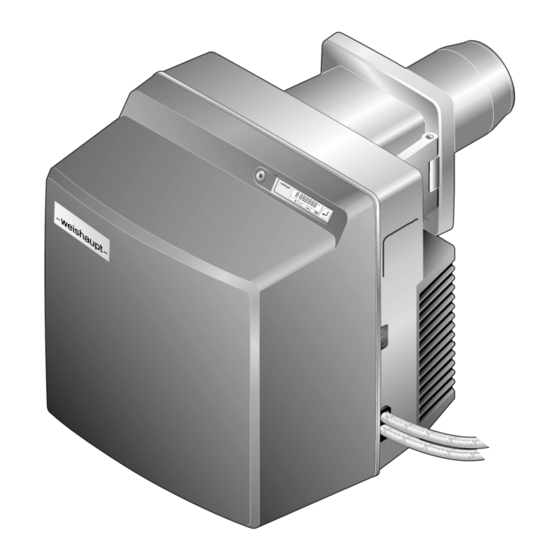
- Page 1 Installation and operating instruction Oil burner WL40Z-A 1LN 83298902 2/2019-05...
-
Page 2: Table Of Contents
Installation and operating instruction Oil burner WL40Z-A 1LN User instructions ...................... 5 1.1 Target group ........................ 5 1.2 Symbols .......................... 5 1.3 Guarantee and Liability .................... 6 Safety ............................. 7 2.1 Designated application .................... 7 2.2 Safety measures ...................... 7 2.2.1 Normal operation .................... 7 2.2.2 ... - Page 3 Installation and operating instruction Oil burner WL40Z-A 1LN Commissioning ...................... 36 7.1 Prerequisite ......................... 36 7.1.1 Connect measuring devices ................ 36 7.1.2 Set minimum oil pressure switch (optional) .......... 37 7.1.3 Setting values ...................... 38 7.2 Adjusting the burner .................... 40 7.2.1 ...
- Page 4 Installation and operating instruction Oil burner WL40Z-A 1LN Spares .......................... 92 Notes .......................... 106 Key word index ...................... 108 4-112 83298902 2/2019-05 La...
-
Page 5: User Instructions
Installation and operating instruction Oil burner WL40Z-A 1LN 1 User instructions 1 User instructions This manual forms part of the equipment and must be kept on site. Translation of original Carefully read the manual prior to working on the unit. -
Page 6: Guarantee And Liability
Weishaupt parts, force majeure, unauthorised modifications made to the unit, the installation of additional components, which have not been tested with the... -
Page 7: Safety
EN 60900 should be used. 2.3 Alterations to the construction of the equipment All conversions require written approval from Max Weishaupt GmbH. No additional components may be fitted, which have not been tested for use with the equipment. -
Page 8: Noise Emission
Installation and operating instruction Oil burner WL40Z-A 1LN 2 Safety 2.4 Noise emission The noise emissions are determined by the acoustic behaviour of all components fitted to the combustion system. Prolonged exposure to high noise levels can lead to loss of hearing. Provide oper- ating personnel with protective equipment. -
Page 9: Product Description
Installation and operating instruction Oil burner WL40Z-A 1LN 3 Product description 3 Product description 3.1 Type key WL40Z-A 1LN Type: W burner Fuel: Oil EL Size Version: two stage Construction Version: LowNO 3.2 Serial number The serial number on the name plate identifies the product. This is required by Weishaupt's customer service department. -
Page 10: Function
Installation and operating instruction Oil burner WL40Z-A 1LN 3 Product description 3.3 Function 3.3.1 Air supply Air damper The air damper regulates the air quantity required for combustion. The combustion manager drives the air damper via actuator. At burner shutdown the air damper closes automatically. -
Page 11: Oil Supply
Installation and operating instruction Oil burner WL40Z-A 1LN 3 Product description 3.3.2 Oil supply Oil pump The pump draws the oil through the supply line and carries it under pressure to the oil nozzle. The pressure regulating valve keeps the oil pressure constant. -
Page 12: Electrical Components
Installation and operating instruction Oil burner WL40Z-A 1LN 3 Product description 3.3.3 Electrical components Combustion Manager The combustion manager W-FM is the control unit of the burner. It controls the sequence of operation and monitors the flame. Operating panel The values and parameters of the combustion manager can be displayed and changed at the operating panel. - Page 13 Installation and operating instruction Oil burner WL40Z-A 1LN 3 Product description W-FM 25 T1 T2 P11P13 1234 Flame sensor Operating point P0 (ignition position) Temperature or pressure regulator Operating point P1 (stage 1) Temperature or pressure regulator stage 2 Operating point P2 (solenoid valve stage 2) Temperature or pressure limiter Operating point P9 (stage 2)
-
Page 14: Inputs And Outputs
Installation and operating instruction Oil burner WL40Z-A 1LN 3 Product description 3.3.5 Inputs and outputs Observe wiring diagram supplied. TWI interface (VisionBox, accessory) sensor (accessory) Speed signal (Namur) Frequency converter Operating panel Air damper actuator Coded plug (black) Slot for analogue module EM3/3 or fieldbus module EM3/2... -
Page 15: Technical Data
Installation and operating instruction Oil burner WL40Z-A 1LN 3 Product description 3.4 Technical data 3.4.1 Approval data PIN 2014/68/EU Z-IS-TAF-MUC-14-05-376456-004 DIN CERTCO 5G820 Basic standards EN 267:2011 Additional standards, see EU conformity certifica- tion. 3.4.2 Electrical data Mains voltage / mains frequency... -
Page 16: Emissions
Installation and operating instruction Oil burner WL40Z-A 1LN 3 Product description 3.4.5 Emissions Flue gas To EN 267 the burner complies with emission class 3. The NO values are influenced by: combustion chamber dimensions flue gas system fuel combustion air (temperature and humidity) -
Page 17: Rating
Installation and operating instruction Oil burner WL40Z-A 1LN 3 Product description 3.4.6 Rating Combustion heat rating Combustion heat rating 120 … 355 kW 10 … 30 kg/h Combustion head W40/1LN The oil throughput data relates to a calorific value of 11.9 kWh/kg for fuel oil EL. -
Page 18: Dimensions
Installation and operating instruction Oil burner WL40Z-A 1LN 3 Product description 3.4.7 Dimensions Burner 72 mm 450 mm 577 mm 615 mm 1 231 mm without combustion head extension 331 mm with combustion head extension (100 mm) 3.4.8 Weight approx. 37 kg... -
Page 19: Installation
Installation and operating instruction Oil burner WL40Z-A 1LN 4 Installation 4 Installation 4.1 Installation conditions Burner type and capacity graph Burner and heat exchanger must be matched. Check burner type and burner capacity. Installation location Prior to installation ensure that: sufficient space is available for normal and service position [ch. 3.4.7],... -
Page 20: Selecting A Nozzle
Installation and operating instruction Oil burner WL40Z-A 1LN 4 Installation 4.2 Selecting a nozzle Determine nozzle size. Load distribution The load distribution of the burner is made via a pressure change-over on the oil pump. Generally, stage 1 takes on approx. 65 % of the maximum oil throughput, a different distribution may be necessary. - Page 21 Installation and operating instruction Oil burner WL40Z-A 1LN 4 Installation Nozzle selection table Different load values are possible due to tolerances. Stage 1 Burner capacity [kW] at pump pressure Nozzle size [gph] 10 bar 11 bar 12 bar 2.50 –...
-
Page 22: Burner Installation
Installation and operating instruction Oil burner WL40Z-A 1LN 4 Installation 4.3 Burner installation Pay attention to local regulations for lifting and carrying loads [ch. 3.4.8]. Remove screws 1. Remove pin 4. Remove burner flange 3 from burner housing. It is possible to install the burner rotated by 180 if space is limited. This requires conversion measures [ch. 4.3.1]. -
Page 23: Rotate Burner By 180° (Optional)
Installation and operating instruction Oil burner WL40Z-A 1LN 4 Installation 4.3.1 Rotate burner by 180° (optional) Mount operating panel 1 on the opposite side of the housing. Mount fixing bracket 3 on the opposite side of the housing. Remove pressure hoses 6. Remove oil pump 7 and install rotated by 180° [ch. 9.10]. -
Page 24: Installation
Installation and operating instruction Oil burner WL40Z-A 1LN 5 Installation 5 Installation 5.1 Oil supply Observe EN 12514-2, DIN 4755, TRÖI and local regulations. Check conditions for oil pump Suction resistance max 0.4 bar Supply pressure max 2 bar Supply temperature max 60 °C... - Page 25 Installation and operating instruction Oil burner WL40Z-A 1LN 5 Installation Connect oil supply and observe: do not twist oil hoses avoid mechanical tension consider length of hose required for the service position, do not kink oil hoses (curve radius 1 of 75 mm must be maintained).
-
Page 26: Electrical Connection
Installation and operating instruction Oil burner WL40Z-A 1LN 5 Installation 5.2 Electrical connection Risk of electric shock Working on the device when voltage is applied can lead to electric shock. Isolate the device from the power supply prior to starting any work. - Page 27 Installation and operating instruction Oil burner WL40Z-A 1LN 5 Installation Separate supply line for burner motor (not with variable speed drive) Observe wiring diagram supplied. Plug supply line for burner motor into connection plug 1 of the contactor. External fuse of separate supply line:...
-
Page 28: Operation
Installation and operating instruction Oil burner WL40Z-A 1LN 6 Operation 6 Operation 6.1 Operating panel [–] Change values [L/A] Air Select air damper actuator [Enter] Reset burner: call up information press for approx. 0.5 seconds: Info level press for approx. 2 seconds: Service level... - Page 29 Installation and operating instruction Oil burner WL40Z-A 1LN 6 Operation Operating status The exact operating status of the combustion manager can also be displayed. This simplifies determining the cause of a fault during troubleshooting [ch. 11.1]. Press and hold [–] and [+] simultaneously for approx. 3 seconds.
-
Page 30: Display
Installation and operating instruction Oil burner WL40Z-A 1LN 6 Operation 6.2 Display The display shows the current operating statuses and operating data. 1 Setting level activated 2 Start phase activated 3 Info level activated 4 Actuator runs CLOSED 5 Actuator runs OPEN... -
Page 31: Info Level
Installation and operating instruction Oil burner WL40Z-A 1LN 6 Operation 6.2.1 Info level Burner data can be interrogated in the Info level . Press [Enter] for approx. 0.5 seconds. The Info level is activated. Press [Enter] to reach the next information. -
Page 32: Service Level
Installation and operating instruction Oil burner WL40Z-A 1LN 6 Operation 6.2.2 Service level The service level gives information about: Actuator position of the individual operating points, the most recent fault, flame signal during burner operation. Press [Enter] for approx. 2 seconds. -
Page 33: Parameter Level
Installation and operating instruction Oil burner WL40Z-A 1LN 6 Operation 6.2.3 Parameter level The parameter level can only be called up in Standby (OFF) mode. Press [+] and [Enter] keys simultaneously for approx. 2 seconds. The parameter level is activated. - Page 34 Installation and operating instruction Oil burner WL40Z-A 1LN 6 Operation Pno. Parameters Setting range Factory setting Display mode 0: E-parameter is not activated in the access level 1: E-parameter is activated in the access level Settings 2 and 3 are required for O...
-
Page 35: Access Level
Installation and operating instruction Oil burner WL40Z-A 1LN 6 Operation 6.2.4 Access level In the access level, the configuration can be adapted relative to the burner type or version. In the parameter level, the display mode must be configured to 1, to enable access to parameters E0 … E4. -
Page 36: Commissioning
Installation and operating instruction Oil burner WL40Z-A 1LN 7 Commissioning 7 Commissioning 7.1 Prerequisite Commissioning must only be carried out by qualified personnel. Only correctly carried out commissioning ensures the operational safety. Prior to commissioning ensure that: all assembly and installation work has been carried out correctly,... -
Page 37: Set Minimum Oil Pressure Switch (Optional)
Installation and operating instruction Oil burner WL40Z-A 1LN 7 Commissioning Oil pressure measuring devices on oil pump Vacuum gauge for suction resistance/supply pressure. Pressure gauge for pump pressure. Oil leakage from oil pressure measuring devices due to constant load Oil pressure measuring devices could be damaged and cause environmental pollu- tion through leakage. -
Page 38: Setting Values
Installation and operating instruction Oil burner WL40Z-A 1LN 7 Commissioning 7.1.3 Setting values Set mixing head relative to the combustion heat rating required. For this, the dif- fuser setting and the air damper setting should be matched. Determine diffuser setting and air damper setting Do not operate the burner outside of the capacity graph. - Page 39 Installation and operating instruction Oil burner WL40Z-A 1LN 7 Commissioning Set diffuser With dimension X = 0mm the indicating bolt is flush with nozzle assembly cover. Turn screw 1, until dimension X equals the value determined. Determine mixing pressure Determine the mixing pressure required for the preset combustion heat rating from the diagram and note down.
-
Page 40: Adjusting The Burner
Installation and operating instruction Oil burner WL40Z-A 1LN 7 Commissioning 7.2 Adjusting the burner 7.2.1 Burner without variable speed drive Risk of electric shock Touching the ignition device can lead to electric shock. Do not touch ignition device during the ignition process. - Page 41 Installation and operating instruction Oil burner WL40Z-A 1LN 7 Commissioning Preset P1 Press [+] key. Factory setting operating point P1 (stage 1) is displayed. Press and hold [L/A] key and set air damper setting determined using the [–] or [+] key [ch. 7.1.3]. Preset P0 Press [+] key.
- Page 42 Installation and operating instruction Oil burner WL40Z-A 1LN 7 Commissioning 2. Adjusting the operating points Open oil shut off devices. If a controlled shutdown or lockout occurs during setting: Briefly press [G] and [L/A] keys simultaneously. Press [+] key. Combustion manager changes to setting level.
- Page 43 Installation and operating instruction Oil burner WL40Z-A 1LN 7 Commissioning Set pump pressure for stage 2 The pump pressure must be set according to the nozzle selected [ch. 4.2]. Check pump pressure at pressure gauge. Set pressure using pressure regulating screw 1: increase pressure: clockwise rotation, decrease pressure: anticlockwise rotation.
- Page 44 Installation and operating instruction Oil burner WL40Z-A 1LN 7 Commissioning Adjust P0 Press [-] key. Burner drives to operating point P0 (ignition position). Press and hold [L/A] key and set P0 to the same value as P1 using the [-] or [+] key.
- Page 45 Installation and operating instruction Oil burner WL40Z-A 1LN 7 Commissioning Adjust P2 and P3 Press [+] key. Switch off point stage 2 when running closed (P2) is displayed. Set switch off point stage 2 when running closed (P2) to approx. 1/3 of the setting movement between P1 and P9.
-
Page 46: Burner With Variable Speed Drive (Optional)
Installation and operating instruction Oil burner WL40Z-A 1LN 7 Commissioning 7.2.2 Burner with variable speed drive (optional) Risk of electric shock Touching the ignition device can lead to electric shock. Do not touch ignition device during the ignition process. DANGER During commissioning check: suction resistance or flow pressure of oil pump [ch. 5.1],... - Page 47 Installation and operating instruction Oil burner WL40Z-A 1LN 7 Commissioning Preset P1 Press [+] key. Factory setting operating point P1 (stage 1) is displayed. Press and hold [L/A] key and set air damper setting determined using the [–] or [+] key [ch. 7.1.3]. Press [Enter] and [L/A] simultaneously.
- Page 48 Installation and operating instruction Oil burner WL40Z-A 1LN 7 Commissioning Preset P2 and P3 Press [+] key. Factory setting operating point P2 (switch off point stage 2 when running closed) is displayed. Press and hold [L/A] key and set P2 approx. 3 … 8° above P1 using the [–] or [+] key.
- Page 49 Installation and operating instruction Oil burner WL40Z-A 1LN 7 Commissioning 2. Adjusting the operating points Open oil shut off devices. If a controlled shutdown or lockout occurs during setting: Briefly press [G] and [L/A] keys simultaneously. Press [+] key. Combustion manager changes to setting level.
- Page 50 Installation and operating instruction Oil burner WL40Z-A 1LN 7 Commissioning Set pump pressure for stage 1 The pump pressure must be set according to the nozzle selected [ch. 4.2]. Check pump pressure at pressure gauge. Set pressure using pressure regulating screw 1: increase pressure: clockwise rotation, decrease pressure: anticlockwise rotation.
- Page 51 Installation and operating instruction Oil burner WL40Z-A 1LN 7 Commissioning Adjust P9 Select speed at full load as low as possible, but not less than 80 %. In doing so: - observe flame stability, - maintain mixing pressure required [ch. 7.1.3].
- Page 52 Installation and operating instruction Oil burner WL40Z-A 1LN 7 Commissioning Adjust P0 The ignition speed should be 100 %. Press [-] key. Burner drives to operating point P0 (ignition position). Check mixing pressure The mixing pressure in ignition position must be between 2.0 4.5 mbar.
- Page 53 Installation and operating instruction Oil burner WL40Z-A 1LN 7 Commissioning Adjust P2 and P3 A speed of 100% is recommended at the switch-off and switch-on point of stage 2. Press [+] key. Switch off point stage 2 when running closed (P2) is displayed.
-
Page 54: Set Air Pressure Switch (Optional)
Installation and operating instruction Oil burner WL40Z-A 1LN 7 Commissioning 7.3 Set air pressure switch (optional) Depending on the burner application, optional equipment may be required for op- timum operation [ch. 12.2]. The switch point must be checked and if necessary adjusted during commission- ing. -
Page 55: Concluding Work
Installation and operating instruction Oil burner WL40Z-A 1LN 7 Commissioning 7.4 Concluding work Oil leakage from oil pressure measuring devices due to constant load Oil pressure measuring devices could be damaged and cause environmental pollu- tion through leakage. WARNING Remove oil measuring devices once commissioning is complete. -
Page 56: Check Combustion
Installation and operating instruction Oil burner WL40Z-A 1LN 7 Commissioning 7.5 Check combustion Determine excess air Slowly close air damper(s) in the relevant operating point, until the combustion limit is reached (soot number approx. 1). Measure and document O content. -
Page 57: Subsequent Optimisation Of Operating Points
Installation and operating instruction Oil burner WL40Z-A 1LN 7 Commissioning 7.6 Subsequent optimisation of operating points If necessary, the combustion values can subsequently be corrected. Unplug bridging plug No. 7 on combustion manager. Combustion manager drives to Standby. Briefly press [–] and [+] simultaneously. -
Page 58: Shutdown
Installation and operating instruction Oil burner WL40Z-A 1LN 8 Shutdown 8 Shutdown For breaks in operation: Switch off burner. Close fuel shut off devices. 58-112 83298902 2/2019-05 La... -
Page 59: Servicing
The design lifespan of the components is listed in the service plan [ch. 9.2]. Weishaupt recommends a service contract is entered into to ensure regular in- spections. - Page 60 Installation and operating instruction Oil burner WL40Z-A 1LN 9 Servicing Following servicing Risk of electric shock Touching the ignition device can lead to electric shock. Do not touch ignition device during the ignition process. DANGER Check tightness of oil carrying components.
-
Page 61: Service Plan
Installation and operating instruction Oil burner WL40Z-A 1LN 9 Servicing 9.2 Service plan Components Criteria / design lifespan Service procedure Fan wheel Soiling Clean Damage Replace Air duct Soiling Clean Air damper Soiling Clean Ignition cable Damage Replace Ignition electrode... -
Page 62: Hinge Open The Burner
Installation and operating instruction Oil burner WL40Z-A 1LN 9 Servicing 9.3 Hinge open the burner Observe notes on servicing [ch. 9.1]. Remove screws 1. Hinge open the burner. 62-112 83298902 2/2019-05 La... -
Page 63: Replace Nozzle
Installation and operating instruction Oil burner WL40Z-A 1LN 9 Servicing 9.4 Replace nozzle Observe notes on servicing [ch. 9.1]. Do not clean nozzles, always fit new nozzles. Hinge open the burner [ch. 9.3]. Unplug ignition cable 4. Undo screw 1 and remove diffuser. -
Page 64: Removing And Refitting Nozzle Shut Off
Installation and operating instruction Oil burner WL40Z-A 1LN 9 Servicing 9.5 Removing and refitting nozzle shut off Observe notes on servicing [ch. 9.1]. Removing Remove nozzle [ch. 9.4]. Counter-hold the nozzle assembly 4 using a spanner and remove nozzle holder Remove valve piston 2 and compression spring 3 using a suitable tool (e. g. -
Page 65: Set Ignition Electrodes
Installation and operating instruction Oil burner WL40Z-A 1LN 9 Servicing 9.6 Set ignition electrodes Observe notes on servicing [ch. 9.1]. The ignition electrodes must not touch the nozzle's atomising cone. Hinge open the burner [ch. 9.3]. Check distance of ignition electrodes. If necessary adjust ignition electrodes by slightly bending. -
Page 66: Removing The Mixing Head
Installation and operating instruction Oil burner WL40Z-A 1LN 9 Servicing 9.7 Removing the mixing head Observe notes on servicing [ch. 9.1]. Remove flame sensor 5. Remove solenoid valve plug 1. Unplug ignition cable 2. Remove pressure hoses 4. Undo screws 3. Turn mixing head to the left up to the recess and remove. -
Page 67: Set Mixing Head
Installation and operating instruction Oil burner WL40Z-A 1LN 9 Servicing 9.8 Set mixing head Observe notes on servicing [ch. 9.1]. Set nozzle distance Hinge open the burner [ch. 9.3]. Insert setting gauge and check dimension A (5 … 6 mm). If the value measured deviates from dimension A: Undo screw 1. -
Page 68: Service Position
Installation and operating instruction Oil burner WL40Z-A 1LN 9 Servicing 9.9 Service position Observe notes on servicing [ch. 9.1]. Remove mixing head [ch. 9.7]. Unplug plug 4 from ignition unit. Remove cover 2 and remove plugs. Remove support 3 for oil hoses. Hold housing cover and remove screws 1. -
Page 69: Removing And Refitting Oil Pump
Installation and operating instruction Oil burner WL40Z-A 1LN 9 Servicing 9.10 Removing and refitting oil pump Observe notes on servicing [ch. 9.1]. Removing Close fuel shut off devices. Unplug plug 1. Remove oil hoses 5 and pressure hoses 4. Undo screws 2 and remove oil pump. -
Page 70: Removing And Refitting Fan Wheel
Installation and operating instruction Oil burner WL40Z-A 1LN 9 Servicing 9.11 Removing and refitting fan wheel Observe notes on servicing [ch. 9.1]. Removing Place housing cover into service position [ch. 9.9]. Remove grub screw 1 and remove fan wheel. Refitting Refit fan wheel in reverse order and ensure correct alignment of the spring washer 2,... -
Page 71: Removing And Refitting Oil Pump Filter
Installation and operating instruction Oil burner WL40Z-A 1LN 9 Servicing 9.13 Removing and refitting oil pump filter Observe notes on servicing [ch. 9.1]. Removing Close fuel shut off devices. Remove bolts 1. Remove pump cover. Replace filter 3 and gasket 2. -
Page 72: Removing And Refitting Air Damper Actuator
Installation and operating instruction Oil burner WL40Z-A 1LN 9 Servicing 9.14 Removing and refitting air damper actuator Observe notes on servicing [ch. 9.1]. Removing Remove actuator plug 4 from combustion manager. Remove screws 5. Remove actuator with fixing plate 3 and shaft 2. Refitting Damage to the actuator caused by turning the hub Actuator could be damaged. -
Page 73: Removing And Refitting Angle Drive
Installation and operating instruction Oil burner WL40Z-A 1LN 9 Servicing 9.15 Removing and refitting angle drive Observe notes on servicing [ch. 9.1]. Removing Remove air damper actuator [ch. 9.14]. Remove screws 2. Remove angle drive. Refitting Turn shaft 1 to its stop (air damper Open) and hold. -
Page 74: Replacing The Combustion Manager
Installation and operating instruction Oil burner WL40Z-A 1LN 9 Servicing 9.16 Replacing the combustion manager Observe notes on servicing [ch. 9.1]. Unplug all plugs. Undo screws 1. Push combustion manager upwards and replace. Connect all plugs again. Preset combustion manager Unplug bridging plug No. 7 on combustion manager. - Page 75 Installation and operating instruction Oil burner WL40Z-A 1LN 9 Servicing Press [+]. Setting level (parameter E0) is displayed. Adopt value 0 (single fuel burner), if necessary adjust using [ENTER] and [-] key. Press [+]. E1 is displayed. The value of parameter E1 can not be altered.
- Page 76 Installation and operating instruction Oil burner WL40Z-A 1LN 9 Servicing Determine the operating points from the sticker 1. Set the burner using these operating points and adjust [ch. 7.2]. Brennereinstellungen Datum: .....................
-
Page 77: Replacing The Fuse
Installation and operating instruction Oil burner WL40Z-A 1LN 9 Servicing 9.17 Replacing the fuse Observe notes on servicing [ch. 9.1]. Unplug connection plug from combustion manager. Replace fuse (T6,3H, IEC 127-2/5). 1 Replacement fuse 77-112 83298902 2/2019-05 La... -
Page 78: Troubleshooting
Top up water. changer has triggered Reset low water safety interlock on heat exchanger. Notify your heating contractor or Weishaupt Customer Service if the problem occurs repeatedly. 10.1.2 Display OFF The following faults may be corrected by the operator: Fault... -
Page 79: Display Flashes
Installation and operating instruction Oil burner WL40Z-A 1LN 10 Troubleshooting 10.1.3 Display flashes A burner fault has occurred. The burner is in lockout. The error code is displayed flashing. Read error code, e. g. A7h. Rectify cause of fault [ch. 10.2]. -
Page 80: Detailed Fault Codes
Installation and operating instruction Oil burner WL40Z-A 1LN 10 Troubleshooting 10.1.4 Detailed fault codes Additional information, which breaks down the error in more detail, can be dis- played by pressing a button. The first detailed fault code and the second detailed fault code are only relevant for... -
Page 81: Rectifying Faults
Installation and operating instruction Oil burner WL40Z-A 1LN 10 Troubleshooting 10.2 Rectifying faults The following faults must only be rectified by qualified personnel: Fault codes Cause Rectification 01h … 02h Internal unit fault Interrupt the voltage supply temporarily Reset the burner, if fault reoccurs replace the 05h …... - Page 82 Installation and operating instruction Oil burner WL40Z-A 1LN 10 Troubleshooting The following faults must only be rectified by qualified personnel: Fault codes Cause Rectification Switch off via PC Software – Second detailed fault code: A1h Check Bus address Invalid Bus address...
- Page 83 Installation and operating instruction Oil burner WL40Z-A 1LN 10 Troubleshooting The following faults must only be rectified by qualified personnel: Fault codes Cause Rectification Actuator does not drive to reference point cor- Check freedom of movement of air damper and /...
- Page 84 Installation and operating instruction Oil burner WL40Z-A 1LN 10 Troubleshooting The following faults must only be rectified by qualified personnel: Fault codes Cause Rectification Switch contact of air pressure switch not in Check air pressure influences Standby Check air pressure switch setting...
-
Page 85: Operating Problems
Installation and operating instruction Oil burner WL40Z-A 1LN 10 Troubleshooting 10.3 Operating problems The following faults must only be rectified by qualified personnel: Observation Cause Rectification Poor start behaviour of burner Mixing pressure too high Correct mixing pressure in ignition... -
Page 86: Technical Documentation
Installation and operating instruction Oil burner WL40Z-A 1LN 11 Technical documentation 11 Technical documentation 11.1 Program sequence The exact operating status of the combustion manager can also be displayed. Ac- tivate operating status [ch. 6]. Operating phase Operating status Condition / function Fault present F .. -
Page 87: Conversion Table Unit Of Pressure
Installation and operating instruction Oil burner WL40Z-A 1LN 11 Technical documentation 11.2 Conversion table unit of pressure Pascal 0.1 mbar 0.01 0.00001 1 mbar 0.0001 10 mbar 1 000 0.001 100 mbar 10 000 0.01 1 bar 100 000 1 000... -
Page 88: Project Planning
Installation and operating instruction Oil burner WL40Z-A 1LN 12 Project planning 12 Project planning 12.1 Oil supply Observe EN 12514-2, DIN 4755, TRÖI and local regulations. General information relating to the oil supply Do not use cathode protection system with steel tanks. - Page 89 Two pipe system In a two pipe system the oil pump is vented automatically. Ring main operation Weishaupt recommends the use of a ring main when operating several burners. 89-112 83298902 2/2019-05 La...
-
Page 90: Additional Requirements
Installation and operating instruction Oil burner WL40Z-A 1LN 12 Project planning 12.2 Additional requirements Additional requirements for burners for liquid and gaseous fuels to EN 267: the pressure equipment operates in accordance with the Pressure Equipment Directive 2014/68/EU, as components of industrial thermal process plants in accordance with EN 746-2,... - Page 91 Installation and operating instruction Oil burner WL40Z-A 1LN 12 Project planning 91-112 83298902 2/2019-05 La...
- Page 92 Installation and operating instruction Oil burner WL40Z-A 1LN 13 Spares 13 Spares 1.01 1.23 1.22 1.24 1.17 1.25 1.19 1.02 1.16 1.18 1.19 1.24 1.20 1.21 1.19 1.11 1.12 1.05 1.03 1.10 1.13 1.09 1.07 1.11 1.08 1.14 1.04 1.05 1.06...
- Page 93 Installation and operating instruction Oil burner WL40Z-A 1LN 13 Spares Pos. Description Order No. 1.01 Cover 241 400 01 112 1.02 Screw M8 x 16 DIN 7991 404 412 1.03 Burner housing 241 400 01 447 1.04 Intake housing complete 241 400 01 082 –...
- Page 94 Installation and operating instruction Oil burner WL40Z-A 1LN 13 Spares Burner without variable speed drive 2.09 2.08 2.10 2.07 2.05 2.11 2.15 2.13 2.12 2.18 2.17 2.06 2.03 2.16 2.02 2.14 2.01 2.04 94-112 83298902 2/2019-05 La...
- Page 95 Installation and operating instruction Oil burner WL40Z-A 1LN 13 Spares Pos. Description Order No. 2.01 Motor ECK 06/A-2 230 V / 50 Hz 240 400 07 032 2.02 Screw M8 x 20 DIN 912 402 511 2.03 Shaft key 4 x 5 DIN 6888 490 154 2.04...
- Page 96 Installation and operating instruction Oil burner WL40Z-A 1LN 13 Spares Burner with variable speed drive 3.09 3.08 3.10 3.07 3.05 3.11 3.15 3.13 3.12 3.18 3.17 3.06 3.03 3.16 3.02 3.04 3.14 3.01 3.19 3.20 96-112 83298902 2/2019-05 La...
- Page 97 Installation and operating instruction Oil burner WL40Z-A 1LN 13 Spares Pos. Description Order No. 3.01 Motor DK06A-2 3~ 230 V / 50 Hz 230 400 07 032 3.02 Screw M8 x 20 DIN 912 402 511 3.03 Shaft key 4 x 5 DIN 6888 490 154 3.04...
- Page 98 Installation and operating instruction Oil burner WL40Z-A 1LN 13 Spares 4.16 4.16 4.16 4.14 4.12 4.15 4.13 4.12 4.10 4.11 4.02 4.01 4.08 4.09 4.05 4.07 4.06 4.05 4.03 4.04 4.03 98-112 83298902 2/2019-05 La...
- Page 99 Installation and operating instruction Oil burner WL40Z-A 1LN 13 Spares Pos. Description Order No. 4.01 Pump AT2V55CK 9605 4P0700 601 866 – Solenoid coil T80 Suntec 220-240 V 50-60 Hz 604 495 – Filter set with cover seal 601 107 4.02...
- Page 100 Installation and operating instruction Oil burner WL40Z-A 1LN 13 Spares 5.08 5.06 5.07 5.04 5.05 5.09 5.01 5.10 5.02 5.03 5.12 5.11 5.15 5.17 5.14 5.13 5.16 5.20 5.20 5.18 5.21 5.22 5.26 5.19 5.28 5.25 5.24 5.27 5.30 5.29 5.31 5.23...
- Page 101 Installation and operating instruction Oil burner WL40Z-A 1LN 13 Spares Pos. Description Order No. 5.01 Diffuser W40/1LN 241 400 14 062 5.02 Aperture D95 211 364 14 027 5.03 Ignition electrode holder 241 400 14 102 5.04 Screw M4 x 6 Torx-Plus 20IP 409 226 5.05...
- Page 102 Installation and operating instruction Oil burner WL40Z-A 1LN 13 Spares 5.08 5.06 5.07 5.04 5.05 5.09 5.01 5.10 5.02 5.03 5.12 5.11 5.15 5.17 5.14 5.13 5.16 5.20 5.20 5.18 5.21 5.22 5.26 5.19 5.28 5.25 5.24 5.27 5.30 5.29 5.31 5.23...
- Page 103 Installation and operating instruction Oil burner WL40Z-A 1LN 13 Spares Pos. Description Order No. 5.16 Nozzle assembly complete – Standard 241 403 10 020 – extended by 100 mm* 240 403 10 040 5.17 Setting gauge 241 110 00 017 5.18...
- Page 104 Installation and operating instruction Oil burner WL40Z-A 1LN 13 Spares 6.19 6.20 6.03 6.01 6.17 6.18 6.08 6.07 6.02 6.04 6.05 6.06 6.09 6.11 6.10 6.12 6.13 6.15 6.14 6.16 104-112 83298902 2/2019-05 La...
- Page 105 Installation and operating instruction Oil burner WL40Z-A 1LN 13 Spares Pos. Description Order No. 6.01 Combustion manager W-FM 25 / 230 V – intermittent operation without O trim 600 487 – Continuous operation / O trim (PO-O2) 600 489 6.02 Micro fuse T6.3H, IEC 127-2/5...
- Page 106 Installation and operating instruction Oil burner WL40Z-A 1LN 14 Notes 14 Notes 106-112 83298902 2/2019-05 La...
- Page 107 Installation and operating instruction Oil burner WL40Z-A 1LN 14 Notes 107-112 83298902 2/2019-05 La...
- Page 108 Installation and operating instruction Oil burner WL40Z-A 1LN 15 Key word index 15 Key word index Ducted air intake ............ 7, 17 Access level .............. 29, 35 Actuator................. 72 Adjustment ................ 57 Electrical connection............ 26 Air damper ............. 10, 38, 72 Electrical data .............. 15 Air damper setting .............. 38...
- Page 109 Installation and operating instruction Oil burner WL40Z-A 1LN 15 Key word index Installation elevation ............ 17 Parameter level .............. 33 Installation location ............. 19 Pascal .................. 87 Interface ................ 14 Post-purge time.............. 13 Pre-filter................. 88 Pre-purge time.............. 13 Pressure gauge .............. 37 kPa.................. 87 Pressure measuring device ........ 36, 37 Pressure regulating screw .........
- Page 110 Installation and operating instruction Oil burner WL40Z-A 1LN 15 Key word index Supply.................. 24 Supply pressure ........... 24, 37, 88 Supply temperature ............ 24 Temperature ................. 15 Transport................ 15 Troubleshooting .............. 85 Two pipe system .............. 89 Type key .................. 9 Unit .................. 87 Unit of pressure.............. 87 Vacuum ................. 88...
- Page 111 83298902 2/2019-05 La...
- Page 112 Max Weishaupt GmbH · 88475 Schwendi Weishaupt close by? Addresses, telephone numbers etc. can be found at www.weishaupt.de We reserve the right to make changes. All rights reserved. The complete program: Reliable technology and prompt, professional service W Burners up to 570 kW...
Need help?
Do you have a question about the WL40Z-A 1LN and is the answer not in the manual?
Questions and answers