
Related Manuals for Weishaupt WG40 /3-A ZM-PLN Series


Summary of Contents for Weishaupt WG40 /3-A ZM-PLN Series
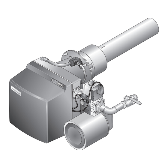
- Page 1 Installation and operating instruction Gas burner WG40…/3-A ZM-PLN 83322002 1/2022-10...
-
Page 2: Table Of Contents
Installation and operating instruction Gas burner WG40…/3-A ZM-PLN User instructions ...................... 5 1.1 Target group ........................ 5 1.2 Symbols .......................... 5 1.3 Guarantee and Liability .................... 6 Safety ............................. 7 2.1 Designated application .................... 7 2.2 When gas can be smelled .................. 7 2.3 ... - Page 3 Installation and operating instruction Gas burner WG40…/3-A ZM-PLN 6.2 Display .......................... 38 6.2.1 Info level ....................... 39 6.2.2 Service level ...................... 40 6.2.3 Parameter level .................... 41 6.2.4 Access level ...................... 43 6.3 Linearisation ........................ 44 Commissioning ......................
- Page 4 Installation and operating instruction Gas burner WG40…/3-A ZM-PLN Troubleshooting ...................... 98 10.1 Procedures for fault conditions ................ 98 10.1.1 Display off ...................... 98 10.1.2 Display OFF ...................... 99 10.1.3 Display flashes .................... 99 10.1.4 Detailed fault codes .................. 100 10.2 ...
-
Page 5: User Instructions
Installation and operating instruction Gas burner WG40…/3-A ZM-PLN 1 User instructions 1 User instructions This manual forms part of the equipment and must be kept on site. Translation of original Carefully read the manual prior to working on the unit. operating instructions 1.1 Target group The manual is intended for the operator and qualified personnel. -
Page 6: Guarantee And Liability
Weishaupt parts force majeure unauthorised modifications made to the unit the installation of additional components, which have not been tested with the... -
Page 7: Safety
Installation and operating instruction Gas burner WG40…/3-A ZM-PLN 2 Safety 2 Safety 2.1 Designated application The burner is suitable for operation on heat exchangers to EN 303 and EN 676. If the burner is not used on combustion chambers to EN 303 and EN 676, a safety assessment of combustion and flame stability during individual process conditions and of the shutdown limits of the combustion plant has to be carried out and docu- mented. -
Page 8: Electrical Work
Carry out soundness test after each service and fault rectification. 2.4 Alterations to the construction of the equipment All conversions require written approval from Max Weishaupt GmbH. No additional components may be fitted, which have not been tested for use with the equipment. -
Page 9: Product Description
Installation and operating instruction Gas burner WG40…/3-A ZM-PLN 3 Product description 3 Product description 3.1 Type key Example: WG40N/3-A ZM-PLN Type Series: Compact burner Fuel: Gas Size N: Natural Gas F: Liquid Petroleum Gas Ratings size Construction Version Type of control: modulating Mixing head: Premix LowNO 9-136 83322002 1/2022-10 Luw... -
Page 10: Type And Serial Number
Gas burner WG40…/3-A ZM-PLN 3 Product description 3.2 Type and serial number The type and serial number on the type plate clearly identify the product. They are required by Weishaupt's customer service department. 1 Name plate Type: Ser. No.: 10-136... -
Page 11: Function
Installation and operating instruction Gas burner WG40…/3-A ZM-PLN 3 Product description 3.3 Function 3.3.1 Air supply Air damper The air damper regulates the air quantity required for combustion. The combustion manager drives the air damper via actuator. At burner shutdown the air damper closes automatically. -
Page 12: Gas Supply
Installation and operating instruction Gas burner WG40…/3-A ZM-PLN 3 Product description 3.3.2 Gas supply Gas isolating valve 1 The gas isolating valve opens and shuts off the gas supply. Multifunction assembly 8 The multifunction assembly contains: Gas filter Double gas valve Pressure regulators Gas filter 2 The gas filter protects the subsequent valve train components from foreign... - Page 13 Installation and operating instruction Gas burner WG40…/3-A ZM-PLN 3 Product description High gas pressure switch 6 (optional) Depending on the burner application, optional equipment may be required for op- timum operation [ch. 12.2]. The high gas pressure switch monitors the setting pressure. If the setting pressure exceeds the value set, the combustion manager initiates a controlled shutdown.
-
Page 14: Electrical Components
Installation and operating instruction Gas burner WG40…/3-A ZM-PLN 3 Product description 3.3.3 Electrical components Combustion Manager The combustion manager W-FM is the control unit of the burner. It controls the sequence of operation and monitors the flame. Operating panel The values and parameters of the combustion manager can be displayed and changed at the operating panel. -
Page 15: Inputs And Outputs
Gas butterfly valve actuator Slot analogue module EM3/3 or Fieldbus module EM3/2 W-FM cover External valve LPG Frequency converter for continuous running fan -weishaupt- Frequency converter Ignition unit Multifunction assembly or double gas valve Not used Bridging plug No. 7... -
Page 16: Program Sequence
Installation and operating instruction Gas burner WG40…/3-A ZM-PLN 3 Product description 3.3.5 Program sequence The operating phases for commissioning the burner are shown on the display. Phase Function After the power supply has been switched on the combustion manager performs a self-test. TEST At heat demand, the actuators for the air damper and the gas butterfly valve drive to the reference point. - Page 17 Installation and operating instruction Gas burner WG40…/3-A ZM-PLN 3 Product description W-FM 25 T1 T2 1234 1234 Ionisation electrode CLOSED position Flame sensor Ignition position Air pressure switch Partial load Air pressure switch for intake air filter Full load Temperature or pressure regulator Operating phase Temperature or pressure regulator full load Initialisation time (Test): 3 s...
-
Page 18: Technical Data
Temperature during transport/storage –20 … +70 °C relative humidity max 80 %, no dew point Installation elevation max 2000 m Consultation with Weishaupt is required for higher installation elevation. 3.4.4 Fuels Natural Gas E/LL Liquid Petroleum Gas B/P 18-136 83322002 1/2022-10 Luw... -
Page 19: Emissions
Fuel combustion air (temperature and humidity) medium temperature content in the flue gas Combustion chamber dimensions, see Weishaupt Partner Portal / Documents and Applications / Online Applications / NO calculation for burners. Sound levels Dyad noise emission values Measured sound power level L... - Page 20 Installation and operating instruction Gas burner WG40…/3-A ZM-PLN 3 Product description 3.4.6 Rating Combustion heat rating Natural Gas 60 … 700 kW 70 … 700 kW Capacity graph Capacity graph to EN 676. The capacity data given relates to an installation elevation of 0 m above sea level. For installation elevations above 0 m a capacity reduction of approx. 1 % per 100 m applies.
-
Page 21: Dimensions
Installation and operating instruction Gas burner WG40…/3-A ZM-PLN 3 Product description 3.4.7 Dimensions Burner ½ 60 mm 450 mm 235 mm 524 mm 577 mm 834 mm 213 mm 3.4.8 Weight approx. 37 kg 21-136 83322002 1/2022-10 Luw... -
Page 22: Installation
Installation and operating instruction Gas burner WG40…/3-A ZM-PLN 4 Installation 4 Installation 4.1 Installation requirements Burner type and capacity graph Burner and heat exchanger must be matched. Check burner type and burner capacity. Installation location Prior to installation ensure that: sufficient space is available for normal and service position [ch. 3.4.7] sufficient combustion air is available, if necessary install ducted air intake Prepare heat exchanger... - Page 23 Installation and operating instruction Gas burner WG40…/3-A ZM-PLN 4 Installation Only valid in Switzerland When installing and operating the regulations of SVGW, VKF, local and Cantonal regulations and the EKAS guideline (LPG Guideline Part 2) must be observed. The burner in its standard version is designed for valve train connection from the right.
- Page 24 Installation and operating instruction Gas burner WG40…/3-A ZM-PLN 4 Installation Installing the burner tube Pay attention not to damage the burner tube mat when removing and refitting the burner tube. Carefully lift burner tube 4 and push into the burner flange up to the stop, en- suring that: the longitudinal weld seam of the burner tube mat is not in the area of the igni- tion unit...
- Page 25 Installation and operating instruction Gas burner WG40…/3-A ZM-PLN 4 Installation Burner installation Place the burner on to the stud screws 6 and mount to the burner flange using nuts 7. Mount cooling air line 4 at screwed union 5. Remove eye bolts 3. Mount intermediate flange covers 1 with countersunk head screws 2. Plug the ignition cable into the ignition unit.
-
Page 26: Rotate Burner By 180° (Optional)
Installation and operating instruction Gas burner WG40…/3-A ZM-PLN 4 Installation 4.2.1 Rotate burner by 180° (optional) Fit burner flange Screw studs 4 to boiler plate. Rotate burner flange with insulator 2 180° and place onto stud screws with flange gasket 3. Mount burner flange to boiler plate using nuts 1. The aperture between insulator and refractory should be filled with flame-proof, resilient insulating material. - Page 27 Installation and operating instruction Gas burner WG40…/3-A ZM-PLN 4 Installation Burner installation Mount operating panel 1 on the opposite side of the housing. Mount fixing bracket 2 on the opposite side of the housing. If necessary, rotate air filter box by 180° [ch. 4.2.2]. Rotate burner by 180°...
-
Page 28: Rotate Air Filter Box By 180° (Optional)
Installation and operating instruction Gas burner WG40…/3-A ZM-PLN 4 Installation 4.2.2 Rotate air filter box by 180° (optional) Detach the hose from the air pressure switch for the intake air filter on the im- pulse line. Remove intake air filter [ch. 9.10]. Remove screws 1 and completely remove intake cover. - Page 29 Installation and operating instruction Gas burner WG40…/3-A ZM-PLN 4 Installation Rotate intake cover 3 by 180° and mount using screws 1, ensuring correct alignment of the seal 2. Fit air filter. Fit the hose to the air pressure switch for the intake air filter on the impulse line. 29-136 83322002 1/2022-10 Luw...
-
Page 30: Installation
Installation and operating instruction Gas burner WG40…/3-A ZM-PLN 5 Installation 5 Installation 5.1 Gas supply Risk of explosion due to leaking gas Gas leaks can lead to a build-up of explosive gas/air mixture. With an ignition source present this can result in an explosion. Install gas supply with care. -
Page 31: Installing The Gas Valve Train
Installation and operating instruction Gas burner WG40…/3-A ZM-PLN 5 Installation 5.1.1 Installing the gas valve train Only in conjunction with W-MF and gas connection pressure > 150 mbar If the gas connection pressure is > 150 mbar, a pressure regulator has to be fitted upstream of the W-MF. - Page 32 Installation and operating instruction Gas burner WG40…/3-A ZM-PLN 5 Installation Installing the gas valve train from the left To fit the gas valve train to the burner from the left, the burner has to be installed rotated by 180°. To do this, additional conversion measures are required. Move the gas pressure switch prior to installing the multifunction assembly: Remove closing plug 1 and gas pressure switch 3.
- Page 33 Installation and operating instruction Gas burner WG40…/3-A ZM-PLN 5 Installation Accessories ¾'' ... 1½'' 1 Low gas pressure switch with mechanical interlock (B34) 2 High gas pressure switch (B33) 33-136 83322002 1/2022-10 Luw...
-
Page 34: Carry Out Soundness Test Of Gas Supply Line And Vent
Installation and operating instruction Gas burner WG40…/3-A ZM-PLN 5 Installation 5.1.2 Carry out soundness test of gas supply line and vent Only the gas supply company or a contract installation company may carry out a soundness test and vent the gas line. 34-136 83322002 1/2022-10 Luw... -
Page 35: Electrical Connection
Installation and operating instruction Gas burner WG40…/3-A ZM-PLN 5 Installation 5.2 Electrical connection Risk of electric shock Working on the device when voltage is applied can lead to electric shock. Isolate the device from the power supply prior to starting any work. DANGER Safeguard against accidental restart. -
Page 36: Operation
Installation and operating instruction Gas burner WG40…/3-A ZM-PLN 6 Operation 6 Operation 6.1 Operating panel [G] Gas Select gas butterfly valve actuator [–] Change values [L/A] Air Select air damper actuator [Enter] Reset burner Call up information: press for approx. 0.5 seconds: Info level press for approx. - Page 37 Installation and operating instruction Gas burner WG40…/3-A ZM-PLN 6 Operation Flame Signal The flame signal can be displayed during commissioning (setting level) by using a combination of keys. Press [Enter], [L/A] and [G] keys simultaneously. The flame signal is displayed. Recommended flame signal, see Service level information 19 [ch. 6.2.2].
-
Page 38: Display
Installation and operating instruction Gas burner WG40…/3-A ZM-PLN 6 Operation 6.2 Display The display shows the current operating status and operating data. 1 Setting level activated 2 Start phase activated 3 Info level activated 4 Actuator runs CLOSED 5 Actuator runs OPEN 6 Burner in operation 7 Lockout 8 Service level activated... -
Page 39: Info Level
Installation and operating instruction Gas burner WG40…/3-A ZM-PLN 6 Operation 6.2.1 Info level Burner data can be interrogated in the Info level . Press [Enter] for approx. 0.5 seconds. The Info level is activated. Press [Enter] to reach the next information. l,m³... -
Page 40: Service Level
Installation and operating instruction Gas burner WG40…/3-A ZM-PLN 6 Operation 6.2.2 Service level The service level provides information about: actuator position of the individual operating points the most recent fault flame signal during burner operation Press [Enter] for approx. 2 seconds. The service level is activated. -
Page 41: Parameter Level
Installation and operating instruction Gas burner WG40…/3-A ZM-PLN 6 Operation 6.2.3 Parameter level The parameter level can only be called up in Standby (OFF) mode. Press [+] and [Enter] keys simultaneously for approx. 2 seconds. The parameter level is activated. Press [+] key. - Page 42 Installation and operating instruction Gas burner WG40…/3-A ZM-PLN 6 Operation Pno. Parameters Setting range Factory setting Operating mode output X3:1 0: not activated 1: with pilot valve not interrupted 2: with pilot valve interrupted 3: Standard (external LPG valve) Flame sensor 0: ionisation electrode or flame sensor FLW 1: switch input (X3:14) 2: flame sensor QRB4 or flame sensor for continuous oper-...
-
Page 43: Access Level
Installation and operating instruction Gas burner WG40…/3-A ZM-PLN 6 Operation 6.2.4 Access level The configuration can be adapted relative to the burner type and/or version in the access level. In the parameter level, the display mode must be configured to 1, to enable access to parameters E0 … E3 [ch. 6.2.3]. -
Page 44: Linearisation
Installation and operating instruction Gas burner WG40…/3-A ZM-PLN 6 Operation 6.3 Linearisation During commissioning it is possible to carry out linearisation of the operating points in gas operation. During linearisation a straight line is generated from the operating point displayed to P9. -
Page 45: Commissioning
Installation and operating instruction Gas burner WG40…/3-A ZM-PLN 7 Commissioning 7 Commissioning 7.1 Prerequisite Commissioning must only be carried out by qualified personnel. Only correctly carried out commissioning ensures the operational safety. Do not operate the burner outside of the capacity graph [ch. 3.4.6]. Prior to commissioning ensure that: all assembly and installation work has been carried out correctly sufficient combustion air is available, if necessary install ducted air intake... -
Page 46: Connect Measuring Devices
Installation and operating instruction Gas burner WG40…/3-A ZM-PLN 7 Commissioning 7.1.1 Connect measuring devices Measuring device for ionisation current Remove ionisation cable from the plug coupling. Connect ammeter in series. Ionisation current Extraneous light detection from 1 μA Minimum ionisation current 5 μA Recommended ionisation current 9 … 15 μA... -
Page 47: Check Gas Connection Pressure
Installation and operating instruction Gas burner WG40…/3-A ZM-PLN 7 Commissioning 7.1.2 Check gas connection pressure Minimum connection pressure Add the combustion chamber pressure in mbar to the minimum connection pres- sure. The connection pressure should not fall below 15 mbar. Determine minimum connection pressure for low pressure installations from table [ch. 7.1.5]. -
Page 48: Check Soundness Of Gas Valve Train
Installation and operating instruction Gas burner WG40…/3-A ZM-PLN 7 Commissioning 7.1.3 Check soundness of gas valve train Carry out soundness test: prior to commissioning after all service and maintenance work First test phase Second and third test phase Test pressure 100 mbar ±10 % 100 mbar ±10 % Waiting time for pressure equal-... - Page 49 Installation and operating instruction Gas burner WG40…/3-A ZM-PLN 7 Commissioning ¾'' ...1½'' 1 First test phase 2 Second test phase 3 Third test phase 4 Blanking plate 49-136 83322002 1/2022-10 Luw...
- Page 50 Installation and operating instruction Gas burner WG40…/3-A ZM-PLN 7 Commissioning Fourth test phase In the fourth test phase, the joint to the mixture distributor 1 is tested for sound- ness. The test phase can only be carried out during or after burner commissioning. A leak detecting spray or electronic gas detector should be used for testing.
-
Page 51: Purging The Gas Valve Train
Installation and operating instruction Gas burner WG40…/3-A ZM-PLN 7 Commissioning 7.1.4 Purging the gas valve train Open test point into valve 1 [ch. 7.1.3]. Connect an approved vent hose to the test point. Vent hose must lead to atmosphere. Slowly open gas isolating valve. The gas/air mixture in the valve train vents via the hose to safe atmosphere. -
Page 52: Preset Pressure Regulator
Installation and operating instruction Gas burner WG40…/3-A ZM-PLN 7 Commissioning 7.1.5 Preset pressure regulator Determine setting pressure Add the combustion chamber pressure in mbar to the setting pressure into the gas butterfly valve. Determine setting pressure from the table and note down. 52-136 83322002 1/2022-10 Luw... - Page 53 Installation and operating instruction Gas burner WG40…/3-A ZM-PLN 7 Commissioning The details given for calorific value H relate to 0 °C and 1013 mbar. The table values have been calculated under ideal conditions. The values are there- fore guide values for basic settings. Full load Setting pressure Min.
- Page 54 Installation and operating instruction Gas burner WG40…/3-A ZM-PLN 7 Commissioning Preset setting pressure Only in conjunction with W-MF and gas connection pressure > 150 mbar The pre-pressure must be set to approx. 90 mbar. Set FRS pressure regulator, see additional sheet (print No. 835109xx). Preset setting pressure determined at multifunction assembly.
-
Page 55: Setting Values
Installation and operating instruction Gas burner WG40…/3-A ZM-PLN 7 Commissioning 7.1.6 Setting values Do not operate the burner outside of the capacity graph [ch. 3.4.6]. Set air damper setting and fan speed relative to the combustion heat rating re- quired. Determine air damper setting and fan speed required from the diagram and note down. -
Page 56: Preset Gas And Air Pressure Switch
Installation and operating instruction Gas burner WG40…/3-A ZM-PLN 7 Commissioning 7.1.7 Preset gas and air pressure switch The presetting of the pressure switches is only valid during commissioning. Once commissioning has been completed the pressure switches must be set correctly [ch. 7.4]. -
Page 57: Adjusting The Burner
Installation and operating instruction Gas burner WG40…/3-A ZM-PLN 7 Commissioning 7.2 Adjusting the burner Risk of electric shock Touching the ignition device can lead to electric shock. Do not touch ignition device during the ignition process. DANGER Check flame signal during commissioning [ch. 7.1.1]. 1. - Page 58 Installation and operating instruction Gas burner WG40…/3-A ZM-PLN 7 Commissioning Press and hold [L/A] key and set air damper setting determined using the [–] or [+] key [ch. 7.1.6]. Press and hold [G] key using [–] or [+] key set gas butterfly valve to the same value.
- Page 59 Installation and operating instruction Gas burner WG40…/3-A ZM-PLN 7 Commissioning 2. Check sequence of operation Open gas isolating valve. Pressure in gas valve train increases. Close isolating valve. Plug in bridging plug No. 7 on combustion manager. Burner starts. Valve proving is carried out. Speed standardisation is started.
- Page 60 Installation and operating instruction Gas burner WG40…/3-A ZM-PLN 7 Commissioning 3. Preset setting pressure If a controlled shutdown or lockout occurs during setting: Briefly press [G] and [L/A] keys simultaneously. Press [+] key. Combustion manager changes to setting level. Open test point for setting pressure and connect pressure measuring device. Open gas isolating valve.
- Page 61 Installation and operating instruction Gas burner WG40…/3-A ZM-PLN 7 Commissioning 4. Drive to full load Press [+] key. Burner drives to operating point P1. Check CO content of combustion and if necessary adjust combustion values via gas butterfly valve setting [G]. Press [+] key.
- Page 62 Installation and operating instruction Gas burner WG40…/3-A ZM-PLN 7 Commissioning 6. Adjusting operating point P1 Press [-] key. P9 is saved. Burner drives to operating point P8. Check CO content of combustion and if necessary adjust combustion values via gas butterfly valve setting [G]. Press [-] key.
- Page 63 Installation and operating instruction Gas burner WG40…/3-A ZM-PLN 7 Commissioning 8. Perform linearisation [ch. 6.3] Press [+] key. Burner drives to operating point P1. Press [Enter]. Combustion manager changes to linearisation mode. Confirm with [+] key. Linearisation is initiated. The display then shows operating point P1. Calculation from P1 to P9 was carried out.
- Page 64 Installation and operating instruction Gas burner WG40…/3-A ZM-PLN 7 Commissioning 10. Adjust partial load Press [G] and [L/A] keys simultaneously. Burner drives to partial load. The lower operating limit is displayed (bu). Define partial load whilst observing: data supplied by boiler manufacturer burner capacity graph [ch. 3.4.6] Determine gas throughput, if necessary adjust partial load (bu) using [+] key.
-
Page 65: Check Soundness Of Burner Flange
Installation and operating instruction Gas burner WG40…/3-A ZM-PLN 7 Commissioning 7.3 Check soundness of burner flange Use foaming agents, a leak detection spray or an electronic gas detector to check for leaks. Start burner and drive to full load. Check all components and transitions 1 on the burner flange. If necessary, tighten screws, nuts and components. -
Page 66: Set Pressure Switches
Installation and operating instruction Gas burner WG40…/3-A ZM-PLN 7 Commissioning 7.4 Set pressure switches 7.4.1 Set gas pressure switch Low gas pressure switch/valve proving gas pressure switch The switch point must be checked and if necessary adjusted during commission- ing. Connect pressure measuring device to test point 1 of the low gas pressure switch. -
Page 67: Set Fan Air Pressure Switch
Installation and operating instruction Gas burner WG40…/3-A ZM-PLN 7 Commissioning 7.4.2 Set fan air pressure switch The switch point must be checked and if necessary adjusted during commission- ing. Connect pressure measuring device for differential pressure measurement. Start the burner. Carry out differential pressure measurement across the whole capacity range of the burner and determine the lowest differential pressure. -
Page 68: Set Intake Air Filter Air Pressure Switch
Installation and operating instruction Gas burner WG40…/3-A ZM-PLN 7 Commissioning 7.4.3 Set intake air filter air pressure switch Check factory presetting of air pressure switch 1 if necessary adjust: –2 mbar (LGW 3) 68-136 83322002 1/2022-10 Luw... -
Page 69: Concluding Work
Installation and operating instruction Gas burner WG40…/3-A ZM-PLN 7 Commissioning 7.5 Concluding work Check control and safety devices. Remove gas pressure measuring devices and close all test points. Conclude valve proving of gas valve train (fourth test phase) [ch. 7.1.3]. Enter combustion values and settings in the commissioning record and/or test sheet. - Page 70 Installation and operating instruction Gas burner WG40…/3-A ZM-PLN 7 Commissioning 7.6 Check combustion Determine excess air Set O content relative to NO requirement [ch. 3.4.6]. Measure and document O content. Check flue gas temperature Check flue gas temperature. Ensure that the flue gas temperature complies with the data provided by the boiler manufacturer.
-
Page 71: Calculate Gas Throughput
Installation and operating instruction Gas burner WG40…/3-A ZM-PLN 7 Commissioning 7.7 Calculate gas throughput Formula symbol Description Example values Operating volume [m – Volume measured at gas meter at current pressure and temperature (gas throughput). Standard volume [m – Volume gained by gas at 1013 mbar and 0 C. Conversion factor –... -
Page 72: Subsequent Optimisation Of Operating Points
Installation and operating instruction Gas burner WG40…/3-A ZM-PLN 7 Commissioning 7.8 Subsequent optimisation of operating points If necessary, the combustion values can subsequently be corrected. Unplug bridging plug No. 7 on combustion manager. Combustion manager drives to Standby. Briefly press [–] and [+] simultaneously. Combustion manager changes to access level. -
Page 73: Shutdown
Installation and operating instruction Gas burner WG40…/3-A ZM-PLN 8 Shutdown 8 Shutdown In the event of operational failure: Switch off burner. Close fuel shut off devices. 73-136 83322002 1/2022-10 Luw... -
Page 74: Servicing
The design lifespan of the components is listed in the service plan [ch. 9.2]. Weishaupt recommends a service contract is entered into to ensure regular in- spections. - Page 75 Installation and operating instruction Gas burner WG40…/3-A ZM-PLN 9 Servicing Prior to every servicing Inform the operator about the extent of service work to be carried out. Switch off mains switch of installation and safeguard against accidental reactiva- tion. Close fuel shut off devices. Remove cover.
-
Page 76: Service Plan
Installation and operating instruction Gas burner WG40…/3-A ZM-PLN 9 Servicing 9.2 Service plan Components Criteria / design lifespan Service procedure Ionisation and ignition electrode Soiling Clean Damage / wear Replace [ch. 9.9] Recommendation: at least every 2 years Ionisation and ignition cable Damage Replace Burner tube surface... -
Page 77: Removing And Refitting Mixture Distributor
Installation and operating instruction Gas burner WG40…/3-A ZM-PLN 9 Servicing 9.3 Removing and refitting mixture distributor Observe notes on servicing [ch. 9.1]. Risk of explosion due to leaking gas It is possible for gas to leak out if the gasket 5 is seated incorrectly. Following work on the mixture distributor, ensure the gasket is clean and seated DANGER correctly, if necessary replace. -
Page 78: Set Mixture Distributor
Installation and operating instruction Gas burner WG40…/3-A ZM-PLN 9 Servicing 9.4 Set mixture distributor Observe notes on servicing [ch. 9.1]. The distance between mixture distributor and front edge of intermediate flange can not be measured with the burner mounted. This is only possible indirectly with the mixture distributor removed, with dimension Lx. -
Page 79: Service Position
Installation and operating instruction Gas burner WG40…/3-A ZM-PLN 9 Servicing 9.5 Service position Observe notes on servicing [ch. 9.1]. The burner mounted rotated by 180° cannot be placed into the service position. Remove mixture distributor [ch. 9.3]. Unplug plug 3 from ignition unit. Remove cover 2 and remove plugs. -
Page 80: Removing And Refitting Fan Wheel
Installation and operating instruction Gas burner WG40…/3-A ZM-PLN 9 Servicing 9.6 Removing and refitting fan wheel Observe notes on servicing [ch. 9.1]. Removing Place housing cover into service position [ch. 9.5]. Remove grub screw 1 and remove fan wheel. Refitting Refit fan wheel in reverse order and ensure correct alignment of the spring washer 2 screw in new grub screw 1 turn fan wheel to ensure it moves freely... -
Page 81: Replace Variable Speed Drive Sensor
Installation and operating instruction Gas burner WG40…/3-A ZM-PLN 9 Servicing 9.7 Replace variable speed drive sensor Observe notes on servicing [ch. 9.1]. Removing Remove fan wheel [ch. 9.6]. Undo locknut 3. Remove variable speed drive sensor 2. Refitting Refit new VSD sensor in reverse order, whilst ensuring the the VSD sensor is flush with the motor flange 1 (dimension X = 0 mm). -
Page 82: Remove Burner Motor
Installation and operating instruction Gas burner WG40…/3-A ZM-PLN 9 Servicing 9.8 Remove burner motor Observe notes on servicing [ch. 9.1]. Remove air pressure switch for intake air filter. Remove fan wheel [ch. 9.6]. Unplug plug 1. Hold motor and remove screws 2. Remove motor. -
Page 83: Set Ionisation And Ignition Electrodes
Installation and operating instruction Gas burner WG40…/3-A ZM-PLN 9 Servicing 9.9 Set ionisation and ignition electrodes Observe notes on servicing [ch. 9.1]. Danger of getting burned on hot components Hot components can lead to burns. Allow components to cool. WARNING Remove protective housing 1. Remove ionisation cable and ignition cable 2. -
Page 84: Removing Intake Air Filter
Installation and operating instruction Gas burner WG40…/3-A ZM-PLN 9 Servicing 9.10 Removing intake air filter Observe notes on servicing [ch. 9.1]. Remove pre-filter 3 Remove screws 4 for intake air filter. Remove intake air filter 2. Clean filter Clean pre-filter 3, replace if heavily soiled. Blow through intake air filter 2 from inside to the outside. -
Page 85: Removing And Refitting Air Damper Actuator
Installation and operating instruction Gas burner WG40…/3-A ZM-PLN 9 Servicing 9.11 Removing and refitting air damper actuator Observe notes on servicing [ch. 9.1]. Removing Remove actuator plug 4 from combustion manager. Remove screws 5. Remove actuator with fixing plate 3 and shaft 2. Refitting Damage to the actuator caused by turning the hub Actuator could be damaged. -
Page 86: Removing And Refitting Angle Drive
Installation and operating instruction Gas burner WG40…/3-A ZM-PLN 9 Servicing 9.12 Removing and refitting angle drive Observe notes on servicing [ch. 9.1]. Removing Remove air damper actuator [ch. 9.11]. Remove screws 2. Remove angle drive. Refitting Turn shaft 1 to its stop (air damper Open) and hold. Fit angle drive to shaft. -
Page 87: Removing And Refitting Gas Butterfly Valve Actuator
Installation and operating instruction Gas burner WG40…/3-A ZM-PLN 9 Servicing 9.13 Removing and refitting gas butterfly valve actuator Observe notes on servicing [ch. 9.1]. Removing Remove actuator plug 1 from combustion manager. Remove screws 2. Remove actuator. Refitting Damage to the actuator caused by turning the hub Actuator could be damaged. -
Page 88: Removing And Refitting Burner Tube
Installation and operating instruction Gas burner WG40…/3-A ZM-PLN 9 Servicing 9.14 Removing and refitting burner tube Observe notes on servicing [ch. 9.1]. Removing Pay attention not to damage the burner tube mat when removing and refitting the burner tube. Disconnect gas valve train. Remove intermediate flange covers 1. - Page 89 Installation and operating instruction Gas burner WG40…/3-A ZM-PLN 9 Servicing Remove ignition unit 2. Remove screws 3. Carefully pull out burner tube 1, ensuring that the burner tube mat is not dam- aged. Cleaning the burner tube Check soiling of burner tube mat by holding a lamp into the burner tube. If soiled, clean the inside of the burner tube with a vacuum cleaner and a nylon brush - or -...
-
Page 90: Replacing Double Gas Valve Coil
Installation and operating instruction Gas burner WG40…/3-A ZM-PLN 9 Servicing 9.15 Replacing double gas valve coil Observe notes on servicing [ch. 9.1]. Ensure correct voltage and solenoid number when replacing the solenoid coil. Undo screw(s) 1. Remove cap 2. With DMV also remove metal plate 4. Replace solenoid coil 3. -
Page 91: Replace Breather Plug Of Multifunction Assembly
Installation and operating instruction Gas burner WG40…/3-A ZM-PLN 9 Servicing 9.16 Replace breather plug of multifunction assembly Observe notes on servicing [ch. 9.1]. A breather plug with integrated filter is fitted to protect the breather orifice against soiling. Replace breather plug 1. 91-136 83322002 1/2022-10 Luw... -
Page 92: Removing And Refitting Filter Insert Of Multifunction Assembly
Installation and operating instruction Gas burner WG40…/3-A ZM-PLN 9 Servicing 9.17 Removing and refitting filter insert of multifunction assembly Observe notes on servicing [ch. 9.1]. Ensure no dirt enters the multifunction assembly when removing and replacing the filter insert. Removing Remove screws 4. Remove cover 3. -
Page 93: Removing And Refitting Filter Insert In Gas Filter
Installation and operating instruction Gas burner WG40…/3-A ZM-PLN 9 Servicing 9.18 Removing and refitting filter insert in gas filter Observe notes on servicing [ch. 9.1]. Ensure no dirt enters the multifunction assembly when removing and replacing the filter insert. Removing Remove screws 1. Remove cover 2. -
Page 94: Replacing The Combustion Manager
Installation and operating instruction Gas burner WG40…/3-A ZM-PLN 9 Servicing 9.19 Replacing the combustion manager Observe notes on servicing [ch. 9.1]. Unplug all plugs. Undo screws 1. Push combustion manager upwards and replace. Connect all plugs again. Preset combustion manager Unplug bridging plug No. 7 on combustion manager. Switch on voltage supply. - Page 95 Installation and operating instruction Gas burner WG40…/3-A ZM-PLN 9 Servicing Press [G] and [L/A] simultaneously. Combustion manager changes to access level. Press [+]. Setting level (parameter E0) is displayed. Adopt value 0 (single fuel burner), if necessary adjust using [ENTER] and [-] key. Press [+].
- Page 96 Installation and operating instruction Gas burner WG40…/3-A ZM-PLN 9 Servicing Determine the operating points from the sticker 1. Set the burner using these operating points and adjust [ch. 7.2]. Brennereinstellung Datum: Stauscheiben- einstellung: Gaseinstelldruck bei Großlast: mbar Einstellungen am Feuerungsmanager: Voreinstellung Luftklappe bei Großlast (P9): °...
-
Page 97: Replacing The Fuse
Installation and operating instruction Gas burner WG40…/3-A ZM-PLN 9 Servicing 9.20 Replacing the fuse Observe notes on servicing [ch. 9.1]. Unplug connection plug from combustion manager. replace fuse (T6.3H, IEC 127-2/5). 1 Replacement fuse 97-136 83322002 1/2022-10 Luw... -
Page 98: Troubleshooting
Low water safety interlock on heat ex- Top up water. changer has triggered Reset low water safety interlock on heat exchanger. Notify your heating contractor or Weishaupt Customer Service if the problem occurs repeatedly. 98-136 83322002 1/2022-10 Luw... -
Page 99: Display Flashes
Installation and operating instruction Gas burner WG40…/3-A ZM-PLN 10 Troubleshooting 10.1.2 Display OFF The following faults may be corrected by the operator: Fault Cause Rectification Brenner not operating Temperature regulator or pressure regu- Adjust temperature regulator or pres- lator on heat exchanger has been set in- sure regulator on heat exchanger. -
Page 100: Detailed Fault Codes
Installation and operating instruction Gas burner WG40…/3-A ZM-PLN 10 Troubleshooting 10.1.4 Detailed fault codes Additional information, which breaks down the error in more detail, can be dis- played by pressing a button. The first detailed fault code and the second detailed fault code are only relevant for the following faults: 1. - Page 101 Installation and operating instruction Gas burner WG40…/3-A ZM-PLN 10 Troubleshooting 10.2 Rectifying faults Faults must only be rectified by qualified personnel: Fault codes Cause Rectification 01h … 02h Internal unit fault Interrupt the voltage supply temporarily Reset the burner, if fault reoccurs replace the 05h …...
- Page 102 Installation and operating instruction Gas burner WG40…/3-A ZM-PLN 10 Troubleshooting Faults must only be rectified by qualified personnel: Fault codes Cause Rectification Switch off via PC Software – Second detailed fault code: A1h Check Bus address Invalid Bus address Second detailed fault code: A5h Check configuration at output B4 Configuration at output B4 incorrect Second detailed fault code: A6h...
- Page 103 Installation and operating instruction Gas burner WG40…/3-A ZM-PLN 10 Troubleshooting Faults must only be rectified by qualified personnel: Fault codes Cause Rectification Plugs of actuators for gas and air mixed up Change over plugs Tolerance fault actuator Check freedom of movement of air damper and / or angle drive and gas butterfly valve Replace actuator Actuator does not drive to reference point cor-...
- Page 104 Installation and operating instruction Gas burner WG40…/3-A ZM-PLN 10 Troubleshooting Faults must only be rectified by qualified personnel: Fault codes Cause Rectification No flame signal after safety time Set ignition electrode [ch. 9.9] Check the ignition unit and replace if necessary Check solenoid valve coil and cable, replace if necessary Check the ionisation electrode and cable, re-...
-
Page 105: Operating Problems
Installation and operating instruction Gas burner WG40…/3-A ZM-PLN 10 Troubleshooting Faults must only be rectified by qualified personnel: Fault codes Cause Rectification Connection to actuator faulty Rectify the fault using the following procedure: Interrupt voltage supply Plug in plug on combustion manager correctly Fit W-FM cover [ch. 3.3.4]. -
Page 106: Technical Documentation
Installation and operating instruction Gas burner WG40…/3-A ZM-PLN 11 Technical documentation 11 Technical documentation 11.1 Program sequence The exact operating status of the combustion manager can also be displayed. Ac- tivate operating status [ch. 6]. Operating phase Operating status Condition / function Fault present F .. - Page 107 Installation and operating instruction Gas burner WG40…/3-A ZM-PLN 11 Technical documentation Operating phase Operating status Condition / function Restart interlock 16 ..Reference search actuator - air damper and gas butterfly valve Test gas butterfly valve actuator 105° Drive to Standby position Internal sequence Insufficient gas, low gas pressure switch (X3:14) OFFGd...
-
Page 108: Conversion Table Unit Of Pressure
5.1.2, table 5 are used to provide the evidence of service performance of the burner during type testing. As -weishaupt- gas and dual fuel burners fulfil this requirement completely, the ap- pliance category, as well as the test gases used with the permissible connection pressure range, are listed on the name plate when labelling the burner to point 6.2 . - Page 109 Installation and operating instruction Gas burner WG40…/3-A ZM-PLN 11 Technical documentation Alternative appliance category to I2R Country of destination Appliance category Test gas Connection pressure mbar AT (Austria) G 20 BE (Belgium) I2E+, I2N, I2E(S), I2E(R) G 20 Pressures 20 - 25 CH (Switzerland) G 20 CZ (Czech Republic)
- Page 110 Installation and operating instruction Gas burner WG40…/3-A ZM-PLN 11 Technical documentation Alternative appliance category to I3R Country of destination Appliance category Test gas Connection pressure mbar AT (Austria) I3B/P, I3P G 30 + G 31 30 / 50 BE (Belgium) I3+, I3P, I3B, I3B/P G 30 + G 31 Pressures...
- Page 111 Installation and operating instruction Gas burner WG40…/3-A ZM-PLN 11 Technical documentation Alternative appliance category to II2R/3R Country of destination Appliance category Test gas Connection pressure Test gas Connection pressure mbar mbar AT (Austria) II2H3B/P, II2H3P G 20 G 30 + G 31 30 / 50 BE (Belgium) II2E+3P, II2E+3+, II2E+3B, G 20...
-
Page 112: Project Planning
Installation and operating instruction Gas burner WG40…/3-A ZM-PLN 12 Project planning 12 Project planning 12.1 Continuous running fan or post-purge Fire hazard due to failure of the combustion air fan Failure of the combustion air fan (e.g. due to a power failure or defective motor) during operation with continuous running fan or increased post-purge may result in back radiation or hot flue gases flowing back into the burner housing. -
Page 113: Additional Requirements
Installation and operating instruction Gas burner WG40…/3-A ZM-PLN 12 Project planning 12.2 Additional requirements Additional requirements for burner for liquid and gaseous fuels in accordance with EN 676: the pressure equipment operates in accordance with the Pressure Equipment Directive 2014/68/EU as a component of an industrial thermo-processing system to EN 746-2 on steam and hot water water-tube boilers to EN 12952-8 2014/68/EU... -
Page 114: Spares
Installation and operating instruction Gas burner WG40…/3-A ZM-PLN 13 Spares 13 Spares 1.04 1.01 1.03 1.02 1.05 1.10 1.08 1.06 1.09 1.07 1.12 1.18 1.12 1.17 1.11 1.13 1.16 1.14 1.17 1.15 1.20 1.22 1.21 1.23 1.19 1.25 1.24 1.26 1.27 1.28 114-136... - Page 115 Installation and operating instruction Gas burner WG40…/3-A ZM-PLN 13 Spares Pos. Description Order No. 1.01 Cover 241 400 01 112 1.02 Screw M8 x 16 DIN 7991 404 412 1.03 Intermediate flange 232 400 01 257 – Stud screw DIN 939-M10 x 30 421 064 1.04 Intermediate flange cover.
- Page 116 Installation and operating instruction Gas burner WG40…/3-A ZM-PLN 13 Spares 2.17 2.16 2.18 2.15 2.13 2.19 2.23 2.11 2.21 2.20 2.25 2.28 2.24 2.14 2.29 2.04 2.27 2.03 2.10 2.34 2.26 2.02 2.33 2.22 2.05 2.11 2.30 2.31 2.35 2.32 2.01 2.02 2.22...
- Page 117 Installation and operating instruction Gas burner WG40…/3-A ZM-PLN 13 Spares Pos. Description Order No. 2.01 Motor 232 400 07 050 – Motor W-PM06/S-4 652 165 – Motor W-PM06/A-4 652 320 2.02 Screw ISO 4762 M8 x 16- 8.8 402 509 2.03 Shaft key 4 x 5 DIN 6888 490 154...
- Page 118 Installation and operating instruction Gas burner WG40…/3-A ZM-PLN 13 Spares 3.02 3.11 3.01 3.04 3.03 3.10 3.12 3.02 3.02 3.06 3.05 3.13 3.07 3.09 3.03 3.02 3.14 3.15 3.16 3.08 3.17 3.19 3.20 3.39 3.18 3.23 3.23 3.38 3.32 3.31 3.21 3.30 3.36...
- Page 119 Installation and operating instruction Gas burner WG40…/3-A ZM-PLN 13 Spares Pos. Description Order No. 3.01 Insulator – low temperature 232 400 01 042 – high temperature 232 400 01 052 3.02 Insulator fixing bracket – low temperature 232 400 01 327 –...
- Page 120 Installation and operating instruction Gas burner WG40…/3-A ZM-PLN 13 Spares 3.02 3.11 3.01 3.04 3.03 3.10 3.12 3.02 3.02 3.06 3.05 3.13 3.07 3.09 3.03 3.02 3.14 3.15 3.16 3.08 3.17 3.19 3.20 3.39 3.18 3.23 3.23 3.38 3.32 3.31 3.21 3.30 3.36...
- Page 121 Installation and operating instruction Gas burner WG40…/3-A ZM-PLN 13 Spares Pos. Description Order No. 3.17 Mixture distributor complete – Natural Gas 232 400 14 202 – Liquid Petroleum Gas 233 400 14 052 3.18 Lock housing complete 232 400 14 152 3.19 Mixture distributor –...
- Page 122 Installation and operating instruction Gas burner WG40…/3-A ZM-PLN 13 Spares 4.11 4.10 4.05 4.04 4.01 4.12 4.13 4.03 4.09 4.14 4.14 4.16 4.02 4.15 4.06 4.07 4.17 4.08 4.18 4.28 4.19 4.20 4.22 4.21 4.23 4.24 4.25 4.26 4.27 4.29 4.28 122-136 83322002 1/2022-10 Luw...
- Page 123 Installation and operating instruction Gas burner WG40…/3-A ZM-PLN 13 Spares Pos. Description Order No. 4.01 Comb. manager W-FM25 PO-O2 V 2.0 230V UNIT 600 496 4.02 Micro fuse T6.3H, IEC 127-2/5 483 011 22 457 4.03 Bracket for W-FM 232 400 12 017 4.04 Adapter D79.5 x 27 for bracket W-FM 232 400 12 027...
- Page 124 Installation and operating instruction Gas burner WG40…/3-A ZM-PLN 13 Spares 5.01 5.03 5.02 5.04 5.05 5.08 5.06 5.07 5.11 5.06 5.16 5.10 5.09 5.13 5.14 5.14 5.15 5.12 5.17* 5.18* 124-136 83322002 1/2022-10 Luw...
- Page 125 Installation and operating instruction Gas burner WG40…/3-A ZM-PLN 13 Spares Pos. Description Order No. 5.01 O ring 45 x 3 NBR 70, DIN 3771 445 518 5.02 Flange Rp1½ 232 400 26 027 5.03 Pressure test nipple G 453 001 5.04 Double nipple R1½...
- Page 126 Installation and operating instruction Gas burner WG40…/3-A ZM-PLN 13 Spares 5.01 5.03 5.02 5.04 5.05 5.08 5.06 5.07 5.11 5.06 5.16 5.10 5.09 5.13 5.14 5.14 5.15 5.12 5.17* 5.18* 126-136 83322002 1/2022-10 Luw...
- Page 127 Installation and operating instruction Gas burner WG40…/3-A ZM-PLN 13 Spares Pos. Description Order No. 5.16 Isolating valve with TAE – 998NG-¾-CE-TAS for Gas PN1 454 596 – 998NG-1-CE-TAS for Gas PN1 454 597 – 984 1½-CE-TAS MOP5 454 911 Isolating valve without TAE –...
- Page 128 Installation and operating instruction Gas burner WG40…/3-A ZM-PLN 13 Spares 6.01 6.04 6.03 6.07 6.05 6.06 6.15 6.08 6.09 6.02 6.11 6.10 6.12 6.09 6.14 6.13 6.18 6.22 6.08 6.19 6.20 6.17 6.08 6.21 6.16 6.24* 6.23* 128-136 83322002 1/2022-10 Luw...
- Page 129 Installation and operating instruction Gas burner WG40…/3-A ZM-PLN 13 Spares Pos. Description Order No. 6.01 O ring 45 x 3 NBR 70, DIN 3771 445 518 6.02 Valve train gr. press. reg. R2 DMV 525/12 232 400 26 252 6.03 Flange Rp1½...
-
Page 130: Notes
Installation and operating instruction Gas burner WG40…/3-A ZM-PLN 14 Notes 14 Notes 130-136 83322002 1/2022-10 Luw... - Page 131 Installation and operating instruction Gas burner WG40…/3-A ZM-PLN 14 Notes 131-136 83322002 1/2022-10 Luw...
-
Page 132: Key Word Index
Installation and operating instruction Gas burner WG40…/3-A ZM-PLN 15 Key word index 15 Key word index Electrical data .............. 18 Electrode................ 83 Access level .............. 37, 43 electrostatic discharge ............ 8 Actuator................. 85 Emission................ 19 Adjust.................. 72 Emission class .............. 19 Air damper .............. 11, 85 ESD protective measures ........... - Page 133 Installation and operating instruction Gas burner WG40…/3-A ZM-PLN 15 Key word index Ignition speed .............. 62 Pascal ................. 108 Ignition unit ................ 14 Personal protective equipment .......... 7 Indicating bolt .............. 78 Post purge air damper setting ......... 42 Info button................ 36 Post-purge time.............. 17 Info level ................ 39 PPE ..................
- Page 134 Installation and operating instruction Gas burner WG40…/3-A ZM-PLN 15 Key word index Unit .................. 108 Unit of pressure.............. 108 Valve proving.............. 12, 66 Valve train .............. 30, 31, 53 VisionBox ................ 37 Voltage supply .............. 18 VSD sensor .............. 81, 82 Weight................... 21 when gas can be smelled ...........
- Page 135 83322002 1/2022-10 Luw...
- Page 136 Max Weishaupt GmbH · 88475 Schwendi Weishaupt close by? Addresses, telephone numbers etc. can be found at www.weishaupt.de We reserve the right to make changes. All rights reserved. The complete program: Reliable technology and prompt, professional service W Burners up to 700 kW...
Need help?
Do you have a question about the WG40 /3-A ZM-PLN Series and is the answer not in the manual?
Questions and answers