Sign In
Upload
Manuals
Brands
Rohde & Schwarz Manuals
Inverter
SMCV100B
Rohde & Schwarz SMCV100B Manuals
Manuals and User Guides for Rohde & Schwarz SMCV100B. We have
5
Rohde & Schwarz SMCV100B manuals available for free PDF download: User Manual, Getting Started
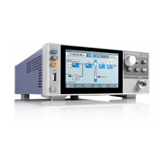
Rohde & Schwarz SMCV100B User Manual (853 pages)
Vector Signal Generator
Brand:
Rohde & Schwarz
| Category:
Inverter
| Size: 18 MB
Table of Contents
Table of Contents
3
Safety Instructions
15
Safety and Regulatory Information
15
Labels on R&S SMCV100B
17
Warning Messages in the Documentation
17
Korea Certification Class B
18
Welcome
19
Key Features
19
What's New
20
Documentation Overview
20
Getting Started Manual
20
User Manuals and Help
20
Data Sheets and Brochures
21
Release Notes and Open Source Acknowledgment (OSA)
21
Instrument Security Procedures
21
Printed Safety Instructions
21
Service Manual
21
Application Notes, Application Cards, White Papers, Etc
22
Getting Started
23
Preparing for Use
23
Lifting and Carrying
23
Unpacking and Checking
23
Choosing the Operating Site
23
Setting up the R&S SMCV100B
24
Considerations for Test Setup
25
Connecting to Power
26
Connecting to LAN
26
Connecting a Monitor
27
Connecting USB Devices
28
Connecting to RF 50 Ω
28
Connecting to Ref In/Ref out
29
Connecting to Dig. IQ HS X
30
Connecting to IP Data Interface
31
Switching on or off
32
Instrument Tour
33
Front Panel Tour
33
Rear Panel Tour
37
Trying out the Instrument
40
Generating an Unmodulated Carrier
41
Generating a Digitally Modulated Signal
42
Triggering the Instrument with an External Signal
45
Enabling and Configuring a Marker Signal
49
Verifying the Generated Signal with the Graphics Display
51
Saving and Recalling Settings
54
Generating a DAB Signal
56
System Overview
58
Brief Introduction to the Instrument's Concept
58
Signal Flow at a Glance
59
Internal Baseband Source ("Baseband" Block)
60
Digital Baseband Input/Output ("BB Input"/ "I/Q Digital" Block)
60
Additional White Gaussian Noise ("AWGN" Block)
61
I/Q Stream Mapper" Block
61
I/Q Modulator ("I/Q Mod" Block)
61
RF ("RF" Block)
61
Applications Examples of the R&S SMCV100B
61
Instrument Control
62
Means of Manual Interaction
62
Possible Ways to Operate the Instrument
62
Understanding the Display Information
63
Accessing the Functionality
68
Entering Data
69
Getting Information and Help
70
Remote Control
72
Remote Operation over VNC
72
Vnc
72
Configuring Internal Baseband Signals
73
Overview of the Signal Generation Modes
73
Accessing the Functions in the Baseband Domain
74
Generating Signals According to Broadcast Standards
75
Common Functions and Settings in the Baseband Domain
78
Basics on Signals, Modulation Types and Filters Used the Baseband Domain
78
Data, Clock and Control Signals and Sources in the Baseband
78
Regular Marker Output Signals
82
Baseband Trigger Signals
84
Supported Modulation Signals
92
Supported Coding Schemes
93
Supported Baseband Filters
94
Methods for Optimizing the Crest Factor
96
Common Settings
98
About the Custom Digital Modulation
104
Generating Custom Digital Modulated Signals
104
Required Options
104
Custom Digital Modulation Settings
105
General Settings
105
Settings
105
Data Source
108
Trigger, Marker and Clock Setting
108
Modulation Settings
110
Filter Settings
112
Power Ramp Control Settings
114
Data List Editor
116
Control and Marker Lists Editor
118
How to Create Data and Control Lists
122
References
125
Using the Arbitrary Waveform Generator (ARB)
135
About ARB
136
Required Options
136
ARB Settings
141
Settings
142
ARB General Settings
142
Sine Test Signals
146
Rectangular Test Signal
147
Constant IQ Test Signal
149
Trigger, Marker and Clock Settings
150
How to Create, Generate and Play Waveform Files
151
How to Work with Waveform Libraries
167
How to Stream Waveforms from an External Storage Device
170
Tags for Waveforms, Data and Control Lists
171
Usage
175
CLOCK: Frequency
175
CONTROL LENGTH: Controllength
176
EMPTYTAG-Length: #Emptysequence
177
LEVEL OFFS: Rmsoffset_Db,Peakoffset_Db
177
Marker Mode [#]: Generator
178
BURST LIST [#]: Pos0:State0; Pos1:State1
179
CW MODE LIST [#]: Pos0:State0; Pos1:State1
179
HOP LIST [#]: Pos0:State0; Pos1:State1
179
LEVATT LIST [#]: Pos0:State0; Pos1:State1
179
MAP LIST [#]: Pos0:State0; Pos1:State1
179
MARKER LIST [#]: Pos0:State0; Pos1:State1
179
SAMPLES: Samples
179
[TRACE] LIST [#]: Pos0:State0; Pos1:State1
179
WAVEFORM-Length: #I0Q0I1Q1
180
MWV_SEGMENT_COUNT: Numofseg
181
MWV_SEGMENT_CLOCK_MODE: Mode
182
MWV_SEGMENT_DURATION: Segdur0, Segdur1
182
MWV_SEGMENT_LENGTH: Samplesseg0, Samplesseg1
182
Mwv_Segment_Start
182
Samplestartoffsetseg0, Samplestartoffsetseg1
182
MWV_SEGMENT_CLOCK: Clockseg0, Clockseg1
183
MWV_SEGMENT_LEVEL_MODE: Mode
183
Filenameseg0.Wv", "Filenameseg1.Wv
184
Mwv_Segment_Files
184
Mwv_Segment_Level_Offs
184
MWV_SEGMENT_SETTINGS_FILE: Segsettingfilepath
184
Rmsoffs_Dbsg0,Peakoffs_Dbsg0
184
CONTROL LIST WIDTH4-Length: #M0M1
185
Mwv_Segmentx_Comment: Text
185
About the Multi-Segment Waveforms
189
Generating Multi-Segment Waveform Files
189
Reducing the Crest Factor
189
Required Options
189
Multi-Segment Settings
195
How to Create and Work with Multi-Segment Waveform Files
211
Reference to Triggering of Multi-Segment Waveforms
216
Generating Multi-Carrier Signals
219
About the Multi-Carrier Waveforms
220
Required Options
220
Multi-Carrier Settings
222
Settings: Set to Default
223
Mode
224
Number of Carriers
224
Save/Recall Frame
224
Carrier Spacing
225
Clipping
225
Crest Factor Mode
225
Filter Cutoff Frequency
225
Target Crest Factor
225
Power Reference
226
Signal Period
226
Signal Period Mode
226
Clock Rate
228
Create/Create and Load
228
File Size
228
Output File
228
Output Settings
228
Settings: Carrier State/Carrier Start/Start
232
Carrier Start/Start
232
Gain Start
232
Gain Step
232
Phase Start
232
Settings: Carrier State
232
Delay Start
233
Delay Step
233
Input Waveform File
233
Phase Step
233
Settings
233
How to Use the Multi-Carrier Function
234
Fm/Phim/Am Configuration and Settings
237
Generating Fm/Phim/Am/Pulse Modulation Signals
237
Pulse Modulation Configuration and Settings
241
About Baseband Offsets
244
Shifting and Boosting the Baseband Signal
244
Baseband Offsets Settings
246
How to Improve Signal Characteristics by Shifting the Baseband Signal
247
Configuring External Baseband Signals
249
Overview of the Input and Output Signals and Interfaces
249
Overview of the Baseband and RF Output Signals
250
Overview of the Baseband Signal Sources
250
Important Signal Parameters and Interface's Characteristics
251
Interdependencies
251
I/Q Stream Mapper Settings
254
System Configuration Settings
254
External RF and I/Q Settings
255
Settings
256
Auto Connect
257
Connect/Disconnect All Remote
257
Display
257
Connector Name
258
Direction
258
External Instrument
258
Preset Behavior: Keep Connections to External Instruments
258
I/Q Connection
259
Instrument Name
259
Remote Connection Status
259
Table of Contents
261
Clean Unused/Clean All
262
Detect/Scan
262
External Instrument
262
Device ID
263
Initialization Sequence
263
Remote Channel
263
RF Path
263
Set Symbolic Name
263
Apply and Connect
264
Remove Initialization Sequence
264
Overview
266
Digital Baseband Input Settings
267
General Settings
269
[:Source
270
Signal Input Settings
270
Peak Level
271
I/Q Digital Output Settings
272
General Settings
273
Channels Settings
274
Connected Device
274
IQ HS 1 Interface
274
Name and Serial Number of the Connected Instrument
274
None" Indicates that no Device Is Connected
274
Remote Command
274
The Transmitter Sample Rate, if Supported by the Transmitter
274
Remote Command
275
Signal Output Settings
276
Generating Time-Aligned Baseband Signals
278
Triggering Several Instruments with a Common Trigger Signal
278
About the AWGN Generator
280
Adding Noise to and Impairing the Signal
280
Adding Noise to the Signal
280
Required Options
280
AWGN Block
284
AWGN Settings
285
[:Source
287
Bit Rate
288
Reference Mode
288
Set Noise Power Via
288
Show Powers for Output
288
Carrier Power, Signal Power
289
Carrier/Noise Ratio, Signal/Noise Ratio
289
E B /N
289
Noise Power (System Bandwidth), Interferer Power
290
Noise Power (Total Bandwidth)
291
How to Configure the Noise Generator for Receiver Tests
292
About the Linear I/Q Impairments
294
Impairing the Signal
294
Required Options
294
Digital Impairments Settings
296
About the I/Q Modulator
298
Applying I/Q Vector Modulation
298
I/Q Modulator Settings
298
Required Options
298
Optimizing I/Q Modulation Performance
301
Configuring the RF Signal
302
How to Access the RF Settings
303
How to Activate the RF Signal Output
303
Required Options
303
How to Set the Frequency and Level
304
RF Frequency Settings
305
RF Level Settings
308
RF Phase Settings
311
Reference Frequency Settings
312
Reference Oscillator
312
Required Options
312
Reference Output Settings
315
Adjustment Settings
316
Varying the RF Signal in List or Sweep Mode
316
Signal Generation and Triggering in the Sweep and List Modes
318
About Sweep Mode
325
About List Mode
329
Significant Parameters and Functions
330
Sweep Mode Settings
332
State (Rf Frequency Sweep)
333
Current Frequency
334
Current Level
334
Mode
334
State (RF Level Sweep)
334
Retrace
335
Shape
335
Dwell Time
336
Spacing
336
Execute Single Sweep
337
Reset Sweep
337
Trigger Slope
337
Advertisement
Rohde & Schwarz SMCV100B User Manual (913 pages)
Vector Signal Generator
Brand:
Rohde & Schwarz
| Category:
Portable Generator
| Size: 21 MB
Table of Contents
Table of Contents
3
Safety Instructions
15
Safety and Regulatory Information
15
Labels on R&S SMCV100B
17
Warning Messages in the Documentation
18
Where to Find Key Documents on Rohde & Schwarz
18
Korea Certification Class B
18
Welcome
20
Key Features
20
Getting Started Manual
21
User Manuals and Help
21
Documentation Overview
21
What's New
21
Service Manual
22
Instrument Security Procedures
22
Printed Safety Instructions
22
Data Sheets and Brochures
22
Release Notes and Open Source Acknowledgment (OSA)
22
Application Notes, Application Cards, White Papers, Etc
23
Videos
23
Getting Started
24
Preparing for Use
24
Lifting and Carrying
24
Unpacking and Checking
24
Choosing the Operating Site
24
Setting up the R&S SMCV100B
25
Considerations for Test Setup
26
Connecting to Power
27
Connecting to LAN
27
Connecting a Monitor
28
Connecting USB Devices
29
Connecting to RF Coaxial Connectors
29
Connecting to RF 50 Ω
31
Connecting to Ref In/Ref out
31
Connecting to Dig. IQ HS X
31
Connecting to IP Data
32
Switching on or off
34
Front Panel Tour
35
Instrument Tour
35
Rear Panel Tour
39
Trying out the Instrument
42
Generating an Unmodulated Carrier
43
Generating a Digitally Modulated Signal
44
Triggering the Instrument with an External Signal
47
Enabling and Configuring a Marker Signal
51
Verifying the Generated Signal with the Graphics Display
53
Saving and Recalling Settings
56
Generating a DAB Signal
58
System Overview
60
Brief Introduction to the Instrument's Concept
60
Signal Flow at a Glance
61
Internal Baseband Source ("Baseband" Block)
62
Digital Baseband Input/Output ("BB Input"/ "I/Q Digital" Block)
62
Additional White Gaussian Noise ("AWGN" Block)
63
I/Q Stream Mapper" Block
63
I/Q Modulator ("I/Q Mod" Block)
63
RF ("RF" Block)
63
Applications Examples of the R&S SMCV100B
63
Instrument Control
64
Means of Manual Interaction
64
Possible Ways to Operate the Instrument
64
Understanding the Display Information
65
Accessing the Functionality
70
Entering Data
71
Getting Information and Help
72
Remote Control
74
Remote Operation over VNC
74
Vnc
74
Configuring Internal Baseband Signals
75
Overview of the Signal Generation Modes
75
Accessing the Functions in the Baseband Domain
76
Generating Signals According to Broadcast Standards
77
Basics on Signals, Modulation Types and Filters
80
Common Functions and Settings in the Baseband Domain
80
Common Settings
100
About the Custom Digital Modulation
106
Generating Custom Digital Modulated Signals
106
Required Options
106
Custom Digital Modulation Settings
107
General Settings
107
Settings
107
Data Source
110
Trigger, Marker and Clock Settings
110
Modulation Settings
112
Filter Settings
114
Power Ramp Control Settings
116
Data List Editor
118
Control and Marker Lists Editor
120
How to Create Data and Control Lists
124
References
127
Required Options
137
Using the Arbitrary Waveform Generator (ARB)
137
About ARB
138
ARB Settings
143
Settings: State
144
Load Waveform/File
145
Waveform Info
145
Clock Frequency
146
Create Multi Segment
146
HDD Streaming
146
Create Multi Carrier
147
Create Test Signal
147
Test Signal Form
147
How to Create, Generate and Play Waveform Files
152
How to Work with Waveform Libraries
168
How to Stream Waveforms from an External Storage Device
171
Tags for Waveforms, Data and Control Lists
173
Example: {Date: 2009-04-02;14:32:12}
176
CLOCK: Frequency
177
CONTROL LENGTH: Controllength
177
EMPTYTAG-Length: #Emptysequence
178
LEVEL OFFS: Rmsoffset_Db,Peakoffset_Db
179
Marker Mode [#]: Generator
180
SAMPLES: Samples
180
BURST LIST [#]: Pos0:State0; Pos1:State1
181
CW MODE LIST [#]: Pos0:State0; Pos1:State1
181
HOP LIST [#]: Pos0:State0; Pos1:State1
181
LEVATT LIST [#]: Pos0:State0; Pos1:State1
181
MAP LIST [#]: Pos0:State0; Pos1:State1
181
MARKER LIST [#]: Pos0:State0; Pos1:State1
181
[TRACE] LIST [#]: Pos0:State0; Pos1:State1
181
WAVEFORM-Length: #I0Q0I1Q1
182
MWV_SEGMENT_COUNT: Numofseg
183
MWV_SEGMENT_DURATION: Segdur0, Segdur1
183
MWV_SEGMENT_LENGTH: Samplesseg0, Samplesseg1
183
MWV_SEGMENT_CLOCK: Clockseg0, Clockseg1
184
MWV_SEGMENT_CLOCK_MODE: Mode
184
Mwv_Segment_Start
184
Samplestartoffsetseg0, Samplestartoffsetseg1
184
MWV_SEGMENT_LEVEL_MODE: Mode
185
Mwv_Segment_Level_Offs
185
Rmsoffs_Dbsg0,Peakoffs_Dbsg0
185
MWV_SEGMENT_SETTINGS_FILE: Segsettingfilepath
186
Generating Multi-Segment Waveform Files
190
Reducing the Crest Factor
190
About the Multi-Segment Waveforms
191
Required Options
191
Multi-Segment Settings
196
How to Create and Work with Multi-Segment Waveform Files
212
Reference to Triggering of Multi-Segment Waveforms
217
Generating Multi-Carrier Signals
220
About the Multi-Carrier Waveforms
221
Required Options
221
Multi-Carrier Settings
223
Section 6
224
Set to Default
224
Mode
225
Number of Carriers
225
Save/Recall Frame
225
Carrier Spacing
226
Clipping
226
Crest Factor Mode
226
Frequency
226
Target Crest Factor
226
Power Reference
227
Signal Period
227
Signal Period Mode
227
Clock Rate
229
Create/Create and Load
229
File Size
229
Output File
229
Output Settings
229
How to Use the Multi-Carrier Function
235
Fm/Phim/Am Configuration and Settings
238
Generating Fm/Phim/Am/Pulse Modulation Signals
238
Pulse Modulation Configuration and Settings
242
About Baseband Offsets
244
Shifting and Boosting the Baseband Signal
244
Baseband Offsets Settings
247
How to Improve Signal Characteristics by Shifting the Baseband Signal
248
Configuring External Baseband Signals
249
Overview of the Input and Output Signals and Interfaces
249
Overview of the Baseband and RF Output Signals
250
Overview of the Baseband Signal Sources
250
Important Signal Parameters and Interface's Characteristics
251
Interdependencies
251
I/Q Stream Mapper Settings
254
System Configuration Settings
254
External RF and I/Q Settings
255
Section 7
256
Auto Connect
257
Connect/Disconnect All Remote
257
Display
257
Connector Name
258
Direction
258
External Instrument
258
Preset Behavior: Keep Connections to External Instruments
258
I/Q Connection
259
Instrument Name
259
Remote Connection Status
259
Overview
266
Digital Baseband Input Settings
267
General Settings
269
Signal Input Settings
270
I/Q Digital Output Settings
272
General Settings
273
Channels Settings
275
Signal Output Settings
277
Generating Time-Aligned Baseband Signals
278
Triggering Several Instruments with a Common Trigger Signal
278
About the AWGN Generator
280
Adding Noise to and Impairing the Signal
280
Adding Noise to the Signal
280
Required Options
280
AWGN Block
284
AWGN Settings
285
Advertisement
Rohde & Schwarz SMCV100B Getting Started (79 pages)
Vector Signal Generator
Brand:
Rohde & Schwarz
| Category:
Inverter
| Size: 5 MB
Table of Contents
Table of Contents
3
1 Safety and Regulatory Information
7
Safety Instructions
7
Korea Certification Class B
10
2 Documentation Overview
11
Labels on R&S SMCV100B
10
Getting Started Manual
11
User Manuals and Help
11
Data Sheets and Brochures
12
Instrument Security Procedures
12
Printed Safety Instructions
12
Service Manual
12
Application Notes, Application Cards, White Papers, Etc
13
3 Key Features
14
Release Notes and Open Source Acknowledgment (OSA)
13
Choosing the Operating Site
15
Lifting and Carrying
15
4 Preparing for Use
15
Unpacking and Checking
15
Placing the R&S SMCV100B on a Bench Top
16
Setting up the R&S SMCV100B
16
Mounting the R&S SMCV100B in a Rack
17
Important Aspects for Test Setup
18
Connecting to Power
19
Connecting to LAN
19
Connecting Monitor
20
Connecting USB Devices
21
Connecting to Ref In/Ref out
22
Connecting to RF 50 Ω
22
Connecting to Dig. IQ HS X
23
Connecting to IP Data Interface
24
Switching on or off
25
Touchscreen
29
Keys
30
5 Instrument Tour
28
Front Panel Tour
28
Function Keys
30
On/Standby
30
Utility Keys
30
Editing Keys
31
Navigation Controls
31
Rotary Knob
31
Connectors
32
Rear Panel Tour
32
Connectors
33
Generating a DAB Signal
55
Brief Introduction to the Instrument's Concept
58
Signal Flow at a Glance
58
Digital Baseband Input/Output ("BB Input"/ "I/Q Digital" Block)
60
Internal Baseband Source ("Baseband" Block)
60
Additional White Gaussian Noise ("AWGN" Block)
61
I/Q Stream Mapper" Block
61
Applications Examples of the R&S SMCV100B
62
I/Q Modulator ("I/Q Mod" Block)
62
RF ("RF" Block)
62
Possible Ways to Operate the Instrument
63
Means of Manual Interaction
64
Understanding the Display Information
64
6 Trying out the Instrument
36
Generating an Unmodulated Carrier
37
Generating a Digitally Modulated Signal
39
Triggering the Instrument with an External Signal
41
Enabling and Configuring a Marker Signal
47
Verifying the Generated Signal with the Graphics Display
48
Saving and Recalling Settings
52
Status Bar
65
Block Diagram
66
Taskbar
67
Additional Display Characteristics
68
Accessing the Functionality
70
Entering Data
71
Entering Alphanumeric Parameters
72
Entering Numeric Parameters
72
Undo and Redo Actions
72
Getting Information and Help
72
Remote Control
74
Remote Operation over VNC
75
Rohde & Schwarz SMCV100B Getting Started (81 pages)
Vector Signal Generator
Brand:
Rohde & Schwarz
| Category:
Portable Generator
| Size: 5 MB
Table of Contents
Table of Contents
3
Safety and Regulatory Information
7
Safety Instructions
7
Labels on R&S SMCV100B
11
Warning Messages in the Documentation
11
Where to Find Key Documents on Rohde & Schwarz
12
Korea Certification Class B
12
Documentation Overview
13
Getting Started Manual
13
User Manuals and Help
13
Service Manual
14
Instrument Security Procedures
14
Printed Safety Instructions
14
Specifications and Product Brochures
14
Calibration Certificate
15
Release Notes and Open Source Acknowledgment
15
Application Notes, Application Cards, White Papers, Etc
15
Videos
15
Key Features
16
Preparing for Use
17
Lifting and Carrying
17
Unpacking and Checking
17
Choosing the Operating Site
17
Setting up the R&S SMCV100B
18
Considerations for Test Setup
20
Connecting to Power
21
Connecting to LAN
21
Connecting a Monitor
22
Connecting USB Devices
23
Connecting to RF Coaxial Connectors
24
Connecting to RF 50 Ω
25
Connecting to Ref In/Ref out
26
Connecting to Dig. IQ HS X
26
Connecting to IP Data
27
Switching on or off
29
Instrument Tour
31
Front Panel Tour
31
Rear Panel Tour
35
Trying out the Instrument
38
Generating an Unmodulated Carrier
39
Generating a Digitally Modulated Signal
41
Triggering the Instrument with an External Signal
43
Enabling and Configuring a Marker Signal
49
Verifying the Generated Signal
50
Saving and Recalling Settings
54
Generating a DAB Signal
57
System Overview
60
Brief Introduction to the Instrument's Concept
60
Signal Flow at a Glance
60
Internal Baseband Source ("Baseband" Block)
62
Advertisement
Related Products
Rohde & Schwarz R&S SMC-B103
Rohde & Schwarz R&S SMC-B101
Rohde & Schwarz SMB100A
Rohde & Schwarz SMF100A
Rohde & Schwarz SMF-B22
Rohde & Schwarz SMF-B82
Rohde & Schwarz SMF-B84
Rohde & Schwarz SMF-B122
Rohde & Schwarz SMF-B144N
Rohde & Schwarz SMF-K4
Rohde & Schwarz Categories
Measuring Instruments
Test Equipment
Portable Generator
Power Supply
Accessories
More Rohde & Schwarz Manuals
Login
Sign In
OR
Sign in with Facebook
Sign in with Google
Upload manual
Upload from disk
Upload from URL