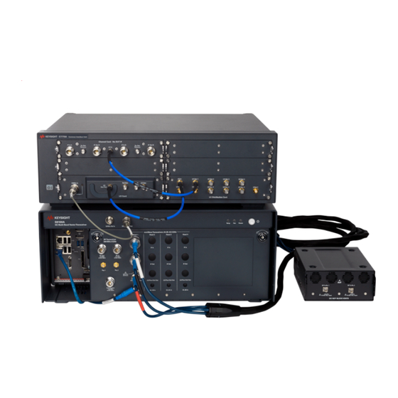
Keysight S9100A Startup Manual
5g multi-band vector transceiver
Hide thumbs
Also See for S9100A:
- Startup manual (90 pages) ,
- Installation manual (18 pages) ,
- User & programmers manual (3096 pages)
Table of Contents
Advertisement
Quick Links
Advertisement
Table of Contents

Related Manuals for Keysight S9100A


Summary of Contents for Keysight S9100A
- Page 1 Startup Guide S9100A 5G Multi-Band Vector Transceiver...
- Page 2 FAR LEVEL (COMBINATION OF CHASSIS, and the DFARS and are set forth © Keysight Technologies, Inc. 2019 – 2022 CONTROLLERS, MODULES, ETC.) specifically in writing elsewhere in the No part of this manual may be PERFORMANCE, SAFETY, OR EULA.
-
Page 3: Table Of Contents
3. 2. 3 Connectors, Head 1 on the Rugged Front Panel 3. 2. 4 Connectors, M9037A PXIe Embedded Controller 3. 2. 5 Connectors, S9100A Rear Panel (M9019A PXIe Chassis) 3. 2. 6 Connectors, E7770A Common Interface Unit (CIU) 3. 2. 6. 1 Connectors, E7770A CIU, Local Oscillator Card (LO Card) 3. - Page 4 6 Verify Operation 6. 1 Verifying X-Apps Software Controls the S9100A 6. 1. 1 Verify the X-Apps Software Controls the S9100A at 3 GHz 6. 1. 2 Verify the X-Apps Software Controls the S9100A at 28 GHz 7 Run Calibrations 7.
- Page 5 8. 0. 4 Display Subsystem 8. 0. 5 Service Subsystem 8. 0. 6 Reference Oscillator Subsystem 8. 0. 7 Chassis Subsystem 8. 0. 8 Source Subsystem 8. 0. 8. 1 Example of Controlling the Secondary Transceiver Source...
-
Page 7: Overview
5G New Radio (5G NR) infrastructure equipment in both the FR1 (380 MHz to 6 GHz) and millimeter wave FR2 (24.25 to 43.5 GHz) frequencies. In this document... This document describes the installation process to start up and prepare the Keysight S9100A 5G Multi-Band Vector Transceiver for use. 1. Review this Overview Review Safety Requirements on page 3 Review Hardware Components on page 19 Install Hardware on page 37... - Page 8 S9100A 5G Multi-Band Vector Transceiver, Startup Guide...
-
Page 9: Review Safety Requirements
Do not proceed beyond a WARNING notice until the indicated conditions are fully understood and met. S9100A 5G Multi-Band Vector Transceiver, Startup Guide... -
Page 10: Safety
2 Review Safety Requirements 2. 2 Safety The safety information in this section applies to the following products. Keysight S9100A 5G Multi-Band Vector Transceiver consists of: Keysight S9100A Base System (a PXIe chassis with modules, rugged panel, and cables) Keysight E7770A Common Interface Unit (CIU) Keysight M1740A mmWave Transceiver These products have been designed and tested in accordance with accepted industry standards and have been supplied in a safe condition. - Page 11 Installation Category II and Pollution Degree 2, per IEC 61010 Second Edition and 664 respectively. The Keysight S9100A Base System is designed for indoor use only and does not support hot-swapping of modules; for example, inserting and removing modules with the chassis powered up.
-
Page 12: Weight And Dimensions
For best practice and proper ergonomics, the weight of the components may require the assistance of two persons to lift and carry. Use both side handles when lifting the Keysight S9100A Base System or E7770A CIU. Use a rolling cart when transporting the Keysight S9100A Base System or E7770A CIU. -
Page 13: Cleaning
2 Review Safety Requirements 2. 5 Cleaning Clean the outside of Keysight products with a soft, lint-free, slightly dampened cloth. Do not use detergent or chemical solvents. To prevent electrical shock, disconnect the Keysight S9100A Base System and E7770A CIU from Mains before cleaning. -
Page 14: Environmental Conditions (Operating)
Operating Temperature 10 to 40° C, 5% to 85% (non-condensing) relative humidity. Samples of these products have been type tested in accordance with the Keysight Environmental Test Manual and verified to be robust against the environmental stresses of Storage, Transportation and end-use. Those stresses include, but are not limited to temperature, humidity, shock, vibration, altitude and power line conditions. -
Page 15: Emc (Electromagnetic Compatibility)
This EMC statement applies to the equipment only for use in business environment. 2. 7. 2 Declaration of Conformity Declarations of Conformity for these products and for other Keysight products may be downloaded from the Web. Go to http://www.keysight.com/go/conformity and click on "Declarations of Conformity."... -
Page 16: Ventilation
10°C from the lowest, of the maximum operating temperature of a single instrument. If there are any concerns or special requirements, a Keysight Field Engineer should be consulted to assure instrument(s) temperature compliance and performance. -
Page 17: Location And Mounting
The detachable power cord is the disconnecting device. It disconnects the Mains circuits from the Mains supply before other parts of the Keysight S9100A Base System or E7770A CIU. (The front panel switches are only standby switches and are not LINE switches.) Alternatively, externally installed switches or circuit breakers (which are... -
Page 18: Power Requirements
"WARNING: Safety of any system incorporating the equipment is the responsibility of the assembler of the system." The Keysight S9100A Base System does not contain customer serviceable fuses, but the E7770A CIU fuse can be replaced. See Fuse Replacement for the E7770A Common Interface Unit (CIU); additional servicing information may also be available in the E7770A Common Interface Unit (CIU), User's Guide E7770-90001. - Page 19 When the M1740A mmWave Transceiver is used in connection with the E7770A CIU, use only the RF Cable Assembly that was supplied with the M1740A to connect it with the other instrument and connect it only to the mmW ports on that instrument. S9100A 5G Multi-Band Vector Transceiver, Startup Guide...
-
Page 20: Ac Power Cord
Keysight S9100A Base System and E7770A CIU cabinet when connected to an appropriate power line outlet. Use the Keysight supplied power cord or one with the same or better electrical rating. The cable appropriate to the original shipping location is included with the Keysight S9100A Base System and E7770A CIU. -
Page 21: Protecting Against Electrostatic Discharge (Esd)
Shipping Materials and ESD Keysight’s chassis and instrument modules are shipped in materials which prevent static electricity damage. These instruments should only be removed from the packaging in an anti-static area, ensuring that correct anti-static precautions are taken. -
Page 22: Front And Rear Panel Symbols
2 Review Safety Requirements 2. 13 Front and Rear Panel Symbols Symbols that may be on the exterior of S9100A hardware components are: Symbol Description This symbol is used to indicate power ON and to mark the position of the instrument power line switch. - Page 23 GB 18455-2001 as required by the China RoHS regulations for paper/fiberboard packaging. The CSA mark is a registered trademark of the CSA International. This symbol indicates that anti-static precautions should be taken. This symbol indicates earth ground. This mark designates Direct Current. S9100A 5G Multi-Band Vector Transceiver, Startup Guide...
-
Page 24: Returning For Service
Should it become necessary to return the system for repair or service, follow these steps: 1. Review the warranty information shipped with the product. 2. Contact Keysight to obtain a Return Material Authorization (RMA) and a return address. For assistance finding Keysight contact information, go to: www.keysight.com/find/assist... -
Page 25: Review Hardware Components
Hardware Components on page 20 Connector Descriptions on page 21 Connectors, 10 MHz Ref In/Out on the Rugged Front Panel on page 21 Connectors, RF Transceiver on the Rugged Front Panel on page 22 Connectors, Head 1 on the Rugged Front Panel on page 22 Connectors, S9100A Rear Panel (M9019A PXIe Chassis) on page 25 Connectors, E7770A Common Interface Unit (CIU) on page 28 Connectors, M1740A mmWave Transceiver on page 33 S9100A 5G Multi-Band Vector Transceiver, Startup Guide... -
Page 26: Hardware Components
3 Review Hardware Components 3. 1 Hardware Components The S9100A is available in three standard configurations. Keysight S9100A Option RH1 5G Multi-Band Vector Transceiver on page 39 includes: one S9100AX (S9100A Base System with one M9410A PXIe VXT Vector Transceiver) one E7770A Common Interface Unit (CIU) with one Channel Card – No DUT IF one LO Distribution Card... -
Page 27: Connector Descriptions
1 to 110 MHz.) Connector BNC (f) Frequency 1 MHz to 110 MHz, sine wave Lock range ± 1 ppm, nominal Amplitude 0 to 10 dBm, nominal S9100A 5G Multi-Band Vector Transceiver, Startup Guide... -
Page 28: Connectors, Rf Transceiver On The Rugged Front Panel
Type-N (f), 50 Ω, nominal Frequency Range 380 MHz to 6 GHz Amplitude ± 10 VDC, +33 dBm Maximum Head 1 LO/Pwr/Ctrl Out Connector TNC (f) Head 1 Ch 1A In or Ch 1B In Connector SMA (f) S9100A 5G Multi-Band Vector Transceiver, Startup Guide... -
Page 29: Connectors, M9037A Pxie Embedded Controller
Blinking @ 1 Hz = Gen1 speed Blinking @ 2 Hz = Gen2 speed On steady = Gen3 speed LAN (White), Both LEDs are reserved for Keysight use only. USR (Grey) Video/Dual Display Ports Connectors Two, Dual Mode DisplayPort++ connectors can support either a DisplayPort or DVI-D monitor USB 2.0 and 3.0... - Page 30 3 Review Hardware Components CMOS Backup Battery WARNING Keysight’s M9037A is equipped with a 3.0 V "coin Danger of explosion if cell" lithium battery. This battery powers the battery is incorrectly clock circuit and retains configuration memory in replaced. CMOS RAM while the system is turned off.
-
Page 31: Connectors, S9100A Rear Panel (M9019A Pxie Chassis)
3 Review Hardware Components 3. 2. 5 Connectors, S9100A Rear Panel (M9019A PXIe Chassis) AC Line Input (Use the AC line cord supplied with the S9100A.) Connector, Three-Prong 100/120 V, 50/60 Hz, 1200 W MAX (Lower range) 220/240 V, 50/60 Hz,... - Page 32 3 Review Hardware Components AC Line Input (Use the AC line cord supplied with the S9100A.) POWER SYNC (DO NOT CONNECT TO LAN!) FAN and INHIBIT Switches (Used for remote inhibit and power rail monitoring.) FAN Switch The FAN switch controls the fan speed: HIGH - the fan voltage duty cycle is set...
- Page 33 PXI_CLK10_IN and OUT signals from the System Timing Module. To provide a 10 MHz Clock to the S9100A, Connectors, 10 MHz Ref In/Out on Rugged Front Panel on page 21. For additional information, see the Data Sheet for the Keysight M9019A, 5992-1481EN. S9100A 5G Multi-Band Vector Transceiver, Startup Guide...
-
Page 34: Connectors, E7770A Common Interface Unit (Ciu)
SMA (f), 50 Ω, nominal (Intended for future use.) CLK In Connector SMA (f), 50 Ω, nominal (Intended for future use.) LO Out Connector SMA (f), 50 Ω, nominal This connector supplies the local oscillator output for use with a second (independent) LO source. S9100A 5G Multi-Band Vector Transceiver, Startup Guide... -
Page 35: Connectors, E7770A Ciu, Lo Distribution Card
Auxiliary local oscillator output 4. LO In 2 Connector SMA (f), 50 Ω, nominal Input source used in configurations with multiple E7770A CIUs; this connection would be from the LO Card LO Out of a second E7770A CIU. S9100A 5G Multi-Band Vector Transceiver, Startup Guide... -
Page 36: Connectors, E7770A Ciu, Channel Card
DL IF input for Channel B. DUT IF In/Out B Connector SMA (f), 50 Ω, nominal In/Out connection for Channel B. IF Out B Connector Type-N (f), 50 Ω, nominal UL IF output for Channel B. S9100A 5G Multi-Band Vector Transceiver, Startup Guide... -
Page 37: Connectors, E7770A Ciu Rear Panel
DUT IF IN HEAD IN Connector Type-N (f), 50 Ω, nominal Output for connecting to DUT for High IF testing. DUT IF OUT HEAD OUT Connector Type-N (f), 50 Ω, nominal Input for connecting to DUT for High IF testing. S9100A 5G Multi-Band Vector Transceiver, Startup Guide... -
Page 38: Connectors, E7770A Ciu Rear Panel, Controller Card
Top Right LED, Green On, indicates configured okay. Bottom Left LED, Red Not used. Bottom Right LED, Green On, indicates configured okay. Connector Micro-USB B Reserved for Keysight internal use only. CONTROL (LAN) Connector 10/100/1000BASE-T (RJ-45) Gigabit Ethernet Port TRIG 1 Connector BNC (f), 50 Ω, nominal... -
Page 39: Connectors, M1740A Mmwave Transceiver
See the descriptions for TRIG 1, 2, 3, and 4 under Connectors, E7770A CIU Rear Panel, Controller Card on page 32. This trigger input (is used by Keysight in testing and is usually not needed for customer use). In normal usage, the trigger input is included in the combined input signal to the LO/Pwr/Ctrl/IF In port. -
Page 40: Connectors, Mmwave Side Of M1740A Mmwave Transceiver
15 VDC, +20 dBm Maximum Input Although the M1740A mmWave Transceiver is operational from 24 to 44 GHz, the performance information for the S9100A is only provided for the frequency bands called out in its Data Sheet. See the Data Sheet for the Keysight S9100A, 5992-3561EN. -
Page 41: Connectors, If Side Of M1740A Mmwave Transceiver
A control signal to operate the M1740A. Frequency range, 6 to 12 GHz, –20 dBm, minimum DC power +36 VDC, 1A Do not connect or disconnect the RF cable, at either end, while the connected instrument is powered on. S9100A 5G Multi-Band Vector Transceiver, Startup Guide... - Page 42 S9100A 5G Multi-Band Vector Transceiver, Startup Guide...
-
Page 43: Install Hardware
High IF frequencies are provided by using additional High IF input & output connectors that route the signal path through up and down converters, located on a Channel Card, in the Keysight E7770A Common Interface Unit (CIU). Keysight S9100A Option 022 mmWave Transceiver with High IF and Blocker (Dual-Use Configuration:... - Page 44 High IF frequencies are provided by using additional High IF input & output connectors that route the signal path through up and down converters, located on a Channel Card, in the Keysight E7770A Common Interface Unit (CIU). This configuration also provides the capability to perform Rx tests with a blocking signal (interfering signal).
-
Page 45: Keysight S9100A Option Rh1 5G Multi-Band Vector Transceiver
4 Install Hardware 4. 2 Keysight S9100A Option RH1 5G Multi-Band Vector Transceiver S9100A 5G Multi-Band Vector Transceiver, Startup Guide... - Page 46 Connect LO Distribution Card LO Out 1 to Channel Card 1 LO In. 8121-3199 BNC Cable, BNC (m) to BNC (m), 300 mm (11.8 in) Connect S9100A 10 MHz Out to E7770A CIU 10 MHz In. 8121-1351, LAN Cable, Patch-5E RJ-45 (m) to RJ-45 (m) 24-AWG 8-Conductor PVC, 2133.6 mm (84 in), Blue or equivalent Connect M9037A PXIe Embedded Controller LAN 2...
- Page 47 RF transceiver and one mmWave transceiver providing one Tx channel and one Rx channel, operating in one frequency range at a time: FR1 frequencies ranging from 380 MHz to 6 GHz or FR2 banded mmWave frequencies from 24.25 to 43.5 GHz S9100A 5G Multi-Band Vector Transceiver, Startup Guide...
-
Page 48: Keysight S9100A Option 007 Mmwave Transceiver With High If (Dual-Use Configuration: High If And Mmwave)
4 Install Hardware 4. 3 Keysight S9100A Option 007 mmWave Transceiver with High IF (Dual-Use Configuration: High IF and mmWave) S9100A 5G Multi-Band Vector Transceiver, Startup Guide... - Page 49 Connect LO Card LO Out to Channel Card 2 LO In (right-side). 8121-3199 BNC Cable, BNC (m) to BNC (m), 300 mm (11.8 in) Connect S9100A 10 MHz Out to E7770A CIU 10 MHz In. 8121-1351, LAN Cable, Patch-5E RJ-45 (m) to RJ-45 (m) 24-AWG 8-Conductor PVC, 2133.6 mm (84 in), Blue or equivalent Connect M9037A PXIe Embedded Controller LAN 2...
- Page 50 High IF frequencies are provided by using additional High IF input & output connectors that route the signal path through up and down converters, located on a Channel Card, in the Keysight E7770A Common Interface Unit (CIU). S9100A 5G Multi-Band Vector Transceiver, Startup Guide...
-
Page 51: Keysight S9100A Option 022 Mmwave Transceiver With High If And Blocker (Dual-Use Configuration: High If And Mmwave)
4 Install Hardware 4. 4 Keysight S9100A Option 022 mmWave Transceiver with High IF and Blocker (Dual-Use Configuration: High IF and mmWave) S9100A 5G Multi-Band Vector Transceiver, Startup Guide... - Page 52 Channel Card - No DUT IF LO In (right-side card). 8121-3199 BNC Cable, BNC (m) to BNC (m), 300 mm (11.8 in) Connect S9100A 10 MHz Out to E7770A CIU 10 MHz In. 8121-1351, LAN Cable, Patch-5E RJ-45 (m) to RJ-45 (m) 24-AWG 8-Conductor PVC, 2133.6 mm (84 in), Blue or equivalent Connect M9037A PXIe Embedded Controller LAN 2...
- Page 53 High IF frequencies are provided by using additional High IF input & output connectors that route the signal path through up and down converters, located on a Channel Card, in the Keysight E7770A Common Interface Unit (CIU). This configuration also provides the capability to perform Rx tests with a Blocking signal (interfering signal).
- Page 54 S9100A 5G Multi-Band Vector Transceiver, Startup Guide...
-
Page 55: Install Software
5 Install Software 5 Install Software If a standard configuration that includes the M9037A PXIe Embedded Controller was ordered, all needed software should have come pre-installed; proceed to Verify Operation on page 51. S9100A 5G Multi-Band Vector Transceiver, Startup Guide... - Page 56 S9100A 5G Multi-Band Vector Transceiver, Startup Guide...
-
Page 57: Verify Operation
Verify Operation by performing the following: Powering on the Keysight S9100A Base System The M9037A PXIe Embedded Controller and the M9300A PXIe Reference are part of the Keysight S9100A Base System; they both power on and initialize automatically when the Keysight S9100A Base System is powered on. Verifying X-Apps Software Controls the S9100A on page 52 Verify the X-Apps Software Controls the S9100A at 3 GHz on page 52... -
Page 58: Verifying X-Apps Software Controls The S9100A
This process must be repeated for each M9410A and its selected X-Apps software pair in a system. 6. 1. 1 Verify the X-Apps Software Controls the S9100A at 3 GHz 1. Connect an RF loop-back cable from RF In to RF Out connectors on the RF Transceiver, located on the Rugged Front Panel. - Page 59 Select the drop-down menu panel (top-right corner) and select Frequency, select the Center Frequency entry box, and set it to 3 GHz. c. Leave all of the other RF Input Port settings in their preset state. S9100A 5G Multi-Band Vector Transceiver, Startup Guide...
- Page 60 Select the drop-down menu panel (top-right corner) select Input/Output, select the RF Source tab, select the RF Output Port drop-down menu, and select RF Output. b. Set RF Power to –10 dBm, Frequency to 3 GHz, and RF Output to On. S9100A 5G Multi-Band Vector Transceiver, Startup Guide...
- Page 61 If there is a signal at 3 GHz and approximately –10 dBm, the RF Transceiver RF Input and RF Output ports of the S9100A are working properly. (The power level is only approximate because there is loss in the cable being used and this loss is not being corrected during the measurement.)
-
Page 62: Verify The X-Apps Software Controls The S9100A At 28 Ghz
6 Verify Operation 6. 1. 2 Verify the X-Apps Software Controls the S9100A at 28 GHz 1. Connect a loop-back cable from RF Tx/Rx 1 to RF Tx/Rx 2 connectors on the M1740A mmWave Transceiver. One 8121-3222 loop-back cable, 2.4 mm (m) to 2.4 mm (m), 152.4 mm (6.0 in), is included with each S9100A. - Page 63 Select the RF Power entry box and set it to –10 dBm. c. Select the Frequency entry box and set it to 28 GHz. d. Leave all of the other RF Output port settings in their preset state. S9100A 5G Multi-Band Vector Transceiver, Startup Guide...
- Page 64 Peak Search. If there is a signal at 28 GHz and approximately –10 dBm, the RF Tx/Rx 1 and RF Tx/Rx 2 ports of the S9100A are working properly. (The power level is only approximate because there is loss in the cable being used and this loss is not being corrected during the measurement.)
-
Page 65: Run Calibrations
Data Sheet for the Keysight S9100A, 5992-3561EN. S9100A system performance is valid for an ambient temperature of 25°C unless otherwise noted S9100A system is within its recommended calibration cycle of one year (described in the Data Sheet under "General Performance") -
Page 66: Calibration Equipment Required
RF Tx/Rx 1 to RF Tx/Rx 2 (source to receiver) on the S9101RH mmWave Trans- One of these loop-back cables are included with ceiver only when testing for operation; each S9100A standard configuration. during normal use, this loop-back cable is removed. 8121-3144 cable, Type-N (m) to Type-N (m), 500 mm ... -
Page 67: Calibration Connectors (Ports 1 To 8)
7 Run Calibrations 7. 0. 3 Calibration Connectors (Ports 1 to 8) The S9100A system is available in three standard configurations with multiple ports: S9100A Option RH1 5G Multi-Band Vector Transceiver S9100A Option 007 mmWave Transceiver with High IF Port Selection Hardware Calibration Paths... Ports Port Selection Hardware Calibration Paths... - Page 68 Blocker, they have different system performance. Differences are because S9100A Option 022 have different source system performance than an S9100A Option RH1. On an S9100A Option 022, the RF Out ➄ Transmit (Tx) , 380 MHz to 6 GHz, signal path is routed through a hybrid combiner with additional cabling and switching that combines the RF Out of a Primary Transceiver (M9410A PXIe VXT), “Wanted”...
- Page 69 Some S9100A standard configurations have High IF ports RF Out ➆ RF In ➇ S9100A Option 007 and 022 have RF Transceiver High IF ports RF Out ➆ RF In ➇ that route the signal path through up and down...
-
Page 70: Calibration Gui, Using S910Xa System Calibration Software
Using the Cable Calibration Tab on page 77 This section is only used by Keysight Support. Using the Dual Source Calibration Tab on page 77 This section is only used by Keysight Support. Using the Diagnostics Tab on page 77 This section is only used by Keysight Support. -
Page 71: Using The Equipment Tab
IP address of the external controller (remote host); for example, TCPIP0::141.121.xxx.yyy::inst0::INSTR on standard configurations that contain a Secondary Transceiver M9410A PXIe VXT (Blocker), the "Connection String" should match the "Connection String" of the Primary Transceiver but use in place of hislip1 hislip0 S9100A 5G Multi-Band Vector Transceiver, Startup Guide... - Page 72 7 Run Calibrations Connection String Examples: S9100A Option RH1 and S9100A Option 007 contains , one M9410A PXIe VXT, and Primary Transceiver so the "Connection Strings" could be: Secondary Transceiver : Primary Transceiver TCPIP0::localhost::hislip0::INSTR : VISA address should remain blank Secondary Transceiver S9100A Option 022 contains , one M9410A PXIe VXT, and...
-
Page 73: Using The Calibration Status Tab
Once this calibration has been run, a time stamp is displayed of the last time this calibration was run. S9100A 5G Multi-Band Vector Transceiver, Startup Guide... - Page 74 Recomended Steps Complete means that this calibration needs a Complete calibration for that signal path. S9100A 5G Multi-Band Vector Transceiver, Startup Guide...
-
Page 75: Using The Power Calibration Tab
Cable Receiver Complete Power Calibration for a signal path uses a three-step process Complete that consists of a: 1. source (Tx) power calibration 2. followed by a cable or power reference calibration 3. and finally a receiver (Rx) power calibration S9100A 5G Multi-Band Vector Transceiver, Startup Guide... - Page 76 Results of a Cable power calibration when is set to Operation is set to Verification Calibration Step Cable Receiver Results of a Receiver power calibration when is set to Operation is set to Calibration Calibration Step Receiver S9100A 5G Multi-Band Vector Transceiver, Startup Guide...
- Page 77 (short loop-back cable). Cable connection prompts are displayed between each step that direct the user to perform the desired connections. Click Cancel to end and cancel a calibration. S9100A 5G Multi-Band Vector Transceiver, Startup Guide...
- Page 78 (which can be: RFIO_1, RFInputOutput1, RFIO_2, RFInputOutput2, or RFO_1, RFInput1 followed by CHANNELPOWER.csv Port Selection Calibration Step Subdirectory Filename (Calibrated Signal Path) RRH 1 RFHD 1 -> TX_SystemCal S9100ID_<SerialNumber>- Source RRH 1 RFHD 2 Tx-RFIO_1-CHANNELPOWER.csv RX_SystemCal S9100ID_<SerialNumber>- Receiver Rx-RFInputOutput2-CHANNELPOWER.csv RRH 1 RFHD 2 -> TX_SystemCal S9100ID_<SerialNumber>- Source RRH 1 RFHD 1 Tx-RFIO_2-CHANNELPOWER.csv S9100A 5G Multi-Band Vector Transceiver, Startup Guide...
-
Page 79: Using The Flatness Calibration Tab
For example, a Flatness Calibration at 28 GHz generates flatness data at 27.5 GHz, 27.6 GHz, …, 28.4 GHz, 28.5 GHz (every 100 MHz across a 1 GHz frequency span). S9100A 5G Multi-Band Vector Transceiver, Startup Guide... - Page 80 1 GHz frequency span around the requested center frequency. Port Selection Displays all available signal paths that can be calibrated in the standard configuration; these signal paths are automatically populated when selecting the Flatness Calibration tab. S9100A 5G Multi-Band Vector Transceiver, Startup Guide...
- Page 81 Verification Calibration Step Receiver Status Messages Verbosity Normal is the default setting, but can be changed to Detailed; when set to Detailed, additional details are displayed that are related to a particular calibration. S9100A 5G Multi-Band Vector Transceiver, Startup Guide...
- Page 82 followed by FLATNESS.csv Port Selection Calibration Step Subdirectory Filename (Calibrated Signal Path) RRH 1 RFHD 1 -> TX_SystemCal S9100ID_<SerialNumber>- Source RRH 1 RFHD 2 Tx-RFIO_1-<Frequency>GHz- <SourcePower>dBm-FLATNESS.csv RX_SystemCal S9100ID_<SerialNumber>- Receiver Rx-RFInputOutput2-<Frequency>GHz- <ReceiverLevel>dBm-FLATNESS.csv RRH 1 RFHD 2 -> TX_SystemCal S9100ID_<SerialNumber>- Source RRH 1 RFHD 1 Tx-RFIO_2--<Frequency>GHz- <SourcePower>dBm-FLATNESS.csv RX_SystemCal S9100ID_<SerialNumber>- Receiver Rx-RFInputOutput1--<Frequency>GHz- <ReceiverLevel>dBm-FLATNESS.csv S9100A 5G Multi-Band Vector Transceiver, Startup Guide...
-
Page 83: Using The Cable Calibration Tab
7 Run Calibrations 7. 0. 4. 5 Using the Cable Calibration Tab This section is only used by Keysight Support. 7. 0. 4. 6 Using the Dual Source Calibration Tab This section is only used by Keysight Support. 7. 0. 4. 7 Using the Diagnostics Tab This section is only used by Keysight Support. -
Page 84: Running Alignments
Select the Start menu (lower-left corner icon) > Scroll down to "K" applications > Select the Keysight Modular Transceiver drop-down arrow > Scroll down the list and select LaunchModularTRX 2. Select the settings icon (top right corner of the display). -
Page 85: Running Calibrations
7 Run Calibrations 7. 2 Running Calibrations All needed alignments and calibrations were performed at the factory before this S9100A system was shipped. Power Calibration (on mmWave ports) should be performed at least once a week to correct for drift caused by temperature or humidity changes. -
Page 86: Calibrating S9100A Option Rh1
7 Run Calibrations 7. 2. 1 Calibrating S9100A Option RH1 7. 2. 1. 1 Calibration 1 of 2: Power from RRH 1 RFHD 1 -> RRH 1 RFHD 2 This calibration is used to calibrate FR2 ports RF Tx/Rx 1 ➀ (with used as the RF Output) on an S9100A Option RH1 5G Multi-Band Vector Transceiver. - Page 87 Connect the free end of the cable to RF Tx/Rx 2 ➁ M1740A mmWave Transceiver connector c. Select to complete the calibration. View the tab when the calibration is complete. Results Receiver Corrections are stored in: S9100ID_<SerialNumber>- Rx-RFInputOutput2-CHANNELPOWER.csv S9100A 5G Multi-Band Vector Transceiver, Startup Guide...
-
Page 88: Calibration 2 Of 2: Power From Rrh 1 Rfhd 2 -> Rrh 1 Rfhd
Start the calibration f. Connect the U8487A Power Sensor or equivalent to RF Tx/Rx 2 ➁ M1740A mmWave Transceiver connector g. Select to continue the calibration. View the tab when the calibration is complete. Results Source Corrections are stored in: S9100ID_<SerialNumber>- Tx-RFIO_2-CHANNELPOWER.csv S9100A 5G Multi-Band Vector Transceiver, Startup Guide... - Page 89 Connect the free end of the cable to RF Tx/Rx 1 ➀ M1740A mmWave Transceiver connector c. Select to complete the calibration. View the tab when the calibration is complete. Results Receiver Corrections are stored in: S9100ID_<SerialNumber>- Rx-RFInputOutput1-CHANNELPOWER.csv S9100A 5G Multi-Band Vector Transceiver, Startup Guide...
-
Page 90: Calibrating S9100A Option
7 Run Calibrations 7. 2. 2 Calibrating S9100A Option 007 7. 2. 2. 1 Calibration 1 of 2: Power from RRH 1 RFHD 1 -> RRH 1 RFHD 2 This calibration is used to calibrate FR2 ports RF Tx/Rx 1 ➀ (with used as the RF Output) on an S9100A Option 007 mmWave Transceiver with High IF. - Page 91 Connect the free end of the cable to RF Tx/Rx 2 ➁ M1740A mmWave Transceiver connector c. Select to complete the calibration. View the tab when the calibration is complete. Results Receiver Corrections are stored in: S9100ID_<SerialNumber>- Rx-RFInputOutput2-CHANNELPOWER.csv S9100A 5G Multi-Band Vector Transceiver, Startup Guide...
-
Page 92: Calibration 2 Of 2: Power From Rrh 1 Rfhd 2 -> Rrh 1 Rfhd
Start the calibration f. Connect the U8487A Power Sensor or equivalent to RF Tx/Rx 2 ➁ M1740A mmWave Transceiver connector g. Select to continue the calibration. View the tab when the calibration is complete. Results Source Corrections are stored in: S9100ID_<SerialNumber>- Tx-RFIO_2-CHANNELPOWER.csv S9100A 5G Multi-Band Vector Transceiver, Startup Guide... - Page 93 Connect the free end of the cable to RF Tx/Rx 1 ➀ M1740A mmWave Transceiver connector c. Select to continue the calibration. View the tab when the calibration is complete. Results Receiver Corrections are stored in: S9100ID_<SerialNumber>- Rx-RFInputOutput1-CHANNELPOWER.csv S9100A 5G Multi-Band Vector Transceiver, Startup Guide...
-
Page 94: Calibrating S9100A Option
7 Run Calibrations 7. 2. 3 Calibrating S9100A Option 022 7. 2. 3. 1 Calibration 1 of 2: Power from RRH 1 RFHD 1 -> RRH 1 RFHD 2 This calibration is used to calibrate the FR2 ports RF Tx/Rx 1 ➀ (with used as the RF Output) on an S9100A Option 022 mmWave Transceiver... - Page 95 3. Calibrate the Receiver (Rx) signal path a. Disconnect the power sensor and adapter from the cable. b. Connect the free end of the cable to RF Tx/Rx 2 ➁ M1740A mmWave Transceiver connector c. Select to complete the calibration. S9100A 5G Multi-Band Vector Transceiver, Startup Guide...
- Page 96 7 Run Calibrations View the tab when the calibration is complete. Results Receiver Corrections are stored in: S9100ID_<SerialNumber>- Rx-RFInputOutput2-CHANNELPOWER.csv S9100A 5G Multi-Band Vector Transceiver, Startup Guide...
-
Page 97: Calibration 2 Of 2: Power From Rrh 1 Rfhd 2 -> Rrh 1 Rfhd
Start the calibration f. Connect the U8487A Power Sensor or equivalent to RF Tx/Rx 2 ➁ M1740A mmWave Transceiver connector g. Select to continue the calibration. View the tab when the calibration is complete. Results Source Corrections are stored in: S9100ID_<SerialNumber>- Tx-RFIO_2-CHANNELPOWER.csv S9100A 5G Multi-Band Vector Transceiver, Startup Guide... - Page 98 Connect the free end of the cable to RF Tx/Rx 1 ➀ M1740A mmWave Transceiver connector c. Select to complete the calibration. View the tab when the calibration is complete. Results Receiver Corrections are stored in: S9100ID_<SerialNumber>- Rx-RFInputOutput1-CHANNELPOWER.csv S9100A 5G Multi-Band Vector Transceiver, Startup Guide...
-
Page 99: Optional) Flatness Calibration
Select the Operation drop-down arrow and select Calibration c. Select the Calibration Step(s) drop-down arrow and select Complete d. Select the Port Selection drop-down arrow and select RRH 1 RFHD 1 -> RRH 1 RFHD 2 e. Select and follow the prompts. Start the calibration S9100A 5G Multi-Band Vector Transceiver, Startup Guide... - Page 100 Connect the free end of the cable to RF Tx/Rx 2 ➁ M1740A mmWave Transceiver connector c. Select to complete the calibration. View the tab when the calibration is complete. Results Receiver Corrections are stored in: S9100ID_<SerialNumber>- Rx-RFInputOutput2-<Frequency>GHz-<ReceiverLevel>dBm- FLATNESS.csv S9100A 5G Multi-Band Vector Transceiver, Startup Guide...
-
Page 101: Calibration 2 Of 2: Flatness From Rrh 1 Rfhd 2 -> Rrh 1 Rfhd
RF Tx/Rx 2 ➁ M1740A mmWave Transceiver connector c. Using an 11900B adapter, 2.4 mm (f) to 2.4 mm (f) or equivalent, connect the U8487A Power Sensor or equivalent to the end of the cable. d. Select to continue the calibration. S9100A 5G Multi-Band Vector Transceiver, Startup Guide... - Page 102 Connect the free end of the cable to M1740A mmWave Transceiver connector RF Tx/Rx 1 ➀ c. Select to complete the calibration. View the tab when the calibration is complete. Results Receiver Corrections are stored in: S9100ID_<SerialNumber>- Rx-RFInputOutput1--<Frequency>GHz-<ReceiverLevel>dBm- FLATNESS.csv S9100A 5G Multi-Band Vector Transceiver, Startup Guide...
-
Page 103: S910Xa Scpi Programming Commands
8 S910xA SCPI Programming Commands 8 S910xA SCPI Programming Commands Keysight S910xA configurations support a SCPI service beginning with version 2.13.0 that provides programming features for the following: Control the Frequency Reference for 10 MHz internal or 10/100 MHz external reference signal Query the "locked"... - Page 104 [:SOURce]:CONFigure:PRIMary[:POWer]:AMPLitude <num>[<dbm_ suffix>] on page 104 [:SOURce]:CONFigure:PRIMary[:POWer]:AMPLitude? on page 104 [:SOURce]:CONFigure:SECondary:FREQuency <num>[<freq_ suffix>] on page 104 [:SOURce]:CONFigure:SECondary:FREQuency? on page 104 [:SOURce]:CONFigure:SECondary[:POWer]:AMPLitude <num>[<dbm_ suffix>] on page 104 [:SOURce]:CONFigure:SECondary[:POWer]:AMPLitude? on page 104 [:SOURce]:CONFigure:SECondary:BANDwidth <num>[<freq_ suffix>] on page 104 [:SOURce]:CONFigure:SECondary:BANDwidth? on page 104 [:SOURce]:CONF[:POWer]:OFFSet <num> on page 105 [:SOURce]:CONF[:POWer]:OFFSet? on page 105 To control the ("Blocker" signal) with SCPI Commands, Secondary Transceiver Example of Controlling the Secondary Transceiver Source on page 106. S9100A 5G Multi-Band Vector Transceiver, Startup Guide...
-
Page 105: Ieee 488.2 Common Commands
The reset command resets conformance test properties back to their default values. Also, the connections to M941x X-Apps instances, used for conformance test, are closed and reopened. This command will not change the Frequency Reference or PXI trigger routings. S9100A 5G Multi-Band Vector Transceiver, Startup Guide... -
Page 106: System Subsystem
S910x Service Manager window. Leaving this enabled has a performance penalty due to the overhead of writing the information to the user interface as the properties are set on hardware. Default OFF (0) S9100A 5G Multi-Band Vector Transceiver, Startup Guide... - Page 107 The reference oscillator locked query returns a 0 (not locked) or 1 (locked) to indicate the state of the frequency reference module. This query works the same whether the internal or external reference oscillator source is being used. S9100A 5G Multi-Band Vector Transceiver, Startup Guide...
- Page 108 By convention, the front panel triggers are set on bus segment 2. To forward the triggers between bus segments within the PXI chassis, Keysight Connection Expert should be used to make persistent bus segment routes on a per trigger line basis. These routings can be saved to the firmware in the chassis and will be restored on power cycles.
- Page 109 The source configure port output command sets the port to be used when outputting the combined signal (of primary and secondary M941x sources) for conformance testing. Ports are restricted by available hardware in the system. Default RRH1RFHD1 S9100A 5G Multi-Band Vector Transceiver, Startup Guide...
- Page 110 The source configure secondary bandwidth command sets the bandwidth of the blocking signal. Note that this property isn’t actually set on the hardware, but is used as error checking when setting up the conformance test configuration. S9100A 5G Multi-Band Vector Transceiver, Startup Guide...
- Page 111 A loss between the source output port and the DUT input port would be entered as a negative number. For example, with an over the air loss of 50 dB, a value of -50.0 should be entered with this command. Default 0 dB S9100A 5G Multi-Band Vector Transceiver, Startup Guide...
- Page 112 // Enable the dual source function, which is very sticky // - need to disable for VXTIIs to work correctly. // Need the *OPC? to make sure errors have time to // make it into the queue before continuing ScpiQuery(":SOUR:CONF:STAT 1;*OPC?"); S9100A 5G Multi-Band Vector Transceiver, Startup Guide...
- Page 113 S9100A 5G Multi-Band Vector Transceiver, Startup Guide...
- Page 114 Is your product software up-to-date? Periodically, Keysight releases software updates to fix known defects and incorporate product enhancements. To search for software updates for your product, go to the Keysight Technical Support website at: www.keysight.com/find/techsupport Contacting Keysight Assistance with test and measurements and information on finding a local Keysight office are available at: www.keysight.com/find/assist...
Need help?
Do you have a question about the S9100A and is the answer not in the manual?
Questions and answers