Table of Contents
Advertisement
Quick Links
S9106A-2IF, -4UP, and
-42D 5G FR1 Multi-port
Transceiver Solutions
380 MHz to 6 GHz and 7 to 15 GHz
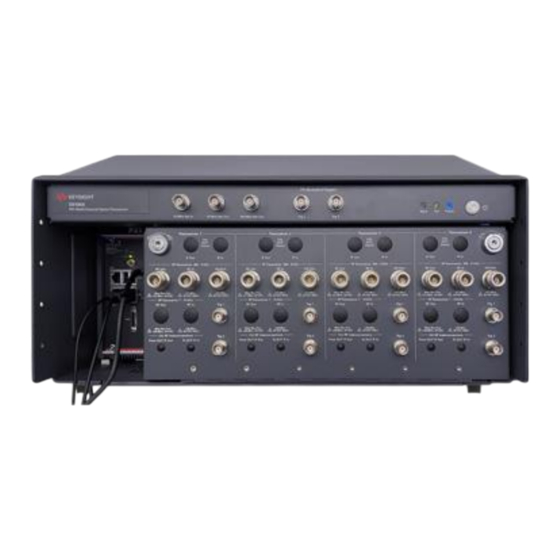
S9106A-2IF
Describes the Keysight S9106A-2IF, -4UP, and -42D 5G FR1 Multi-port Transceiver Solutions which are
streamlined, non-signaling measurement systems that enable automated testing of 5G New Radio (5G NR)
infrastructure equipment:
•
S9106A-2IF 5G FR1 Multi-port Transceiver contains: two Transceiver Channels, 380 MHz to 6 GHz,
with MIMO Subsystem and 7 to 15 GHz High IF on Two Channels
•
S9106A-4UP 5G FR1 Multi-port Transceiver contains: four Transceiver Channels, 380 MHz to 6 GHz,
with MIMO Subsystem
•
S9106A-42D 5G FR1 Multi-port Transceiver contains: four Transceiver Channels, 380 MHz to 6 GHz,
with MIMO Subsystem and 7 to 15 GHz High IF on Two Channels
S9106A-4UP
S9106A-42D
STARTUP GUIDE
Advertisement
Chapters
Table of Contents

Related Manuals for Keysight S9106A-2IF


Summary of Contents for Keysight S9106A-2IF
-
Page 1: S9106A-2If, -4Up, And -42D 5G Fr1 Multi-Port Transceiver Solutions
380 MHz to 6 GHz and 7 to 15 GHz S9106A-2IF S9106A-4UP S9106A-42D Describes the Keysight S9106A-2IF, -4UP, and -42D 5G FR1 Multi-port Transceiver Solutions which are streamlined, non-signaling measurement systems that enable automated testing of 5G New Radio (5G NR) infrastructure equipment: •... -
Page 2: Warranty
Notices WARRANT THIRD-PARTY SYSTEM- DFARS and are set forth specifically in LEVEL (COMBINATION OF CHASSIS, writing elsewhere in the EULA. Keysight © Keysight Technologies, Inc. 2024 CONTROLLERS, MODULES, ETC.) shall be under no obligation to update, No part of this manual may be PERFORMANCE, SAFETY, OR revise or otherwise modify the Software. -
Page 3: Table Of Contents
Contents S9106A-2IF, -4UP, and -42D 5G FR1 Multi-Port Transceiver Solutions 1 Overview 2 Review Safety Requirements 2. 1 Warning Statements and Symbols 2. 2 Safety 2. 3 Weight and Dimensions 2. 4 Handling and Lifting 2. 5 Cleaning 2. 6 Environmental Conditions (Operating) 2. - Page 4 6. 1. 1 Connect AC Power Cords & Power On Equipment 6. 1. 2 Verify X-Apps Controls S9106A-2IF RF Ports at 3 GHz 6. 1. 3 Verify X-Apps Controls S9106A-2IF High IF Ports at 10 GHz 6. 2 S9106A-4UP: Detailed Steps to Verify Operation 6.
-
Page 5: Overview
1 Overview 1 Overview Keysight S9106A-2IF, -4UP, and -42D 5G FR1 Multi-port Transceiver Solutions are streamlined, non-signaling measurement systems that enable automated testing of 5G New Radio (5G NR) infrastructure equipment. S9106A-2IF 5G FR1 S9106A-4UP 5G FR1 S9106A-42D 5G FR1 Multi-port Transceiver contains: Multi-port Transceiver contains: Multi-port Transceiver two Transceiver Channels, four Transceiver Channels,... - Page 6 S9106A-2IF, -4UP, and -42D 5G FR1 Multi-port Transceiver Solutions, Startup Guide...
-
Page 7: Review Safety Requirements
Do not proceed beyond a WARNING notice until the indicated conditions are fully understood and met. S9106A-2IF, -4UP, and -42D 5G FR1 Multi-port Transceiver Solutions, Startup Guide... -
Page 8: Safety
Voltage Directive) as well as current editions of the following standards (dates and editions are cited in the Declaration of Conformity): IEC/EN 61010-1 2. 2. 2 Acoustic Statement (European Machinery Directive) Acoustic noise emission LpA <70 dB Operator position Normal operation mode per ISO 7779 S9106A-2IF, -4UP, and -42D 5G FR1 Multi-port Transceiver Solutions, Startup Guide... - Page 9 AC Mains because it serves as a ground and helps protect the chassis and modules from electrostatic damage. S9106A-2IF, -4UP, and -42D 5G FR1 Multi-port Transceiver Solutions, Startup Guide...
-
Page 10: Weight And Dimensions
Weight: 18.1 kg (40 lbs) 2. 4 Handling and Lifting Use both side handles when lifting the S9106A Base System or E7770A Common Interface Unit (CIU). Use a rolling cart when transporting the S9106A Base System or E7770A Common Interface Unit (CIU). S9106A-2IF, -4UP, and -42D 5G FR1 Multi-port Transceiver Solutions, Startup Guide... -
Page 11: Cleaning
2 Review Safety Requirements 2. 5 Cleaning Clean the outside of Keysight products with a soft, lint-free, slightly dampened cloth. Do not use detergent or chemical solvents. To prevent electrical shock, disconnect from Mains before cleaning. Use a dry cloth or one slightly dampened with water to clean the external case parts. -
Page 12: Environmental Conditions (Operating)
The Keysight S9106A-2IF, -4UP, and -42D 5G FR1 Multi-port Transceiver Solutions are designed for use in Installation Category II and Pollution Degree 2. The Keysight S9106A-2IF, -4UP, and -42D 5G FR1 Multi-port Transceiver Solutions are designed for use in the following conditions: For indoor use only Altitude up to 6,561.68 ft (2,000 m) Operating Temperature 10 to 40°... -
Page 13: Ventilation
10°C from the lowest, of the maximum operating temperature of a single instrument. If there are any concerns or special requirements, a Keysight Field Engineer should be consulted to assure instrument(s) temperature compliance and performance. -
Page 14: Location And Mounting
Consider ergonomics when locating any keyboard or mouse which will be used in connection with an instrument. Install the Keysight S9106A-2IF, -4UP, and -42D 5G FR1 Multi-port Transceiver Solutions so that the detachable power cords are readily identifiable and is easily reached by the operator. The detachable power cord is the disconnecting device. -
Page 15: Power Requirements
"NOTE: The input terminals for this product are classified as Measurement Category None." The Keysight S9106A-2IF, -4UP, and -42D 5G FR1 Multi-port Transceiver Solutions do not contain customer serviceable fuses. Failure to ground the test set properly can result in personal injury. - Page 16 2. 9. 4 Do Not Use Extension Cords DO NOT use extension cords to power your equipment. 2. 9. 5 Do Not Use Converters or Adapters DO NOT use any converters or adapters. S9106A-2IF, -4UP, and -42D 5G FR1 Multi-port Transceiver Solutions, Startup Guide...
- Page 17 2. 9. 7 Avoid Loose Connection DO NOT use outlet if the power cord makes a loose connection. 2. 9. 8 Make Proper Connection DO NOT allow plug to bend down or become loose. S9106A-2IF, -4UP, and -42D 5G FR1 Multi-port Transceiver Solutions, Startup Guide...
-
Page 18: Ac Power Cord
5G FR1 Multi-port Transceiver Solutions cabinet when connected to an appropriate power line outlet. Use the Keysight supplied power cord or one with the same or better electrical rating. The cable appropriate to the original shipping location is included with the Keysight S9106A-2IF, -4UP, and -42D 5G FR1 Multi-port Transceiver Solutions. See: http://www.keysight.com/find/powercords... -
Page 19: Protecting Against Electrostatic Discharge (Esd)
Shipping Materials and ESD Keysight’s chassis and instrument modules are shipped in materials which prevent static electricity damage. These instruments should only be removed from the packaging in an anti-static area, ensuring that correct anti-static precautions are taken. -
Page 20: Front And Rear Panel Symbols
2 Review Safety Requirements 2. 12 Front and Rear Panel Symbols Symbols that may be on the exterior of S9106A-2IF, S9106A-4UP, and S9106A-42D hardware components are: Symbol Description This symbol is used to indicate power ON and to mark the position of the instrument power line switch. - Page 21 Please refer to www.keysight.com/go/takeback to understand your Trade in options with Keysight in addition to product takeback instructions. China Restricted Substance Product Label. The EPUP (environmental protection use period) number in the center indicates the time period during which no hazardous or toxic substances or elements are expected to leak or deteriorate during normal use and generally reflects the expected useful life of the product.
-
Page 22: Returning For Service
Should it become necessary to return the system for repair or service, follow these steps: 1. Review the warranty information shipped with the product. 2. Contact Keysight to obtain a Return Material Authorization (RMA) and a return address. For assistance finding Keysight contact information, go to: www.keysight.com/find/assist... -
Page 23: Review Hardware
Hardware Components on page 24 Connector Descriptions on page 26 Connectors, 10 MHz Ref In/Out on the Rugged Front Panel on page 26 Connectors, S9106A-2IF on the Rugged Front Panel on page 27 Connectors, S9106A-4UP on the Rugged Front Panel on page 28 Connectors, S9106A-42D on the Rugged Front Panel on page 29 Connectors, S9106A-2IF, -4UP, and -42D on the PXIe Chassis Rear Panel on page 31 Connectors, E7770A Common Interface Unit (CIU) for the S9106A-2IF and S9106A-42D 5G FR1 Multi-port Transceiver on page 33 S9106A-2IF, -4UP, and -42D 5G FR1 Multi-port Transceiver Solutions, Startup Guide... -
Page 24: Hardware Components
Tx channels or four Rx channels. All four channels can operate in the FR1 RF frequency range. FR1 RF frequencies ranging from 380 MHz to 6 GHz This system can be configured for 2x2 or 4x4 MIMO measurements in the FR1 RF frequency range. S9106A-2IF, -4UP, and -42D 5G FR1 Multi-port Transceiver Solutions, Startup Guide... - Page 25 High IF frequencies from 7 to 15 GHz This system can be configured for 2x2 or 4x4 MIMO measurements in the FR1 RF frequency range, or 2x2 MIMO measurements in the High IF frequency range. S9106A-2IF, -4UP, and -42D 5G FR1 Multi-port Transceiver Solutions, Startup Guide...
-
Page 26: Connector Descriptions
0 to 10 dBm, nominal The 10 MHz Ref In connector frequency range, on S910xA systems, is different from the M9300A PXIe Frequency Reference Data Sheet. The S910xA systems only support 10 MHz or 100 MHz inputs. S9106A-2IF, -4UP, and -42D 5G FR1 Multi-port Transceiver Solutions, Startup Guide... -
Page 27: Connectors, S9106A-2If On The Rugged Front Panel
Trig 1 and Trig 2 (Input or Output, Selectable) Connectors BNC (f) Input Impedance 1 kΩ or 50 Ω, nominal Input Level Range –3.3 V to +3.3 V Output Impedance 50 Ω, nominal Output Level Range 3.3 V LVTTL S9106A-2IF, -4UP, and -42D 5G FR1 Multi-port Transceiver Solutions, Startup Guide... -
Page 28: Connectors, S9106A-4Up On The Rugged Front Panel
Trig 1 and Trig 2 (Input or Output, Selectable) Connectors BNC (f) Input Impedance 1 kΩ or 50 Ω, nominal Input Level Range –3.3 V to +3.3 V Output Impedance 50 Ω, nominal Output Level Range 3.3 V LVTTL S9106A-2IF, -4UP, and -42D 5G FR1 Multi-port Transceiver Solutions, Startup Guide... -
Page 29: Connectors, S9106A-42D On The Rugged Front Panel
Trig 1 and Trig 2 (Input or Output, Selectable) Connectors BNC (f) Input Impedance 1 kΩ or 50 Ω, nominal Input Level Range –3.3 V to +3.3 V Output Impedance 50 Ω, nominal Output Level Range 3.3 V LVTTL S9106A-2IF, -4UP, and -42D 5G FR1 Multi-port Transceiver Solutions, Startup Guide... -
Page 30: Connectors, M9038A Pxie Embedded Controller
Blinking @ 1 Hz = Gen1 speed Blinking @ 2 Hz = Gen2 speed On steady = Gen3 speed LAN (White), Both LEDs are reserved for Keysight use only. USR (Grey) Video Display Port Connectors One DisplayPort++ connector Two Thunderbolt- 3 (TB1 &... -
Page 31: Connectors, S9106A-2If, -4Up, And -42D On The Pxie Chassis Rear Panel
3 Review Hardware 3. 2. 6 Connectors, S9106A-2IF, -4UP, and -42D on the PXIe Chassis Rear Panel AC Line Input (Use the AC line cord supplied with the S9106A.) Connector, Three- 100/120 V, 50/60 Hz, Prong 1200 W MAX (Lower range) 220/240 V, 50/60 Hz,... - Page 32 System Timing Module. To provide a 10 MHz Clock to the S9106A, Connectors, 10 MHz Ref In/Out on the Rugged Front Panel on page 26. For additional information, see the Data Sheet for the Keysight M9019A, 5992-1481EN. S9106A-2IF, -4UP, and -42D 5G FR1 Multi-port Transceiver Solutions, Startup Guide...
-
Page 33: Connectors, E7770A Common Interface Unit (Ciu) For The S9106A-2If And S9106A-42D 5G Fr1 Multi-Port Transceiver
Connector SMA (f), 50 Ω, nominal (Intended for future use.) LO Out Connector SMA (f), 50 Ω, nominal This connector supplies the local oscillator output for use with a second (independent) LO source. S9106A-2IF, -4UP, and -42D 5G FR1 Multi-port Transceiver Solutions, Startup Guide... -
Page 34: Connectors, E7770A-Ld2 Ciu Lo Distribution Card
Auxiliary local oscillator output 4. LO In 2 Connector SMA (f), 50 Ω, nominal Input source used in configurations with multiple E7770A CIUs; this connection would be from the LO Card LO Out of a second E7770A CIU. S9106A-2IF, -4UP, and -42D 5G FR1 Multi-port Transceiver Solutions, Startup Guide... -
Page 35: Connectors, E7770A-Hb2 Ciu Channel Card, 7 To 15 Ghz High If
DL IF input for Channel B. DUT IF In/Out B Connector SMA (f), 50 Ω, nominal In/Out connection for Channel B. IF Out B Connector Type-N (f), 50 Ω, nominal UL IF output for Channel B. S9106A-2IF, -4UP, and -42D 5G FR1 Multi-port Transceiver Solutions, Startup Guide... -
Page 36: Connectors, E7770A Ciu Rear Panel
Mains switch where the AC power cable is connected. Since the E7770A-LA2 CIU LO Card and the E7770A-LD2 CIU LO Distribution Card do not extend through to the rear panel, there are no rear connections for these two cards. S9106A-2IF, -4UP, and -42D 5G FR1 Multi-port Transceiver Solutions, Startup Guide... -
Page 37: Connectors, E7770A Ciu Rear Panel, Channel Cards
In the S9106A-2IF 5G FR1 Multi-port Transceiver and S9106A-42D 5G FR1 Multi-port Transceiver configurations, only rear panel connectors for CHANNEL 1A and CHANNEL 1B are usable with the E7770A-HB2 CIU Channel Card, 7 to 15 GHz High IF. LO/CTRL/PWR - Not used with S9106A-2IF, S9106A-4UP, and S9106A- 42D. Connector TNC (f), 50 Ω, nominal Local oscillator, control, and power from... -
Page 38: Connectors, E7770A Ciu Rear Panel, Controller Card
BNC (f), 50 Ω, nominal Input Level Range 5 V TTL (See description for TRIG 1.) Ctrl 1 Connector Micro-HDMI Reserved for Keysight internal use only. Ctrl 2 Connector Micro-HDMI Reserved for Keysight internal use only. S9106A-2IF, -4UP, and -42D 5G FR1 Multi-port Transceiver Solutions, Startup Guide... -
Page 39: Install Hardware
Tx channels or four Rx channels. All four channels can operate in the FR1 RF frequency range. FR1 RF frequencies ranging from 380 MHz to 6 GHz This system can be configured for 2x2 or 4x4 MIMO measurements in the FR1 RF frequency range. S9106A-2IF, -4UP, and -42D 5G FR1 Multi-port Transceiver Solutions, Startup Guide... - Page 40 FR1 RF frequencies ranging from 380 MHz to 6 GHz or High IF frequencies ranging from 7 to 15 GHz This system can be configured for 2x2 or 4x4 MIMO measurements in the FR1 RF frequency range or 2x2 MIMO measurements in the High IF frequency range. S9106A-2IF, -4UP, and -42D 5G FR1 Multi-port Transceiver Solutions, Startup Guide...
-
Page 41: Keysight S9106A-2If 5G Fr1 Multi-Port Transceiver
4 Install Hardware 4. 2 Keysight S9106A-2IF 5G FR1 Multi-port Transceiver S9106A-2IF, -4UP, and -42D 5G FR1 Multi-port Transceiver Solutions, Startup Guide... - Page 42 SMA (m) to Type-N (m), 1100 mm (43.3 in) Transceiver 1, CIU RF Interconnections Connect E7770A-HB2 CIU CHANNEL 1A, DUT IF OUT (rear panel) to S9106A-2IF labeled: "From DUT IF Out" (front panel). Connect E7770A-HB2 CIU CHANNEL 1B, DUT IF IN (rear panel) to S9106A-2IF labeled: "To DUT IF In" (front panel).
-
Page 43: Connect Cables, Lan Cables, A Display, A Keyboard & Mouse
2. Connect LAN 1 (top) to the Site LAN at your facility. 3. Connect LAN 2 (bottom) to the E7770A CIU CONTROL (rear panel). ➅ 4. Connect a Display, Keyboard & Mouse (Not included with S9106A-2IF). S9106A-2IF, -4UP, and -42D 5G FR1 Multi-port Transceiver Solutions, Startup Guide... -
Page 44: Connect Ac Power Cords & Power On Equipment
1. Power on the E7770A CIU Rear Mains Switch, located on the rear panel. 2. Power on the E7770A CIU AC Power Switch, located on the left front panel. 3. Power on the S9106A-2IF AC Power Switch, located on the right front panel. S9106A-2IF, -4UP, and -42D 5G FR1 Multi-port Transceiver Solutions, Startup Guide... -
Page 45: Keysight S9106A-4Up 5G Fr1 Multi-Port Transceiver
one 5063-1530 RF Cable, SMA (m) to SMA (m), 152.4 mm (6.0 two 1250-1250 Adapters, SMA (f) to Type-N (m) Remove this loop-back cable from all RF ports and HD ports dur- ing normal use. S9106A-2IF, -4UP, and -42D 5G FR1 Multi-port Transceiver Solutions, Startup Guide... -
Page 46: Connect Cables, Lan Cables, A Display, A Keyboard & Mouse
3. Connect a Display, Keyboard & Mouse (Not included with S9106A-4UP). 4. 3. 2 Connect AC Power Cord & Power On Equipment Power on the S9106A-4UP AC Power Switch, located on the right front panel. S9106A-2IF, -4UP, and -42D 5G FR1 Multi-port Transceiver Solutions, Startup Guide... -
Page 47: Keysight S9106A-42D 5G Fr1 Multi-Port Transceiver
4 Install Hardware 4. 4 Keysight S9106A-42D 5G FR1 Multi-port Transceiver S9106A-2IF, -4UP, and -42D 5G FR1 Multi-port Transceiver Solutions, Startup Guide... - Page 48 Connect E7770A-HB2 CIU CHANNEL 1B, DUT IF IN (rear) to S9106A-42D labeled: "To DUT IF In" (front panel). Transceiver 2, CIU RF Interconnections Connect E7770A-HB2 CIU CHANNEL 2A, DUT IF OUT (rear) to S9106A-42D labeled: "From DUT IF Out" (front panel). S9106A-2IF, -4UP, and -42D 5G FR1 Multi-port Transceiver Solutions, Startup Guide...
-
Page 49: Connect Cables, Lan Cables, A Display, A Keyboard & Mouse
2. Connect LAN 1 (top) to the Site LAN at your facility. 3. Connect LAN 2 (bottom) to the E7770A CIU CONTROL (rear panel). ➅ 4. Connect a Display, Keyboard & Mouse (Not included with S9106A-42D). S9106A-2IF, -4UP, and -42D 5G FR1 Multi-port Transceiver Solutions, Startup Guide... -
Page 50: Connect Ac Power Cords & Power On Equipment
1. Power on the E7770A CIU Rear Mains Switch, located on the rear panel. 2. Power on the E7770A CIU AC Power Switch, located on the left front panel. 3. Power on the S9106A-42D AC Power Switch, located on the right front panel. S9106A-2IF, -4UP, and -42D 5G FR1 Multi-port Transceiver Solutions, Startup Guide... -
Page 51: Install Software
5 Install Software 5 Install Software Each S9106A-2IF, S9106A-4UP, and S9106A-42D standard configuration includes an M9038A PXIe Embedded Controller; all required software comes pre-installed. Proceed to Verify Operation on page 53. S9106A-2IF, -4UP, and -42D 5G FR1 Multi-port Transceiver Solutions, Startup Guide... - Page 52 S9106A-2IF, -4UP, and -42D 5G FR1 Multi-port Transceiver Solutions, Startup Guide...
-
Page 53: Verify Operation
All of the previous sections must be completed before verifying operation of the S9106A-2IF, S9106A-4UP, or the S9106A-42D. Each module has its own instance of X-Apps, so the S9106A-2IF system will have two instances of X-Apps running while the S9106A-4UP and S9106A-42D systems will have four instances of X-Apps running. -
Page 54: S9106A-2If: Detailed Steps To Verify Operation
3. Power on the E7770A CIU AC Power Switch, located on the left-front panel. 4. Connect an AC Power Cord to the S9106A Base System right-rear panel. 5. Power on the S9106A-2IF AC Power Switch, located on the left-front panel. The M9038A PXIe Embedded Controller and the M9300A PXIe Reference are part of the S9106A Base System;... -
Page 55: Verify X-Apps Controls S9106A-2If Rf Ports At 3 Ghz
S9106A-2IF 5G FR1 Multi-port Transceiver contains two M9410A PXIe VXTs that are labelled on the Rugged Front Panel as Transceiver 1 and Transceiver 2. 6. 1. 2 Verify X-Apps Controls S9106A-2IF RF Ports at 3 GHz This process verifies operation of RF Transceiver .380 - 6 GHz, located on the Rugged Front Panel. - Page 56 Each Mode runs within a screen (there can be multiple screens). Screens are shown as tabs across the top of the interface. IQ Analyzer Mode is included with the S9106A-2IF and appears as a tab with the label IQ Analyzer 1.
- Page 57 Select Input/Output from the drop-down menu panel (top-right corner), select RF Source tab, select RF Output Port drop-down menu, and select RF Output. b. Set RF Power to –10 dBm, Frequency to 3 GHz, and RF Output to On. S9106A-2IF, -4UP, and -42D 5G FR1 Multi-port Transceiver Solutions, Startup Guide...
- Page 58 RF Transceiver .380 - 6 GHz, RF Out ➀ RF In ➁ of the S9106A-2IF are working properly. (The power level is only approximate because there is loss in the cable being used and this loss is not being corrected during the measurement.)
-
Page 59: Verify X-Apps Controls S9106A-2If High If Ports At 10 Ghz
6 Verify Operation 6. 1. 3 Verify X-Apps Controls S9106A-2IF High IF Ports at 10 GHz This process verifies operation of the RF Transceiver 7 - 15 GHz, located on the Rugged Front Panel; RF Out ➃ RF In ➄ these connectors may be referred to as: "High IF" or "DUT IF". - Page 60 Select Input/Output from the drop-down menu panel (top-right corner), select RF Source tab, select RF Output Port drop-down menu, and select DUT IF OUT 1. b. Set RF Power to –10 dBm, Frequency to 10 GHz, and RF Output to On. S9106A-2IF, -4UP, and -42D 5G FR1 Multi-port Transceiver Solutions, Startup Guide...
- Page 61 RF Transceiver 7 - 15 GHz, RF Out ➃ RF In ➄ of the S9106A-2IF are working properly. (The power level is only approximate because there is loss in the cable being used and this loss is not being corrected during the measurement.)
-
Page 62: S9106A-4Up: Detailed Steps To Verify Operation
M9410A PXIe VXT Vector Transceiver and its selected X-Apps software pair in the system; the S9106A-4UP 5G FR1 Multi-port Transceiver contains four M9410A PXIe VXTs that are labelled on the Rugged Front Panel as Transceiver 1, Transceiver 2, Transceiver 3, and Transceiver 4. S9106A-2IF, -4UP, and -42D 5G FR1 Multi-port Transceiver Solutions, Startup Guide... -
Page 63: Verify X-Apps Controls S9106A-4Up Rf Ports At 3 Ghz
one 5063-1530 RF Cable, SMA (m) to SMA (m), 152.4 mm (6.0 in) and two 1250-1250 Adapters, SMA (f) to Type-N (m) 2. If it is not already running, start the Modular TRX software and review the interface; this interface is referred to as a Mode: S9106A-2IF, -4UP, and -42D 5G FR1 Multi-port Transceiver Solutions, Startup Guide... - Page 64 The Modular TRX interface can be started as follows: Select the Start menu (lower-left corner icon) > Scroll down to "K" applications > Select the Keysight Modular Transceiver drop-down arrow > Scroll down the list and select LaunchModularTRX Each Mode looks different and has its own collection of measurement capabilities, controls, windows, and SCPI commands.
- Page 65 Select Input/Output from the drop-down menu panel (top-right corner), select RF Source tab, select RF Output Port drop-down menu, and select RF Output. b. Set RF Power to –10 dBm, Frequency to 3 GHz, and RF Output to On. S9106A-2IF, -4UP, and -42D 5G FR1 Multi-port Transceiver Solutions, Startup Guide...
- Page 66 RF In ➁ of the S9106A-4UP are working properly. (The power level is only approximate because there is loss in the cable being used and this loss is not being corrected during the measurement.) S9106A-2IF, -4UP, and -42D 5G FR1 Multi-port Transceiver Solutions, Startup Guide...
-
Page 67: S9106A-42D: Detailed Steps To Verify Operation
3. Power on the E7770A CIU AC Power Switch, located on the left-front panel. 4. Connect an AC Power Cord to the S9106A Base System right-rear panel. 5. Power on the S9106A-2IF AC Power Switch, located on the left-front panel. The M9038A PXIe Embedded Controller and the M9300A PXIe Reference are part of the S9106A Base System;... -
Page 68: Verify X-Apps Controls S9106A-42D Rf Ports At 3 Ghz
S9106A-42D 5G FR1 Multi-port Transceiver. Use a cable with two adapters (or equivalent) such as: one 5063-1530 RF Cable, SMA (m) to SMA (m), 152.4 mm (6.0 in) and two 1250-1250 Adapters, SMA (f) to Type-N (m) S9106A-2IF, -4UP, and -42D 5G FR1 Multi-port Transceiver Solutions, Startup Guide... - Page 69 The Modular TRX interface can be started as follows: Select the Start menu (lower-left corner icon) > Scroll down to "K" applications > Select the Keysight Modular Transceiver drop-down arrow > Scroll down the list and select LaunchModularTRX Each Mode looks different and has its own collection of measurement capabilities, controls, windows, and SCPI commands.
- Page 70 Select Input/Output from the drop-down menu panel (top-right corner), select RF Source tab, select RF Output Port drop-down menu, and select RF Output. b. Set RF Power to –10 dBm, Frequency to 3 GHz, and RF Output to On. S9106A-2IF, -4UP, and -42D 5G FR1 Multi-port Transceiver Solutions, Startup Guide...
- Page 71 RF In ➁ of the S9106A-42D are working properly. (The power level is only approximate because there is loss in the cable being used and this loss is not being corrected during the measurement.) S9106A-2IF, -4UP, and -42D 5G FR1 Multi-port Transceiver Solutions, Startup Guide...
-
Page 72: Verify X-Apps Controls S9106A-42D High If Ports At 10 Ghz
S9106A-42D 5G FR1 Multi-port Transceiver. Use a cable with two adapters (or equivalent) such as: one 5063-1530 RF Cable, SMA (m) to SMA (m), 152.4 mm (6.0 in) and two 1250-1250 Adapters, SMA (f) to Type-N (m) S9106A-2IF, -4UP, and -42D 5G FR1 Multi-port Transceiver Solutions, Startup Guide... - Page 73 Select Input/Output from the drop-down menu panel (top-right corner), select RF Source tab, select RF Output Port drop-down menu, and select DUT IF OUT 1. b. Set RF Power to –10 dBm, Frequency to 10 GHz, and RF Output to On. S9106A-2IF, -4UP, and -42D 5G FR1 Multi-port Transceiver Solutions, Startup Guide...
- Page 74 RF In ➄ of the S9106A-42D are working properly. (The power level is only approximate because there is loss in the cable being used and this loss is not being corrected during the measurement.) S9106A-2IF, -4UP, and -42D 5G FR1 Multi-port Transceiver Solutions, Startup Guide...
-
Page 75: Mimo
All of the previous sections must be completed before performing MIMO measurements with the S9106A-2IF, S9106A- 4UP, or the S9106A-42D. To set up and run MIMO on the S9106A-2IF, S9106A-4UP, or the S9106A-42D. Refer to the Keysight MIMO Measurement Guide, M9410-90016 for the Keysight M9410A/M9411A VXT PXIe Vector Transceiver For DUT IF MIMO measurements, select the DUT IF ports. -
Page 76: Contacting Keysight
Is your product software up-to-date? Periodically, Keysight releases software updates to fix known defects and incorporate product enhancements. To search for software updates for your product, go to the Keysight Technical Support website at: www.keysight.com/find/techsupport Contacting Keysight Assistance with test and measurements and information on finding a local Keysight office are available at: www.keysight.com/find/assist...
Need help?
Do you have a question about the S9106A-2IF and is the answer not in the manual?
Questions and answers