Table of Contents
Advertisement
Quick Links
Advertisement
Table of Contents

Related Manuals for Cimel CE318-T


Summary of Contents for Cimel CE318-T
- Page 1 Multiband photometer CE318-T User’s Manual (rev. October 2021)
- Page 2 User Operation Manual Dear Customer and users, You have just purchased a Cimel photometer CE318-T and we would like to thank you. The CE318-T is the most recent model of the well-known Cimel CE318 photometer. This model is available and recommended to all users that intend to operate it in a network, such as AERONET, CARSNET or SONET.
-
Page 3: Table Of Contents
CE318-T Photometer User Operation Manual Table of Contents Product overview....................4 1.1. Presentation ......................4 1.2. System components quick description ..............5 1.3. Sensor head types ....................13 1.4. Data transmission ....................15 Installation ....................... 15 2.1. Installation site recommendations ................ 15 2.2. - Page 4 CE318-T Photometer User Operation Manual Factory calibration and maintenance ............69 6.1. Sensor head calibration and maintenance ............69 Calibration ........................69 Maintenance ........................ 69 6.2. Robot maintenance ....................70 Troubleshooting ....................70 7.1. Communication and data transfer is down ............70 Using serial port transfer protocol ................
-
Page 5: Product Overview
Due to its very low power consumption thanks to the MicroAmps technology, to its self-powered system and to its rugged design, the CE318-T fully meets the operational requirements of continuous monitoring in terms of reliability, long lifetime and very low maintenance cost. -
Page 6: System Components Quick Description
CE318-T Photometer User Operation Manual 1.2. System components quick description The photometer system is delivered with: 1. Control Unit (CU) The Control Unit is the component that received all the data acquired by the optical head and it is used as the user interface to parameterize the whole system running. - Page 7 CE318-T Photometer User Operation Manual 2. Sensor head and collimator a. The sensor head The sensor head measures the received signal from the sun, sky, soil or sea. Then it is sent and recorded to the CU. Detectors can be either silicon and. InGaAs detector is used for near-infrared wavelengths.
- Page 8 CE318-T Photometer User Operation Manual b. Collimator The collimator is a component that enables the light to be guided correctly to the sensor head outside lenses. The collimator helps to reduce the stray light. 1: notch 2: tightening screw 3: alignment hole 4: spot 3.
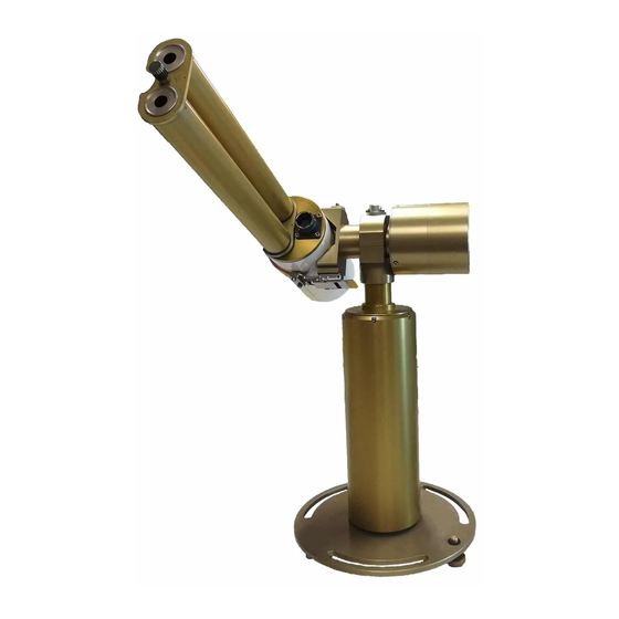
- Page 9 CE318-T Photometer User Operation Manual 4. Tripod and tray The tripod is the supplied infrastructure where the protection case and the robot are fixed and that enables the whole system to be stably fixed on the ground. The tray is a part fixed horizontally on the tripod and where the robot will be fixed on.
- Page 10 CE318-T Photometer User Operation Manual 5. Protection case with solar panel In order to isolate the CU and the batteries from external conditions they must be placed inside the weatherproof case. The solar panel that powers the system is incorporated in the case. The output plug of the solar panel is a RJ11 connector.
- Page 11 CE318-T Photometer User Operation Manual 6. Wet sensor The wet sensor detects rain in order to stop measurements and protect the sensor head from water when it is raining. The output plug of the sensor is a RJ11 connector. Standard length of the wire is 3m.
- Page 12 CE318-T Photometer User Operation Manual 8. Batteries and charger The black batteries supply power to the CU. The battery is 8AH. The YUASA battery is furnished when the satellite transmitter is used. The battery is 24AH. The Mascot 2240 battery charger is provided in case of powering the device through mains.
- Page 13 The satellite transmitter is useful in remote places where no reliable PC is available. It enables sending the data directly to an appropriate geostationary satellite which has a dedicated transmission channel for the CIMEL photometers. 1: Solar Panel Solartek 2: YAGI antenna 3: Mast Revision V4.10 October 2021...
-
Page 14: Sensor Head Types
CE318-T Photometer User Operation Manual 1.3. Sensor head types 6 different sensor head types exist: • Standard / CE318-TS9: It uses 340, 380, 440, 500, 675, 870, 937, 1020 and 1640 nm filters (Fig.1). • Polarized / CE318-TP9: A filter wheel containing 3 sets of 3 polarizers operating in infrared (POL1), Ultraviolet (POL2), and visible (POL3) and which are orientated with a 120°... - Page 15 CE318-T Photometer User Operation Manual Figure 1 : Standard type (CE318-TS9) Figure 2 : BRDF Type (CE318-TU9) Figure 3 : POLARIZED type (CE318-TP9) 490 nm 440 nm 415 nm Figure 4 : BRDF 12 filters type Figure 5 : Ocean Color 12 filters...
-
Page 16: Data Transmission
CE318-T Photometer User Operation Manual 1.4. Data transmission The photometer can use 4 different communication protocols to send its data from the • PC data transfer using a RS232 link to an acquisition PC. (Default data transmission). The PC is not provided. -
Page 17: Needed Tools
CE318-T Photometer User Operation Manual Needed tools To install the system, the following tools are needed: • Open-end wrench size 10. • Open wrench size 13. If possible, a tubular spirit level will be used in addition of the robot spirit level to make the installation easier (0.4mm/m accuracy). - Page 18 CE318-T Photometer User Operation Manual 6. Attach the tripod feet to the ground with appropriate screws. Note: Orientate the protection case emplacement South if the location is in the Northern hemisphere or North if the location is in the Southern Hemisphere.
-
Page 19: Case Mounting
CE318-T Photometer User Operation Manual Case mounting 7. Insert the 4 ribs into the metallic frame in order to fix the case. 8. Tight strongly the screw into the ribs with the inside of the case in between. 9. Put the foam at the bottom of the case and on the sides, place the batteries and the CU as shown on the picture below. -
Page 20: Robot And Sensor Head Mounting
CE318-T Photometer User Operation Manual Robot and sensor head mounting 10. Put the screws into white plastic part. 11. Put the screws on the holes through the robot base but don’t tight them to the end, let a 2 or 3 cm backlash so that the levelling that is done in the next part is easier to do. - Page 21 CE318-T Photometer User Operation Manual 13. Launch a Park scenario in the CU menu. The robot will find its zero position. 14. Set the horizontal robot axis in the East-West direction by manually turning the whole base of the robot.
- Page 22 CE318-T Photometer User Operation Manual 15. Assemble the collimator to the sensor head front plates by tightening strongly the long central threaded rod using a plier. The notch must face the 4 quadrants lens on the sensor head front plate.
- Page 23 CE318-T Photometer User Operation Manual 17. Plug the sensor head cord from the CU to the sensor head passing it through the cap and attaching it to the pig tail. Connect the computer or the transmitter to the DCP input on the removable terminal block via a RS232 to RJ11 cable.
- Page 24 CE318-T Photometer User Operation Manual 18. Level the robot up so that it’s perfectly horizontal by playing on both precision wheels until the spirit level on the top of the robot is centered. This part is a little tricky and may take few trials. Using an additional tubular sprit level may facilitate this step.
- Page 25 CE318-T Photometer User Operation Manual 20. Launch a Park scenario in the CU menu. The photometer head will find its PARK position which is the nadir on the polar angle (head orientated down). If the head is pointing to zenith (orientated up), unstrap the sensor head, reposition it in the opposite sense in the straps and do step 13 again.
- Page 26 CE318-T Photometer User Operation Manual 21. Launch a GOSUN scenario in the CU menu. The sensor head is going to point the sun. Polar and Azimuthal values are displayed in degree on the CU screen. After a GOSUN scenario the sun spot may not be centered on the target.
- Page 27 CE318-T Photometer User Operation Manual After having done the corrections, repeat steps 20 and 21 to check again the position of the sun spot. Repeat the correction until the sun spot is almost perfectly centered on the target (few millimeters off maximum).
- Page 28 CE318-T Photometer User Operation Manual 26. Set the photometer in automatic mode. Revision V4.10 October 2021...
-
Page 29: Optional Pyranometer Global Radiation Sensor
CE318-T Photometer User Operation Manual Optional pyranometer global radiation sensor The photometer is ready to receive an optional external pyranometer for global radiation (RG) measurements. Please refer to the Pyranometer manufacturer for the field installation. Take care to not install the Pyranometer in the Photometer field of view. -
Page 30: Communication Protocol Installation And Setup
Plug the RS232 link to the dedicated PC (already done in installation part) • Install PhotoGetData on the computer The software is provided on the USB stick sent with the instrument and can be downloaded on Cimel website. • Launch PhotoGetData. In the tools → configuration menu: In the communication tab: →Choose Serial in the communication type and choose the Port COM associated to... -
Page 31: Usb Communication
(See with the local pc expert). USB communication 2.3.2.1. Software configuration The user should install the USB driver provided by Cimel (see PhotoGetData manual). Plug the USB cable to the dedicated PC. Install PhotoGetData. The software is Revision V4.10 October 2021... -
Page 32: Communication Over Gprs
CE318-T Photometer User Operation Manual provided on the USB stick sent with the instrument and can be downloaded on Cimel website. Launch PhotoGetData. In the tools → configuration menu: In the communication tab: →Choose USB in the communication type photometer. - Page 33 CE318-T Photometer User Operation Manual 2.3.3.1. CE1201A SIM card insertion SIM card 2.3.3.2. CE1701A SIM card insertion 2.3.3.3. FTP over GPRS The CU could upload its data automatically to an FTP server. The CU initiates the transmission, it automatically connects to Internet on the user’s FTP server and uploads the data.
- Page 34 CE318-T Photometer User Operation Manual The user may use their chosen FTP server. They must enter the user’s name and password and specify the name of the directory where the data will be uploaded. 2.3.3.3.1. Parameters configuration Some of these settings cannot be edited / modified on the CU. PhotoGetData has to be used to modify them.
- Page 35 CE318-T Photometer User Operation Manual • TLS_RSA_WITH_AES_256_CBC_SHA • TLS_RSA_WITH_AES_128_GCM_SHA256 The Cypher suite is automatically negotiated between the server and the AU. 2.3.3.4.2. Parameters configuration Some of these settings cannot be edited / modified on the CU. PhotoGetData has to be used to modify them.
- Page 36 CE318-T Photometer User Operation Manual • PATH: /path1/path2 • PORT: 2020 (If the port is not present in the URL, set 80 for HTTP and 443 for HTTPS). 2.3.3.4.4. POST request sent by the CU To upload the k8 data file the CE318T submit a http form using a POST request on the HTTP(S) server.
-
Page 37: Satellite Transmission Installation And Configuration
CE318-T Photometer User Operation Manual Satellite transmission installation and configuration The satellite transmission of the data is done using a Satlink 2 logger and transmitter model SL2-G312-1 and a YAGI antenna. The satellite which will receive and transmit the data depends on the geographic location, it can be GOES, MSG… the satellite has dedicated communication channel that can be attributed to the Satlink2. - Page 38 CE318-T Photometer User Operation Manual 4. Slide the stirrup through the mast until it gets to the end position. 5. Insert the V-shaped part in the stirrup extremities with the mast in between and tight strongly the nuts. 6. Insert the stirrup extremities in the V-shaped part with the tubular metallic part in between to fix it.
- Page 39 CE318-T Photometer User Operation Manual 9. Tight the 4 nuts. 10. Insert the YAGI antenna into its support. Orientate the antenna to the right polar angle. 11. Insert the screw in both the YAGI antenna support and the Antenna and tight the nut to the opposite side.
- Page 40 CE318-T Photometer User Operation Manual 14. Insert the fixing flats into the white screws until it gets in contact with the mast and tight the 2 nuts. 15. Insert the screws in the holes of the V-shaped part according to the tilt angle wished for the solar panel (step 17).
- Page 41 CE318-T Photometer User Operation Manual 18. Insert the screws in the solar panel slides. 19. Insert those screws in the panel braces. 20. Tight the bolts to fix the solar panel properly. 21. YAGI antenna assembled. Revision V4.10 October 2021...
- Page 42 CE318-T Photometer User Operation Manual 22. Connect the transmitter RF Output to the antenna with a RG-8 cable (not provided). Connect the photometer DCP output to the transmitter RS232 input with the appropriate cable and adaptor. Power the transmitter using the regulator, the 12 V batteries and the solar panel.
-
Page 43: Control Unit Firmware Update
CE318-T Photometer User Operation Manual o DCP Config: Configure the Satlink 2 through the AU. [OFF; ON]: ON. o DCP Channel: DCP assigned channel. [0; 266]: 0. o DCP Type: Type of the used satellite. [METEOSAT, GOES 100, GOES 300, GOES 1200, Japan GMS, Feng Yun FY, India INSAT]: METEOSAT. -
Page 44: Menu Description
CE318-T Photometer User Operation Manual 3.3. Menu description The menu system is a hierarchical menu system. The actual menu structure design is defined by the current firmware version: V2.4.6. The menu design could be modified in the future. The main menu is composed of the following parameters: •... - Page 45 CE318-T Photometer User Operation Manual ALMUCANTAR ALMUCANTAR ALMUCANTAR ALMUCANTAR PPLAN PPLAN PPLAN PPLAN LTRACK SUN POL. ALMUCANTAR CIRCLE SKY CALIBRATE POL. PPLAN LTRACK SUN LTRACK SUN BCLSUN POL. HYBRID SKY CALIBRATE SKY CALIBRATE BCLSKY LTRACK SUN BCLSUN BCLSUN CROSS SKY CALIBRATE...
-
Page 46: Measures
CE318-T Photometer User Operation Manual Note 1: A scenario cannot be launch in manual mode if an automatically started scenario is running. If the SCENARIO menu is accessed while an automatic scenario is running, the current action of the CU will be displayed (GOSUN, SUN…). -
Page 47: Settings
CE318-T Photometer User Operation Manual 3.7. SETTINGS List and description of the parameters in the SETTINGS menu (default value in bold). These parameters are common to all photometers types except when mentioned. • Auto: Enable or disable automatic measurement. The internal scheduler is executed automatically [OFF;... - Page 48 CE318-T Photometer User Operation Manual ▪ H23: Enable CSD communication between 23h00 and 23h59. [OFF; ON]: OFF. o [GPRS] ▪ ACT: Select the modem network ACcess Technology. [AUTO, 2G, 3G]: AUTO. ▪ APN: Access Point Name provided by the network operator to access internet.
-
Page 49: Date
The CU date and time can be set manually via the “DATE” menu. After the modification, exit from this menu. A dialog message appears and asks to confirm the modification. 3.9. CIMEL Here is a list and description of the parameters in the CIMEL menu: • TSV: displays True Solar Time. •... -
Page 50: Info
CE318-T Photometer User Operation Manual and the Satlink 2. • Password: not used menu. (¹): The first time, the GPS may take up to 15 min to get the GPS information. Coordinates are checked daily at 01:00 True Solar Time. The coordinates are automatically updated if the photometer has been moved over one tenth of a degree in longitude or/and latitude. - Page 51 CE318-T Photometer User Operation Manual Filters used and their sequence (i for InGaAs channel) Standard / Polarized BRDF BRDF 12 filters ocean color / lake color 1020 nm 1020 nm 1020 nm 1020 nm 1640i nm 1640i nm 1640i nm...
- Page 52 CE318-T Photometer User Operation Manual 870 nm SKY 1020 nm SKY POL IR 0-1-2-3 1640i nm SKY 702 nm AUR 442 nm AUR 675 nm SKY 1640i nm SKY 870 nm SKY 415 nm AUR 412 nm AUR 440 nm SKY...
- Page 53 CE318-T Photometer User Operation Manual ALMU (Standard, BRDF) / ALMUP (Polarized): The ALMUcantar technique consists in measuring the sky radiance in aerosol channels, keeping a constant polar angle equal to the zenith solar angle with varying azimuthal angle. In the ALMU scenario, azimuthal angles vary from 0° to +180° for an almucantar right and 0°...
- Page 54 CE318-T Photometer User Operation Manual Filters used and their sequence (i for InGaAs channel) Standard Polarized BRDF BRDF 12 filters ocean color / lake color 1020 nm 1020 nm SKY POL IR 0-1-2-3 1020 nm 1020 nm 1020 nm 1640i nm...
- Page 55 CE318-T Photometer User Operation Manual 380 nm 380 nm SKY POL UV 0-1-2-3 740 nm 550 nm 510 nm 340 nm SKY POL UV 0-1-2-3 1020i nm 1020i nm 490 nm 782 nm 442 nm 740 nm 412 nm 702 nm...
- Page 56 CE318-T Photometer User Operation Manual Filters used and their sequence (i for InGaAs channel) Standard Polarized BRDF BRDF 12 filters ocean color / lake color 1020 nm 1020 nm SKY POL IR 0-1-2-3 1020 nm 1020 nm 1020 nm 1640i nm...
- Page 57 CE318-T Photometer User Operation Manual CROSS SUN / MOON: The Cross Sun / Moon scenario consists in measuring sun or moon irradiance in 2 bands for several angles close to the sun / moon, using a cross scheme. In Cross Sun / Moon scenario: •...
- Page 58 CE318-T Photometer User Operation Manual CIRCLE (only with BRDF/CE318-TU photometers): The CIRCLE scenario consists in measuring at the constant polar with varying azimuthal angles from 0 to 360° with 5° steps using SKY gains. Filters used and their sequence BRDF...
- Page 59 CE318-T Photometer User Operation Manual Filters used and their sequence ocean color / lake color 1020 nm 870 nm 779 nm / 709 nm 665 nm 620 nm 560 nm 510 nm 490 nm 442 nm 412 nm 400 nm / 681 nm SUNP (Polarized): The SUN Polarized scenario consists in measuring the Sun directly on all polarizers with all filters.
-
Page 60: Group Of Measurement Scenarios
CE318-T Photometer User Operation Manual Note 1: This scenario is only used to check the polarizers. MOONP (Polarized): The MOON Polarized scenario consists in measuring the Moon directly on all polarizers with all filters except 937, 380 and 340nm. Filters used and their sequence... -
Page 61: Day And Night Measurement Schedule In Auto Mode
CE318-T Photometer User Operation Manual 4.3. Day and night measurement schedule in Auto mode Standard (CE318-TS9) and polarized (CE318-TP9) The photometer follows a daily schedule of automatic actions. Some actions are triggered by the time of the day and some by the air mass which is related to the thickness of atmosphere the sun light has been through to get to the photometer (Langley times). - Page 62 CE318-T Photometer User Operation Manual Air mass 2.2 62.96° Group A Air mass 2.0 60° Group B Air mass 1.7 53.97° Group B Afternoon times Group 09H00 15H00 Group C 09H15 14H45 Group D 09H30 14H30 Group A 09H45 14H15...
-
Page 63: Brdf (Ce318-Tu9) And Brdf 12 Filters (Ce318-Tu12)
CE318-T Photometer User Operation Manual Night time measurements are executed if: • The moon phase is between the first and last quarter • Moon air mass is higher than 7 • Sun air mass is below -7. Sun air mass below -7 means that the sun is already set and far enough so that it is not lightening too much the sky. -
Page 64: Execution Time Of Scenario
CE318-T Photometer User Operation Manual 4.4. Execution time of scenario Name Standard Polarized BRDF BRDF12 Seaprism 3SUN 01:20 01:20 01:20 01:25 01:25 3LUN 01:20 01:20 01:20 01:25 01:25 Curv cross 00:30 00:30 00:30 00:30 00:30 Almucantar (Left + Right) 01:00... -
Page 65: On-Site Maintenance
CE318-T Photometer User Operation Manual On-site maintenance 5.1. Weekly check preventive maintenance Before making any preventive maintenance, switch the CU in manual mode (see part 3.7). Here is a procedure that should be done every week in order to prevent the occurrence of measurement, electronic or mechanical problems on the photometer. -
Page 66: Corrective Maintenance
CE318-T Photometer User Operation Manual 6. Disassemble the collimator from the sensor head. Check each channel inside the collimator for possible obstruction. If necessary, clean it with dry air or very carefully with a bottlebrush. It should be perfectly clean. - Page 67 CE318-T Photometer User Operation Manual 4. Loosen the 2 nuts maintaining the probe clamp 5. Withdraw the screw and the wet sensor with is wire from the protection case 6. Slide the wet sensor to get it back and replace it.
-
Page 68: Robot Levelling Adjustment
CE318-T Photometer User Operation Manual Robot levelling adjustment After a PARK scenario, even if the spirit level is well-centered, it might happen that the V-shape part of the robot is not perfectly horizontal. You can check with a leveler. If the case happens: 1. -
Page 69: Flash Memory Formatting
CE318-T Photometer User Operation Manual Flash memory formatting Flash memory can be formatted via a hidden menu by following this procedure: Revision V4.10 October 2021... -
Page 70: Factory Calibration And Maintenance
The sensor head internal humidity is dried by a desiccant bag. This value is reported in all GROUP statuses data. If that value become higher than 50%, with an increase of 1% per week during several weeks, the desiccant bag must be replaced. Cimel is using a Clariant DESI PAK ref B001603. -
Page 71: Robot Maintenance
CE318-T Photometer User Operation Manual 6.2. Robot maintenance Cimel recommends its customers to make maintenance on the robot every 36 to 48 months. It consists in: • Replacement of micro switches • Replacement of transmission belts • Full cleaning of transmission gears, greasing of transmission gears and aging. -
Page 72: Using Satellite Transmitter
Try another cable. • Try another port COM on the acquisition computer if possible If this procedure does not solve the problem, please contact CIMEL technical support. Using satellite transmitter The possible causes that may interrupt the communication between the photometer and the satellite are: •... -
Page 73: Battery Low
10.5V. When the CU is in shutdown, the batteries voltage must be upper than 11.5V to power on the CU. If this has not solved the problem, please contact Cimel technical support. GPRS – communication errors 7.4. To identify the possible cause of the GPRS communication error, there are two menus to help the user for a diagnostic. -
Page 74: Gprs Errors
CE318-T Photometer User Operation Manual The menu “CIMEL\MODEM\HTTP TEST” uploads a K8 file containing the CU settings on an HTTP server. The CU indicates how was finished the communication (HTTP OK or HTTP ERROR). In case of error, the CU indicates the server HTTP reply code at the end. -
Page 75: Ftp Communication Errors
FTP server. • Correct the server configuration and set up the CU with it. If this has not solved the problem, please contact Cimel technical support. HTTP(S) communication errors The possible causes that may lead to HTTP(S) communication errors: •... - Page 76 Components can be replaced by the owner after diagnosis has been established by CIMEL technical support. Never try to replace a component by yourself without CIMEL approval. However, the sensor head should never be disassembled as it will unset the sky and sun calibrations.
-
Page 77: Technical Specifications
CE318-T Photometer User Operation Manual Technical specifications 9.1. General Specification value Irradiance precision < 0.1% Field of view 1.3° Minimal scattering angle from the sun 2° Spectral range 340 to 1640 nm Optical filter drift < 1% / year Automated mount... -
Page 78: Dimensional Drawings
CE318-T Photometer User Operation Manual 9.2. Dimensional drawings Revision V4.10 October 2021... - Page 79 CE318-T Photometer User Operation Manual Revision V4.10 October 2021...
- Page 80 CE318-T Photometer User Operation Manual Revision V4.10 October 2021...
- Page 81 CE318-T Photometer User Operation Manual Revision V4.10 October 2021...
- Page 82 CE318-T Photometer User Operation Manual Revision V4.10 October 2021...
- Page 83 CE318-T Photometer User Operation Manual Revision V4.10 October 2021...
- Page 84 CE318-T Photometer User Operation Manual Revision V4.10 October 2021...
- Page 85 CE318-T Photometer User Operation Manual Revision V4.10 October 2021...
-
Page 86: 10 After-Sales Service And Customer Relations
172 rue de Charonne 75011 Paris FRANCE Phone: (+33) 143 487 933 Email: support@cimel.fr Cimel can use Skype and Team Viewer to provide technical support. When contacting us please indicate: • The reference and the serial number of your product. •... -
Page 87: 11 Annexes
In this packing list you will find all the detached pieces for the assembly of your photometer CE318-T. Item visual Description/Origin Package 1/2: Photometer Control unit CE318-T (Sun Sky Lunar) with 2 antennas (GSM/GPRS, GPS/GNSS) Sensor head equipped with an optical protection cap Biaxial robot with its 3 m cables (2 axes Azimuthal and Zenithal) - Page 88 CE318-T Photometer User Operation Manual Optical cleaning cloth USB Stick with: Software & Documentation Fly case for the transportation of the whole instrument except infrastructure Package 2/2: Tripod Infrastructure Tripod infrastructure with protection enclosure and built-in solar panel, and rain detector (resistive) with 3...
-
Page 89: Aeronet Network (Faq)
CE318-T Photometer User Operation Manual 11.2. AERONET network (FAQ) What is the AERONET network? The AERONET (AErosol RObotic NETwork) program is a ground-based remote sensing federation of networks established by NASA and PHOTONS. Data acquired by all the photometers are gathered by the central system and a large number of quality insured products are made available for public access. -
Page 90: What To Do When There Is A "Ingaas / Silicon Discrepancy
If this procedure does not solve the problem, it means that the sensor head cord is probably damaged. Please contact Cimel technical support for any damaged sensor head cord or if the procedure is not solving the problem. What to do when there is a “InGaAs / silicon discrepancy”? -
Page 91: What To Do When There Is Constant Humidity
• Check all external cables and wires especially the connections. If this procedure does not solve the problem, please contact CIMEL technical support. What to do when there is constant humidity? If the photometer is declared in AERONET network, “constant humidity” warning flags can be emitted.
Need help?
Do you have a question about the CE318-T and is the answer not in the manual?
Questions and answers