Table of Contents
Advertisement
Advertisement
Table of Contents

Related Manuals for Cimel CE318-T


Summary of Contents for Cimel CE318-T
- Page 1 Multiband photometer CE318-T User’s Manual (rev. January 2018)
- Page 2 Innovation and performance: we designed it so that it is always easy to use. In the line of Cimel products, you will also find a wide range of remote sensing instruments like the Cimel LiDAR CE370 and CE376 automatic aerosol LiDARs.
-
Page 3: Table Of Contents
CE318-T Photometer User Operation Manual Table of Contents Product overview....................4 1.1. Presentation ......................4 1.2. System components quick description ..............5 1.3. Sensor head types ....................13 1.4. Data transmission ....................14 Installation ....................... 15 2.1. Installation site recommendations ................ 15 2.2. - Page 4 CE318-T Photometer User Operation Manual 5.2.2. Robot levelling adjustment ..................62 5.2.3. Flash memory formatting ..................... 64 Factory calibration and maintenance ............64 6.1. Sensor head calibration and maintenance ............64 6.2. Robot maintenance ....................64 Troubleshooting ....................65 7.1.
-
Page 5: Product Overview
Due to its very low power consumption thanks to the MicroAmps technology, to its self-powered system and to its rugged design, the CE318-T fully meets the operational requirements of continuous monitoring in terms of reliability, long lifetime and very low maintenance cost. -
Page 6: System Components Quick Description
CE318-T Photometer User Operation Manual 1.2. System components quick description The photometer system is delivered with: 1. Control Unit (CU) The Control Unit is the component that received all the data acquired by the optical head and it is used as the user interface to parameterize the whole system running. - Page 7 CE318-T Photometer User Operation Manual 2. Sensor head and collimator a. The sensor head The sensor head measures the received signal from the sun, sky, soil or sea. Then it is sent and recorded to the CU. Detectors can be either silicon and InGaAs or silicon only for the SEAPRISM sensor head type.
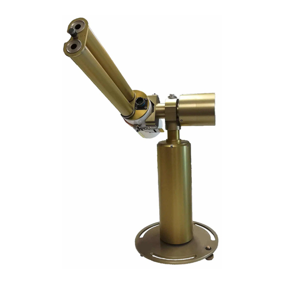
- Page 8 CE318-T Photometer User Operation Manual 1: notch 2: tightening screw 3: alignment hole 4: spot 3. Robot The robot is the component on which the sensor head is attached. Its mechanical design enables it to point on whole directions of the sky on the azimuthal and polar (zenith) angles with a very high accuracy.
- Page 9 CE318-T Photometer User Operation Manual 4. Tripod and tray The tripod is the supplied infrastructure where the protection case and the robot are fixed and that enables the whole system to be stably fixed on the ground. The tray is a part fixed horizontally on the tripod and where the robot will be fixed on.
- Page 10 CE318-T Photometer User Operation Manual The case is the component where the CU and the pair of batteries are placed. The solar panel that powers the system is incorporated in the case.The output plug of the solar panel is a RJ11 connector.
- Page 11 CE318-T Photometer User Operation Manual 7. Sensor head cord The sensor head cord connects the CU and the sensor head. The standard length is 3 meters. One side connector is DB15 (male) type and this other side is Jupiter type with 22 pins (female) Revision 4.3 January 2018...
- Page 12 CE318-T Photometer User Operation Manual 8. Batteries and charger The black batteries supply power to the CU. The battery is 8AH. The YUASA battery is furnished when the satellite transmitter is used. The battery is 24AH. The Mascot 2240 battery charger is used only in case of solar panel breakdown.
- Page 13 The satellite transmitter is useful in remote places where no reliable PC is available. It enables to send the data directly to an appropriate geostationary satellite which has a dedicated transmission channel for the CIMEL photometers. 1: Solar Panel Solartek...
-
Page 14: Sensor Head Types
CE318-T Photometer User Operation Manual 1.3. Sensor head types 5 different sensor head types exist: Standard: It uses 340, 380, 440, 500, 675, 870, 937, 1020 and 1640 nm filters Polarized: A filter wheel containing 3 sets of 3 polarizers operating in infrared (POL1), Ultraviolet (POL2), and visible (POL3) and which are orientated with a 120°... -
Page 15: Data Transmission
CE318-T Photometer User Operation Manual Figure 3: STANDARD type Figure 1: BRDF type Figure 2: SEAPRISM type Figure 4: BRDF 12 filters type Figure 5: POLARISED type 1.4. Data transmission The photometer can use 3 different communication protocols to send its data from the CU. -
Page 16: Installation
CE318-T Photometer User Operation Manual Satellite data transfer using a DCP transmitter module. The proper way to set the module is explained in the Installation chapter. USB link for punctual connections Installation 2.1. Installation site recommendations The site should be chosen carefully in order to comply with the following conditions: ... -
Page 17: Tripod Mounting
CE318-T Photometer User Operation Manual 2.2.2. Tripod mounting The tripod mounting system is designed for easy installation of the photometers in most site conditions. 1. Insert the three photometer tripod feet into the metallic frame. 2. Tight the 3 screws on the tripod feet. -
Page 18: Case Mounting
CE318-T Photometer User Operation Manual 6. Attach the tripod feet to the ground with appropriate screws. Note: Orientate the protection case emplacement South if the location is in the Northern hemisphere or North if the location is in the Southern Hemisphere. -
Page 19: Robot And Sensor Head Mounting
CE318-T Photometer User Operation Manual 9. Put the foam at the bottom of the case and on the sides, place the batteries and the CU as shown on the picture below. 2.2.4. Robot and sensor head mounting 10. Put the screws into white plastic part. - Page 20 CE318-T Photometer User Operation Manual 12. Connect AZ (robot AZimuthal motor), ZN (robot Polar motor), solar panel, and wet sensor and battery wires to the removable terminal block of the CU passing them going through the cable glands of the protection case.
- Page 21 CE318-T Photometer User Operation Manual 14. Set the horizontal robot axis in the East-West direction by manually turning the whole base of the robot. 15. Assemble the collimator to the sensor head front plates by tightening strongly the long central threaded rod using a plier. The notch must face the 4 quadrants lens on the sensor head front plate.
- Page 22 CE318-T Photometer User Operation Manual Note: Watch out that the collimator and the sensor head are completely interdependent. There should be no slack while trying to move the collimator after having tightened it. 16. Strap the sensor head on the V-shaped support of the robot. Two things are to be checked.
- Page 23 CE318-T Photometer User Operation Manual 17. Plug the sensor head cord from the CU to the sensor head passing it through the cap and attaching it to the pig tail. Connect the computer or the transmitter to the DCP input on the removable terminal block via a RS232 to RJ11 cable.
- Page 24 CE318-T Photometer User Operation Manual 18. Level the robot up so that it’s perfectly horizontal by playing on both precision wheels until the spirit level on the top of the robot is centred. This part is a little tricky and may take few trials. Using an additional tubular sprit level may facilitate this step.
- Page 25 CE318-T Photometer User Operation Manual Note: Place the spirit level on the robot V-shaped part after the PARK scenario. It should be perfectly horizontal, if not refer to part 5.2.2. Revision 4.3 January 2018...
- Page 26 CE318-T Photometer User Operation Manual 21. Launch a GoSun scenario in the CU menu. The sensor head is going to point the sun. Polar and Azimuthal values are displayed in degree on the CU screen. After a GOSUN scenario the sun spot may not be centred on the target.
- Page 27 CE318-T Photometer User Operation Manual If not centred on the azimuthal axis, refine the manual positioning of the robot base as done in step 14. (The screws being loosened the base can still be moved). After having done the corrections, repeat steps 20 and 21 to check again the position of the sun spot.
- Page 28 CE318-T Photometer User Operation Manual Important note: watch out that the level didn’t move. If the level moved, go back to step 18 and after repeat step 20, 21, 22. 25. Format the SD card and the flash memory. 26. Set the photometer in automatic mode.
-
Page 29: Communication Protocol Installation And Setup
Plug the RS232 link to the dedicated PC (already done in installation part) Install PhotoGetData on the computer The software is provided on the USB stick or a CD sent with the instrument and can be downloaded on Cimel website. Launch PhotoGetData. In the tools configuration menu: In the communication tab: Choose Serial in the communication type and choose the Port COM associated to... - Page 30 CE318-T Photometer User Operation Manual Note: USB should be used only for punctual data transfer. The backup on the SD card can’t be done when the USB link is plugged. In the data tab: Tick enable the creation of automatic recording, create K8 and/or create ASCII ...
-
Page 31: Usb Communication
2.3.2. USB communication 2.3.2.1. Software configuration The user should install the USB driver provided by Cimel. (see PhotoGet data manual). Plug the USB cable to the dedicated PC. Install PhotoGetData. The software is provided on the USB stick or a CD sent with the instrument and can be downloaded on Cimel website.Launch PhotoGetData. - Page 32 CE318-T Photometer User Operation Manual 2.3.3.1. Operation The user inserts the SIM card into the slot provided in the photometer control box. He should make sure in accordance with the chosen operator that the GPRS coverage is efficient on his field-site.
-
Page 33: Satellite Transmission Installation And Configuration
CE318-T Photometer User Operation Manual USER: Username used to login on the FTP server. Maximum length: 32 characters. Default: “anonymous“. PASS: Password for the username. Maximum length: 32 characters. Default: “guest“. PORT: Communication port used to establish the FTP session communication with the FTP server [1;... - Page 34 CE318-T Photometer User Operation Manual 2.3.4.1. Transmitter and antenna installation 1. Attach the mast support in the ground. 2. Insert the mast into the mast support. 3. Tight the screws to fix properly the mast. Revision 4.3 January 2018...
- Page 35 CE318-T Photometer User Operation Manual 4. Slide the stirrup through the mast until it gets to the end position. 5. Insert the V-shaped part in the stirrup extremities with the mast in between and tight strongly the nuts. 6. Insert the stirrup extremities in the V-shaped part with the tubular metallic part in between to fix it.
- Page 36 CE318-T Photometer User Operation Manual 8. Insert the YAGI antenna support in the stirrups with the tubular metallic part in between. Orientate the support to the right angle on the azimuthal plan. 9. Tight the 4 nuts. 10. Insert the YAGI antenna into its support. Orientate the antenna to the right polar angle.
- Page 37 CE318-T Photometer User Operation Manual 12. Insert the 2 white screws into the V-shaped part. 13. Put the white screws around the mast. 14. Insert the fixing flats into the white screws until it gets in contact with the mast and tight the 2 nuts.
- Page 38 CE318-T Photometer User Operation Manual 17. Repeat step 22 and 23 with the second panel brace. 18. Insert the screws in the solar panel slides. Revision 4.3 January 2018...
- Page 39 CE318-T Photometer User Operation Manual 19. Insert those screws in the panel braces. 20. Tight the bolts to fix the solar panel properly. 21. YAGI antenna assembled. 22. Connect the transmitter RF Output to the antenna with a RG-8 cable (not provided).
- Page 40 CE318-T Photometer User Operation Manual 2.3.4.2. Transmitter configuration with the CU The satellite transmitter configuration is set from the CU menus: Go in the SETTINGS menu and set the following parameters: DCP. Set DCP to On to enable satellite communication ...
-
Page 41: Control Unit Navigation Menu
CE318-T Photometer User Operation Manual DCP offset. It is the time offset from the whole period where the data will be sent. This parameter will be provided by the network administrator. Control Unit navigation menu 3.1. Capacitive key functions The red key is used to exit a menu or to cancel an action. -
Page 42: Scenarios
CE318-T Photometer User Operation Manual 3.4. SCENARIOS The SCENARIO menu varies according to the photometer sensor head option. The table below is lists all scenarios available according to the sensor head used. These scenarios are described in part 4.1. Photometer sensor head option... - Page 43 CE318-T Photometer User Operation Manual GOMOON* CROSS TRACKMOON* CURVECROSS MOON* 3 SUN LTRACK MOON* GOMOON* CROSS MOON* TRACKMOON* 3 MOON* MOON* LTRACK MOON* CROSS MOON* 3 MOON* *: these scenarios are executed only when the moon mode is activated (see part 3.7) The SCENARIO menu allows the manual launch of an individual scenario.
-
Page 44: Measures
CE318-T Photometer User Operation Manual 3.5. MEASURES Sensors included in the CU measure the additional parameters listed below. Values are displayed in real-time and updated every 5 seconds: Battery: Voltage of the external battery. Ibattery: Consumption by the electronic box. -
Page 45: Date
CE318-T Photometer User Operation Manual P. Moon: Period between two Group L scenarios. [2min; 15min]: 3min. Country: Country identification. [0; 255]: 0. District: District identification. [0; 255]: 0. Number: Number identification. [0; 9999]: 0. Latitude: Latitude of the current electronic box. [-90.00°; +90.00°]: 0.0000°. -
Page 46: Cimel
User Operation Manual 3.9. CIMEL Here is a list and description of the parameters in the CIMEL menu: TSV: displays True Solar Time. ROBOT: displays the robot azimuthal and polar mechanical switches values GPS INFO: enter in this menu to enable automatic GPS acquisition. The acquisition starts when the State information is set to “Wait GPS…”... - Page 47 CE318-T Photometer User Operation Manual SUN: The SUN scenario consists in measuring the sun irradiance for all the wavelengths. SUN gains are used and the measurements are done in the following order: Filters used and their sequence (i for InGaAs channel)
- Page 48 CE318-T Photometer User Operation Manual 500 nm AUREOLE 500 nm AUREOLE 550 nm AUREOLE 500 nm AUREOLE 380 nm AUREOLE 380 nm AUREOLE 380 nm AUREOLE 555 nm AUREOLE 1020 nm SKY 340 nm AUREOLE 740 nm AUREOLE 782 nm AUREOLE...
- Page 49 CE318-T Photometer User Operation Manual SKY gain, InGaAs channel SKY CALIBRATE: The SKY CALIBRATE scenario consists in performing 3 SKY and 1 BLACK scenario. HYBRID (Standard, Polarised): Scenario validation in progress. Description is not available yet. ALMU (Standard, BRDF) / ALMUP (Polarised): The ALMUcantar technique consists in measuring the sky radiance in aerosol channels, keeping a constant polar angle equal to the zenith solar angle with varying azimuthal angle.
- Page 50 CE318-T Photometer User Operation Manual Standard Polarized BRDF BRDF 12 filters Filters used and their order in the sequence 1020 nm 1020 nm SKY POL IR 0-1-2-3 1020 nm 1020 nm 1640i nm 1640i nm SKY POL IR 0-1-2-3 1640i nm...
- Page 51 CE318-T Photometer User Operation Manual Head sensor T (°C) Sensor head T (°C) 740 nm 702 nm 714 nm Sensor head T (°C) PP / PPP: The Principal Plan technique also consists in measuring the sky radiance in the aerosol channels. Unlike the almucantar, a constant azimuthal angle is kept with varying polar angle to make measurements.
- Page 52 CE318-T Photometer User Operation Manual Filters used and their order in the sequence Standard Polarized BRDF BRDF 12 filters 1020 nm 1020 nm SKY POL IR 0-1-2-3 1020 nm 1020 nm 1640i nm 1640i nm SKY POL IR 0-1-2-3 1640i nm...
- Page 53 CE318-T Photometer User Operation Manual 702 nm 714 nm Sensor head T (°C) CROSS SUN / MOON: The Cross Sun / Moon scenario consists in measuring sun or moon irradiance in 2 bands for several angles close to the sun / moon, using a cross scheme.
- Page 54 CE318-T Photometer User Operation Manual Filters used and their sequence Standard Polarized BRDF BRDF 12 filters 1020 nm 1020 nm 1020 nm 1020 nm 1640i nm 1640i nm 1640i nm 1640i nm CURVATURE CROSS: Scenario validation in progress. Description not available yet.
-
Page 55: Sunp (Polarised): The Sun Polarised Scenario Consists In Measuring The Sun Directly On All Polarisers With All Filters
CE318-T Photometer User Operation Manual shore platform or on a jetty. Then the field of view is reduced and AHL and AHR enable to set this reduced field of view to only measures the sea radiance. Filters used and their sequence... -
Page 56: Moonp (Polarised): The Moon Polarised Scenario Consists In Measuring The Moon Directly On All Polarisers With All Filters Except 937, 380 And 340Nm
CE318-T Photometer User Operation Manual Filters used and their sequence Polarized 1020 nm SUN POL IR 0-1-2-3 1640i nm SUN POL IR 0-1-2-3 870 nm SUN POL IR 0-1-2-3 675 nm SUN POL VIS 0-1-2-3 440 nm SUN POL VIS 0-1-2-3... -
Page 57: Day And Night Measurement Schedule In Auto Mode
CE318-T Photometer User Operation Manual Group S 3 SUN; ALMU; PP; BRDF; BLACK; Note 1: In bold, measures that are done only with the polarised photometers. By default only HYBP is done. ALMUP and PPP have to be activated in PW on the CU. - Page 58 CE318-T Photometer User Operation Manual Air mass 4.5 77.16° Group A Air mass 4.0 75.52° Group E Air mass 3.8 74.74° Group A Air mass 3.6 73.87° Group A Air mass 3.4 72.89° Group A Air mass 3.2 71.79° Group A Air mass 3.0...
-
Page 59: Brdf And Brdf 12 Filters
CE318-T Photometer User Operation Manual An empty period without any measurements may exist between air mass 1.7 and 9H00 in the morning and between 15H00 and air mass 1.7 in the afternoon. If it is the case, the following scheduler is executed:... -
Page 60: Seaprism
CE318-T Photometer User Operation Manual 4.3.3. SEAPRISM The SEAPRISM photometer executes group P scenario every day from sun air mass 5 in the morning to sun air mass 5 in the evening. The group P scenario automatically starts at every round hour and half hour True Solar Time. - Page 61 CE318-T Photometer User Operation Manual If wet, “wet” is displayed, if not “dry” is displayed. In order to test the sensor if it is not raining, wet it with water and wait around 20s, the value of wetting should go from “dry” to “wet”.
-
Page 62: Corrective Maintenance
CE318-T Photometer User Operation Manual 5.2. Corrective maintenance 5.2.1. Solar panel and wet sensor replacement The wet sensor and the solar panel on the case are already mounted. They might be replaced in case of breakdown. 1. Loosen the 4 nuts. -
Page 63: Robot Levelling Adjustment
CE318-T Photometer User Operation Manual 5.2.2. Robot levelling adjustment After a PARK scenario, even if the spirit level is well-centred, it might happen that the V-shape part of the robot is not perfectly horizontal. You can check with a leveller. - Page 64 CE318-T Photometer User Operation Manual 2. Rotate the robot horizontal axis so that the V-shaped part is perfectly horizontal. Check with the leveller. 3. Tighten the screws and check is the V-shape part is perfectly horizontal after having launched a PARK scenario.
-
Page 65: Flash Memory Formatting
Factory calibration and maintenance 6.1. Sensor head calibration and maintenance Cimel recommends its customers to calibrate the photometers every 12 to 24 months. The calibration consists in a SKY calibration using an integrating sphere and a SUN calibration by inter-comparison or using Langley plots method. -
Page 66: Troubleshooting
CE318-T Photometer User Operation Manual Replacement of transmission belts Full cleaning of transmission gears, greasing of transmission gears and aging. Troubleshooting 7.1. Communication and data transfer is down 7.1.1. Using serial port transfer protocol The possible causes that may interrupt the communication between the PC and the photometer are: ... -
Page 67: Using Satellite Transmitter
User Operation Manual Try another cable. Try another port COM on the acquisition computer if possible If this procedure does not solve the problem, please contact CIMEL technical support. 7.1.2. Using satellite transmitter The possible causes that may interrupt the communication between the photometer and the satellite are: ... - Page 68 If this procedure does not solve the problem, it means that the sensor head cord is probably damaged. Please contact Cimel technical support for any damaged sensor head cord or if the procedure is not solving the problem. Revision 4.3 January 2018...
-
Page 69: Ingaas / Silicon Discrepancy
Procedure to follow: Clean the collimator with dry air or a bottlebrush and make sure that nothing is obstructing the channels. If this procedure does not solve the problem, please contact CIMEL technical support. 7.4. High dark current If the photometer is declared in AERONET network, “high dark current”... -
Page 70: Constant Humidity
CE318-T Photometer User Operation Manual Check all external cables and wires especially the connections. If this procedure does not solve the problem, please contact CIMEL technical support. 7.5. Constant humidity If the photometer is declared in AERONET network, “constant humidity” warning flags can be emitted. -
Page 71: Dissymmetric Almucantar
Go to ROBOT in the CIMEL menu. Look at the sae (switch angle engagement) values for AZ and ZN. These values should be between 70 and 90. If it is not the case please contact CIMEL technical support. 7.7. Dissymmetric Almucantar If the photometer is declare on the AERONET network, dissymmetric almucantar warning flags can be emitted. -
Page 72: Frequently Asked Questions (Faq)
User Operation Manual Check if the battery has no leakage and is powerful enough. If this has not solved the problem, please contact Cimel technical support. Frequently Asked Questions (FAQ) 1. How often should the calibration process be made? The photometer should go through the calibration process every 12 to 24 months. - Page 73 CE318-T Photometer User Operation Manual 6. How to enter it? To enter the network, a request must be sent to AERONET. See AERONET website. 7. What are the first things to do when I notice that the photometer is down?
-
Page 74: Technical Specifications
CE318-T Photometer User Operation Manual Technical specifications 9.1. General Specification value Irradiance precision < 0.1% Field of view 1.3° Minimal scattering angle from the sun 2° Spectral range 340 to 1640 nm Optical filter drift < 1% / year Automated mount... -
Page 75: Dimensional Drawings
CE318-T Photometer User Operation Manual 9.2. Dimensional drawings Revision 4.3 January 2018... - Page 76 CE318-T Photometer User Operation Manual Revision 4.3 January 2018...
- Page 77 CE318-T Photometer User Operation Manual Revision 4.3 January 2018...
- Page 78 CE318-T Photometer User Operation Manual Revision 4.3 January 2018...
- Page 79 CE318-T Photometer User Operation Manual Revision 4.3 January 2018...
- Page 80 CE318-T Photometer User Operation Manual Revision 4.3 January 2018...
- Page 81 CE318-T Photometer User Operation Manual Revision 4.3 January 2018...
- Page 82 CE318-T Photometer User Operation Manual Revision 4.3 January 2018...
-
Page 83: After-Sales Service And Customer Relations
Your email. Optional: Skype and/or Team Viewer address. In term of technical support, Cimel policy is to diagnose issues using remote maintenance. It avoids a long period without the instrument running and it avoids sending back all the material to the factory in most of the cases.
Need help?
Do you have a question about the CE318-T and is the answer not in the manual?
Questions and answers