Sign In
Upload
Manuals
Brands
rotork Manuals
Measuring Instruments
3450 Series
rotork 3450 Series Manuals
Manuals and User Guides for rotork 3450 Series. We have
2
rotork 3450 Series manuals available for free PDF download: Product Manual
rotork 3450 Series Product Manual (103 pages)
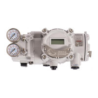
SMART POSITIONER
Brand:
rotork
| Category:
Valve Positioners
| Size: 6 MB
Table of Contents
Table of Contents
2
Introduction
6
General Information for the Users
6
Manufacturer Warranty
6
Explosion Proof Warning & Specific Conditions of Use
7
Product Description
8
General
8
Main Features and Functions
8
Label Description
9
Product Code
15
Product Specification
16
Specification of Digital Input, Digital Output
17
Certifications
17
Parts and Assembly
19
Product Dimension
20
Installation
22
Safety
22
Tools for Installation
23
Linear Positioner Installation
23
Safety
23
Positioner Installation Steps
24
Rotary Positioner Installation
27
Components
27
Rotary Bracket Information
28
Rotary Positioner Installation Steps
29
Connection - Air
31
Safety
31
Supply Pressure Condition
31
Piping Condition
31
Connection - Piping with Actuator
32
Single Acting Actuator
32
Double Acting Actuator
32
Connection - Power
33
Safety
33
Terminal Overview
34
Ground
37
Adjustments
38
A/M Switch Adjustment
38
Variable Orifice Adjustment
38
Maintenance
39
Supply Air
39
Seals
39
Auto Calibration and PCB Operation
40
Warning
40
LCD Display and Buttons
40
LCD Display and Symbols
40
Button and Function
41
Menu Levels
42
Run Mode (RUN)
43
Configuration and Operation
44
Calibration (Calib)
49
Acting Type (SINGLE / Double)
49
Auto Calibration 1 (AUTO 1)
50
Auto Calibration 2 (AUTO 2)
50
Travel Zero (TVL ZERO) and Travel End (TVL End)
51
Manual Operation (man OPER)
52
Manual Operation by Set Position (man SP)
52
Manual Operation by Manipulator Value (man MV)
53
Control Parameters (CTL PARM)
54
Dead Band (Deadband)
54
Forward P Parameter (KP UP) and Reverse P Parameter (KP Dn)
55
Forward Integral Time Parameter (TI UP) and Reverse Integral Time Parameter (TI Dn)
55
Forward D Parameter (Kd UP) and Reverse D Parameter (Kd Dn)
56
GAP Parameter (GAP)
56
GAP P Parameter (GP)
57
GAP I Parameter (GI)
57
GAP D Parameter (Gd)
57
Auto Dead Band Mode (AUTO Db)
58
Performance Mode (PER)
58
Input Configuration (in CFG)
59
Signal Direction (SIG NORM / REVS)
59
Split Range Mode (SPLIT)
60
Custom Split Range Zero (CST ZERO)
60
Custom Split Range End (CST End)
61
Valve Flow Characterization Curves (CHAR)
61
User Set Characterization 5 Points (U5)
62
User Set Characterization 21 Points (U21)
63
Tight Shut Open (TSHUT OP)
64
Target Position Ramp up Rate (RAMP UP) and Target Position Ramp down Rate (RAMP Dn)
66
Digital Input Function (Dif)
67
Digital Input Logic (DI LOGIC)
68
Output Configuration (out CFG)
69
Position Transmitter Direction (PTM NORM / REVS)
69
Position Transmitter Zero / End (PTM ZERO / End)
70
HART Feedback Direction (HT NORM / REVS)
71
Back Calculation (Backcal off / On)
72
Limit Switch Mode (LS Mode Off/ On)
72
Digital Output Function 0 / 1 (Do1 / Do2)
74
Digital Output 1 Logic / Digital Output 2 Logic (Do1 LOGIC HI / Lo, Do2 LOGIC HI / Lo)
75
Analog Output Function (AOF)
76
Analog Output Logic (AO LOGIC lo / HI)
77
Device Configuration (Dev CFG)
78
Action Setting (ACT REVS / Dir)
78
Linear Lever Type (LEVT Std / Adt)
78
Linear Interpolation (ITP off / On)
79
Lock of Parameters (Write Protect, W UNLOCK / LOCK)
79
Actual Position View Mode (View Mode, VI NORM / REVS)
80
Polling Address Setting (POL Addr)
80
Factory Reset (Default off / On)
81
Positioner Self-Test (SELFTEST)
82
Diagnosis Mode (Diagnd)
83
Default Alarm Settings
83
Process Status (PS)
85
Device Status (Ds)
86
View Monitoring Counts (VI CNTS)
88
Diagnostic Limit Configuration (LIMT CFG)
89
Reset Alarm Status (RST ALRM off / On)
90
View Event Log (EVT LOG)
91
Partial Stroke Test Record (View PST Result Record, PST RSLT)
92
PST Configuration (PST CFG)
93
Run PST (PST NOW)
94
Periodic PST Test (PST Schedule, PST Schd off / On)
95
Position Information (INFO)
95
Error Codes During Automatic Calibration
97
Status and Alarm Code
98
Main Software Map
102
Advertisement
rotork 3450 Series Product Manual (70 pages)
Brand:
rotork
| Category:
Measuring Instruments
| Size: 5 MB
Table of Contents
Table of Contents
2
1 Introduction
5
General Information for the Users
5
Manufacturer Warranty
5
Explosion Proof Warning & Specific Conditions of Use
6
2 Product Description
7
General
7
Main Features and Functions
7
Label Description
8
Product Code
14
Product Specification
15
Certifications
16
Parts and Assembly
18
Product Dimension
19
3 Installation
21
Safety
21
Tools for Installation
22
Linear Positioner Installation
22
Safety
22
Positioner Installation Steps
23
Rotary Positioner Installation
26
Components
26
Rotary Bracket Information
27
Rotary Positioner Installation Steps
28
4 Connection - Air
30
Safety
30
Supply Pressure Condition
30
Piping Condition
30
Connection - Piping with Actuator
31
Single Acting Actuator
31
Double Acting Actuator
31
5 Connection - Power
32
Safety
32
Terminal Overview
33
Input Signal Terminal
33
Feedback Signal Terminal
34
Limit Switch Terminal
34
Ground
35
6 Adjustments
36
Limit Switch Adjustment
36
A/M Switch Adjustment
37
Variable Orifice Adjustment
37
7 Maintenance
38
Supply Air
38
Seals
38
8 Auto Calibration and PCB Operation
39
Warning
39
Button Description
39
Run Mode (RUN)
39
Auto Calibration Mode (AUTO CAL)
40
AUTO1 Calibration (AUTO1)
40
AUTO2 Calibration (AUTO2)
41
AUTO 3 Calibration (AUTO 3)
41
AUTO HF Calibration (AUTO HF)
41
Manual Mode (MANUAL)
42
Parameter Mode (PARAM)
42
Dead-Zone (Deadzone, %)
43
P Value (KP)
43
I Value (KI)
44
D Value (Kd)
44
P_ (KP_), I_(KI_), D_ (Kd_) Values
44
KF up Value (KFUP)
45
KF down Value (Kfdn)
45
Control Mode (CTRL)
46
Hand Calibration Mode (HAND CAL)
47
Zero-Point (PV ZERO) and End-Point (PV END) for Valves
47
Zero-Point (TR ZERO) and End-Point (TR END) for Transmitter
48
Normal / Reverse Feedback Signal (TR NORM / REVS)
49
Normal / Reverse HART Signal (HT NORM / REVS)
49
Valve Mode (VALVE)
50
Acting Adjustment (ACT RA / Da)
50
Interpolation Mode (ITP ON/OFF, ITP USER SET)
50
Acting Type (SINGLE / Double)
50
Lever Type (Std / Adt)
50
Valve Flow Characteristic Adjustment (CHAR)
51
User Defining Flow Characteristics (USER SET)
52
Tight Shut Open (TSHUT OP)
54
Tight Shut Close (TSHUT CL)
54
Split Range Mode (SPLIT)
55
Custom Zero Setting Mode of Split Range (CST ZERO)
55
Custom End Setting Mode of Split Range (CST End)
56
Diagnostic (Diagno)
58
PST Introduction
58
PST Mode (PST)
58
PST Configuration (PST CFG)
58
PST Result (PST RSLT)
58
View Mode (VIEW)
64
9 Error and Warning Code
66
Error Code Which Is Displayed During Auto Calibration
66
Error Code Which Is Displayed While Using the Product
67
Error Code Which Can be Checked from View Mode
67
Warning Code Which Can be Checked from View Mode
68
10 Main Software Map
69
Advertisement
Related Products
rotork SPI 1
rotork SPI 2
rotork SPI 3
rotork SPI 4
rotork SPI Series
rotork YT-3400
rotork YT-3450
rotork Categories
Controller
Valve Positioners
Industrial Equipment
Control Unit
Control Systems
More rotork Manuals
Login
Sign In
OR
Sign in with Facebook
Sign in with Google
Upload manual
Upload from disk
Upload from URL