
Related Manuals for rotork YT-3400


Summarization of Contents
1 Introduction
1.1 General User Information
Provides general information and safety guidelines for users of Rotork YTC Limited products.
1.2 Manufacturer Warranty Details
Details the terms and conditions of the manufacturer's warranty for the product.
2 Product Description
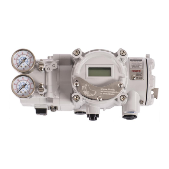
2.1 Product Overview
Provides a general overview of the smart positioner's function and capabilities.
2.2 Key Features and Functions
Lists and describes the key features and operational functions of the smart positioner.
2.3 Product Label Information
Explains the information presented on the product's identification label.
2.8 Product Dimensions
2.8.1 YT-3400 Dimensions
Shows dimensional drawings and measurements for the YT-3400 model.
2.8.2 YT-3450 Dimensions
Shows dimensional drawings and measurements for the YT-3450 model.
3 Installation Guide
3.1 Installation Safety Precautions
Highlights critical safety precautions to be followed during the installation process.
3.2 Required Installation Tools
Lists the necessary tools required for the installation of the positioner.
3.3 Linear Positioner Installation
Details installation steps for linear motion valves, including safety considerations.
3.4 Rotary Positioner Installation
3.4.1 Rotary Installation Components
Lists the components required for the rotary positioner installation.
3.4.2 Rotary Bracket Information
Explains adjusting and using rotary brackets for different actuator stem heights.
3.4.3 Rotary Positioner Installation Steps
Provides step-by-step instructions for installing the rotary positioner.
4 Air Connection
4.1 Air Connection Safety
Highlights safety precautions for connecting air supply to the positioner.
4.2 Supply Pressure Conditions
Specifies the required conditions for the air supply pressure.
4.3 Piping Conditions
Details the requirements for piping and connections for air supply.
4.4 Piping Connections to Actuator
4.4.1 Single Acting Actuator Connection
Explains the air piping connection for single acting actuators.
4.4.2 Double Acting Actuator Connection
Explains the air piping connection for double acting actuators.
5 Power Connection
5.1 Power Connection Safety
Outlines critical safety measures for connecting power to the positioner.
5.2 Terminal Overview
Provides a diagram and explanation of the positioner's terminal connections.
5.2.1 Input Signal Terminal Wiring
Details how to connect the input signal wires to the terminal block.
5.2.2 Feedback Signal Terminal Wiring
Explains how to connect the feedback signal wires to the terminal block.
5.2.3 Limit Switch Terminal Wiring
Details the connection procedure for limit switch wiring.
5.2.4 Ground Connection Procedure
Explains the correct procedure for grounding the positioner for safety.
6 Adjustments
6.1 Limit Switch Adjustment
Describes adjusting limit switches for valve end-point and zero-point settings.
6.2 A/M Switch Adjustment
Explains adjusting the Auto/Manual switch for controlling the actuator.
6.3 Variable Orifice Adjustment
Details adjusting the variable orifice to prevent hunting and optimize flow.
7 Maintenance
7.1 Supply Air Quality
Emphasizes clean and dry air supply for proper positioner function.
7.2 Seal Inspection and Replacement
Recommends annual inspection and replacement of positioner seals if damaged.
8 Auto Calibration and PCB Operation
8.1 Warning Before Calibration
Provides a critical warning to isolate the valve before performing auto calibration.
8.2 Button Description
Explains the function of the four buttons used for operating the positioner.
8.3 Run Mode Operation
Describes the 'RUN' mode, its displays, and navigation.
8.4 Auto Calibration Modes (AUTO CAL)
8.4.1 AUTO1 Calibration Process
Details steps for AUTO1 calibration, adjusting zero and end points.
8.4.2 AUTO2 Calibration Process
Describes AUTO2 calibration, adjusting all parameters for initial setup.
8.4.3 AUTO 3 Calibration Process
Explains AUTO 3 calibration, including KF function for long dead time.
8.4.4 AUTO HF Calibration Process
Details AUTO HF calibration for valves with high friction levels.
8.6 Parameter Mode (PARAM)
8.6.1 Dead-Zone Adjustment
Explains adjusting Dead-Zone parameter to stabilize valve operation.
8.6.2 P Value (KP) Adjustment
Explains P value (KP) effect on response speed and stability.
8.6.3 I Value (KI) Adjustment
Details I value (KI) impact on hunting and slow movement.
8.6.4 D Value (Kd) Adjustment
Explains D value (Kd) effect on linearity and dynamics.
8.6.5 PID Value Activation Rules
Clarifies when P, I, and D values activate based on error percentage.
8.6.6 KF Up Value (KFUP) Adjustment
Describes KF Up control for reducing dead time by correcting valve friction.
8.6.7 KF Down Value (KFdN) Adjustment
Explains KF Down control for reducing dead time with high valve friction.
8.6.8 Control Mode (CTRL) Selection
Details selecting control modes: FAST, NORMAL, STABLE, HIGH FRICTION.
8.7 Hand Calibration Mode (HAND CAL)
8.7.1 Valve Zero and End Point Adjustment
Details adjusting valve zero and end points using PV ZERO and PV END.
8.7.2 Transmitter Zero and End Point Adjustment
Explains adjusting transmitter zero (4mA) and end point (20mA) for feedback.
8.7.3 Feedback Signal Mode (TR NORM/REVS)
Describes changing the feedback signal to normal or reverse.
8.7.4 HART Signal Mode (HT NORM/REVS)
Explains changing HART communication signal to normal or reverse.
8.8 Valve Mode Operation
8.8.1 Acting Adjustment (ACT RA/DA)
Details adjusting the actuator's acting type (Direct/Reverse Action).
8.8.2 Valve Flow Characteristic Adjustment (CHAR)
Explains setting valve flow characteristics: linear, user, quick open, equal percentage.
8.8.3 User Defined Flow Characteristics (USER SET)
Guides on creating custom flow characteristics using 5 or 18 points.
8.8.4 Tight Shut Open (TSHUT OP)
Explains setting tight shut open percentage to prevent leakage.
8.8.5 Tight Shut Close (TSHUT CL)
Details setting tight shut close percentage to prevent leakage.
8.8.6 Split Range Mode (SPLIT)
Describes operating valve with split range control (4-12mA or 12-20mA).
8.8.7 Custom Zero Setting for Split Range (CST ZERO)
Guides on changing zero point for split range control from 4mA.
8.8.8 Custom End Setting for Split Range (CST END)
Details changing end point for split range control up to 20mA.
8.8.9 Interpolation Mode (ITP ON/OFF)
Explains managing interpolation mode for accuracy in linear to rotary motion conversion.
8.8.10 Acting Type (SINGLE/DOUBLE)
Displays or changes the actuator's current acting type.
8.8.11 Lever Type (STd/AdT)
Displays or changes the current lever type (standard or adapter).
8.9 Diagnostic Functions (DIAGNO)
8.9.1 PST Introduction
Explains Partial Stroke Test (PST) for testing valve failure percentage.
8.9.2 PST Mode Selection
Details selecting PST modes (OFF, NOW, SCHD) for running the test.
8.9.3 PST Configuration (PST CFG)
Guides on checking and configuring PST parameter values.
8.9.3.1 Start Position (START PO) Configuration
Explains setting the start position for PST initiation.
8.9.3.2 Target 1 (TARGET 1) Configuration
Guides on setting the first target position for PST.
8.9.3.3 Target 2 (TARGET 2) Configuration
Details setting the second target position for PST.
8.9.3.4 Interval (INTERVAL) Configuration
Explains setting the interval time between PST tests.
8.9.3.5 Tolerance (TOL) Configuration
Guides on setting the tolerance level for the PST start position.
8.9.3.6 Limit Time (LIMIT TM) Configuration
Details setting the stroke time limit for PST.
8.9.3.7 Latency (LATENCY) Configuration
Explains setting latency for movements after valve actuation.
8.9.4 PST Results (PST RSLT)
Describes how PST results and error messages are recorded and displayed.
8.10 View Mode (VIEW)
View Mode Data Displays
Details BIAS values, time/operation counts, VM modes, error codes, service, and temperature info.
9 Error and Warning Codes
9.1 Auto Calibration Error Codes
Lists and describes error codes specific to the auto calibration process.
9.2 Product Usage Error Codes
Details error codes that appear during the normal use of the product.
9.3 View Mode Error Code Checking
Explains how to check error codes via the View mode.
9.4 View Mode Warning Code Checking
Lists and describes warning codes that can be checked from View mode.
Need help?
Do you have a question about the YT-3400 and is the answer not in the manual?
Questions and answers