Table of Contents
Advertisement
Quick Links
This manual contains important safety informations about
installation and use of this equipment. Ignoring this informations
could result in injuries or damages.
It is strictly forbidden to use this equipment with radioactive
chemicals!
OPERATING MANUAL FOR
"DIN DIGITAL CL" CONTROLLER
Read carefully!
ENGLISH Version
1
R1-09-04
Advertisement
Table of Contents

Subscribe to Our Youtube Channel
Related Manuals for Emec DIN Digital CL


Summary of Contents for Emec DIN Digital CL
- Page 1 This manual contains important safety informations about installation and use of this equipment. Ignoring this informations could result in injuries or damages. It is strictly forbidden to use this equipment with radioactive chemicals! OPERATING MANUAL FOR “DIN DIGITAL CL” CONTROLLER Read carefully! ENGLISH Version R1-09-04...
- Page 2 NORME CE EC RULES(STANDARD EC) NORMAS DE LA CE ⎬ Direttiva Bassa Tensione 2014/35/UE Low Voltage Directive Directiva de baja tensión ⎬ Direttiva EMC Compatibilità Elettromagnetica EMC electromagnetic compatibility directive 2014/30/UE EMC directiva de compatibilidad electromagnética GENERAL SAFETY GUIDELINES Danger! In emergencies the instrument should be switched off immediately! Disconnect the power cable from the power supply! When installing always observe local regulations!
-
Page 3: Table Of Contents
Index INDEX GENERAL DESCRIPTION ..............4 CONTROL PANEL ................4 ELECTRICAL WIRINGS ..............5 VIEW ON MENU ................6 SETTING SETPOINTS: 1)SETPN ............6 Out mA ..................7 CALIBRATION: 2)CALIB ..............8 DELAY: 3) Delay ................9 RESERVED: 4) Reserv ..............9 PASSWORD SETUP: 1) New Pw ............ -
Page 4: General Description
Introduction GENERAL DESCRIPTION “DIN Digital CL” measures and controls chlorine in industrial process. It is possible to set two ON/OFF setpoints and a current ÷ ÷ signal for connecting a chart recorder or a metering pump. It is possible to set the current output on 0 20 or 4 20 mA. -
Page 5: Electrical Wirings
Installation ELECTRICAL WIRINGS: 1 2 3 4 5 6 7 8 9 10 11 12 13 14 15 16 1 - 2: Power Supply (230VAC* or 115VAC* or 24VAC*). 3-4: Setpoint 1 output - free contact. 5-6: Setpoint 2 output - free contact. 7-8: Chlorine Probe mod. -
Page 6: View On Menu
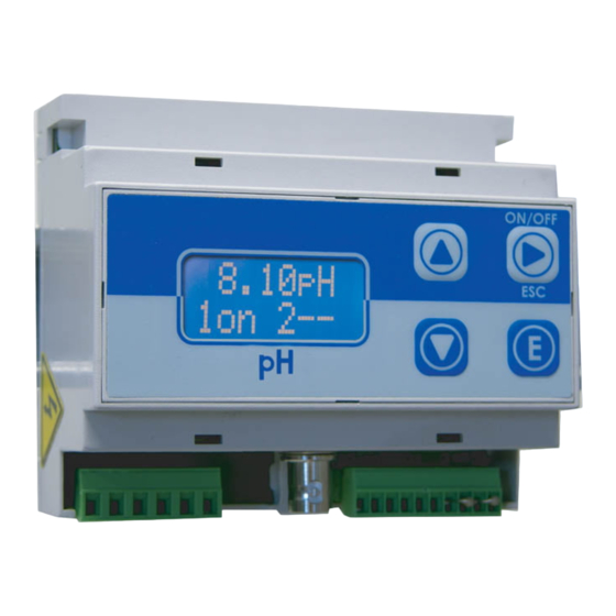
Installation VIEW ON MENU Make connections and plug the instrument. Instrument’s version message on display confirms that the instrument is on. The display shows also the probe reading status and if setpoints are active. Press “E” for about 4 seconds to enter into setup menu. Note: During setup the instrument is in “Stand-by”... -
Page 7: Out Ma
SETUP The instrument shows: 1a) ->OFF 1.00Cl Pressing twice “RIGHT” key the display will show: 1b) ->ON 0.00Cl “1a)” and “1b)” are working range values. Every range is set by a value that operates relay output. Using default values, the setpoint 1 will drive a pump that will increase the chlorine value. -
Page 8: Calibration: 2)Calib
SETUP CALIBRATION: 2)CALIB Choose “CALIB” from main menu. Display shows: Calib 1)Zero Press “UP” key. Display shows: Calib 2) Slope Zero calibration. When display shows “1) Zero” press “E” to enter into zero calbration procedure. Display shows: R 1.00Cl C 0.00Cl To calibrate it , if you are using an ECL4-6-7 probe, close water’s flow and wait for some minutes. -
Page 9: Delay: 3) Delay
SETUP DELAY: 3) Delay t’s possible to set an activation delay for each output when the instrument reaches the setpoint values. Default value is set to 0. Select “DELAY” from “SETUP” menu. The instrument will show: OUT1 10 Sec. Press “RIGHT” key. The instrument will show: OUT2 5 Sec. -
Page 10: Password Setup: 1) New Pw
PARAM PASSWORD SETUP: 1) New Pw To avoid undesired access to the instrument a 4 number password may be set. Using “UP” or “DOWN” keys, from “Param” menu choose “1) New Pw”, press “E” to confirm. The display shows: NEW PW ->... -
Page 11: Manual Working Mode: 3) Serv
SERV. MANUAL WORKING MODE: 3) Serv. This function allows to manual control the external relays contact (SP1 / SP2). The display will show 1 or 2 to show the selected setpoint/output. The output status can be set “ON” or “OFF” using “UP” key for SP1 and “DOWN”... - Page 12 Disposal of end-of-life equipment by users This symbol warns you not to dispose of the product with normal waste. Respect human health and the environment by giving the discarded equipment to a designated collection center for the recycling of electronic and electrical equipment. For more information visit the online site.
Need help?
Do you have a question about the DIN Digital CL and is the answer not in the manual?
Questions and answers