Table of Contents
Advertisement
This manual contains safety information that if ignored
can endanger life or result in serious injury. They are
indicated by this icon.
Keep the instrument protected from sun and water.
Avoid water splashes.
OPERATING INSTRUCTIONS F O R
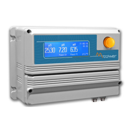
"MTOWER PLUS" INSTRUMENT
CD/PH/RH Version
Read Carefully !
ENGLISH Version
1
R12-01-18
Advertisement
Table of Contents

Related Manuals for Emec MTOWER PLUS Series


Summary of Contents for Emec MTOWER PLUS Series
- Page 1 This manual contains safety information that if ignored can endanger life or result in serious injury. They are indicated by this icon. Keep the instrument protected from sun and water. Avoid water splashes. OPERATING INSTRUCTIONS F O R “MTOWER PLUS” INSTRUMENT CD/PH/RH Version Read Carefully ! ENGLISH Version...
- Page 2 NORME CE EC RULES(STANDARD EC) NORMAS DE LA CE ⎬ Direttiva Bassa Tensione 2014/35/UE Low Voltage Directive Directiva de baja tensión ⎬ Direttiva EMC Compatibilità Elettromagnetica 2014/30/UE EMC electromagnetic compatibility directive EMC directiva de compatibilidad electromagnética GENERAL SAFETY GUIDELINES Danger! In emergencies the instrument should be switched off immediately! Disconnect the power cable from the power supply! When installing always observe local regulations!
- Page 3 Introduction. The “MTOWER PLUS” is a fully featured cooling towers controller with two-way biocide options and inhibitor / bleed control.Cooling towers are heat removal devices used to transfer process waste heat to the atmosphere. Cooling towers may either use the evaporation of water to remove process heat and cool the working fluid to near the wet-bulb air temperature or rely solely on air to cool the working fluid to near the dry-bulb air temperature.
- Page 4 Mainboard Connections. Unplug instrument from main power supply then perform connections to probes and / or selected outputs by following the above picture. For easy understanding board has been divided into two parts: Power connections and I/O connections. CD Module Module Module L 1 2 3 4 5 6...
- Page 5 I/O Connections: STANDBY OUT (1-6) PROPORTIONAL OUT (7-12) 1: - D1 mV (Biocide1) 3: - Biocide2 5: - Pre-biocide1 7: - (Cl) 9: - pH 11: - Inhibitor Standby / Proportional Outputs: 2 + D1 mV (Biocide1) 4: + Biocide2 6: + Pre-biocide1 8: + (Cl) 10: + pH 12: + Inhibitor 13: Common mA outputs (500 Ohm max resistive load): 14: mA output 1 (conductivity)
- Page 6 Cooling tower basic knowledge. What is a (wet, atmospheric) cooling tower? A cooling tower is a heat rejection device, which extracts waste heat to the atmosphere though the cooling of a water stream to a lower temperature. The type of heat rejection in a cooling tower is termed “evaporative” in that it allows a small portion of the water being cooled to evaporate into a moving air stream to provide significant cooling to the rest of that water stream.
- Page 7 Cooling tower basic knowledge. If cooled water is returned from the cooling tower to be reused, some water must be added to replace, or make-up, the portion of the flow that evaporates. Because evaporation consists of pure water, the concentration of dissolved minerals and other solids in circulating water will tend to increase unless some means of dissolved-solids control, such as blow- down, is provided.
- Page 8 “MTOWER PLUS” basic treatments. “MTOWER PLUS” basically operates three main treatments to grant cooling efficiency: inhibitor, bleed and biocide. What is the purpose of inhibitor ? Inhibitor is a chemical compound that, when added to water, decreases the corrosion rate of a metal or an alloy. It prevents cooling tower plant to mantain hoses efficiency in water circulating system.
- Page 9 “MTOWER PLUS” main screen. Local Date Conductivity reading pH reading ORP reading Local Time LAN Connected - Connected to ERMES LAN Cable disconnected Connection Status LAN Connected - Not connected to ERMES USB pen-drive connected Alarm status Plant temperature Outputs status Conductivity status “MTOWER PLUS”...
- Page 10 “MTOWER PLUS” status screen. From main screen rotate wheel (one click - one menu) clockwise for more information about instrument functioning. For more information rotate the wheel clockwise. The instrument will show: “Status Output”, “Status Totalizer”, “Status Level”, “Status Alarm”, “Status Biocide”, SERVICE (for ERMES communication). Status Output PreBiocide 1 or 2 : Pre Biocide 1 or 2 status Biocide 1 or 2 : Biocide 1 or 2 status...
- Page 11 “MTOWER PLUS” basic settings. Basic settings are: PASSCODEs, Time & Date, International Units. Standard settings are: Probes calibration and operating modes (bleed - inhibitor - biocide). Advanced settings are: Flow meter, Alarm and Option menu. All these three settings must be set in order to properly operate the instrument. PASSCODE for “Setup”...
- Page 12 Time & Date setup. To grant access into “Setup” menu press the wheel from main screen, choose “Setup” and enter the PASSCODE. Move on “CLOCK” and press the wheel. To end procedure move cursor on “EXIT” and press wheel to proceed to “Save” request screen. Move wheel on “YES” to save or “NO”...
- Page 13 Units setup. To grant access into “Setup” menu press the wheel from main screen, choose “Setup” and enter the PASSCODE. Move on “UNITS” and press the wheel. Once into submenu press wheel twice on “UNITS” and rotate to choose between “US” unit standard or “IS” international unit standard.
- Page 14 “MTOWER PLUS” standard settings. Standard settings are: Probes calibration and operating modes (bleed - inhibitor - biocide). PASSCODE for “Probe” menu access. To grant access into “Probe” menu press the wheel from main screen, choose “Setup” and enter the PASSCODE. If this is the first time here then the PASSCODE is 0000 (factory preset).
- Page 15 TE & CA Conductivity measurements are temperature dependent. The degree to which temperature affects conductivity varies from solution to solution and can be calculated using the following formula: C25 = C / {1+[a/100(t-25)]} where: C25 = slution conductivity at 25°C, C = conductivity at operating temperature, a = temperature coefficient of solution %/°C.
- Page 16 “Calibration pH” menu. pH calibration procedure involves two calibration points and it requires two buffer solutions. Default buffer solutions are pH 4.00 and pH 7.00. pH reading value can be also 30°C temperature compensated from “CA” field. From “Probe” menu choose “Calibration pH”. In the following example instrument will calibrate pH using default buffer solutions values.
- Page 17 “Calibration pH” menu. Calib 2nd Point. Move wheel on “P2” then press wheel to enter into second point calibration submenu. Prepare 4.00pH buffer solution and dip probe’s sensor on it. Wait until reading value is stable and according to buffer solution value move wheel until it is the same on display (“Cal.
- Page 18 “Calibration pH” menu. TE & CA pH measurements are temperature dependent. The degree to which temperature affects conductivity varies from solution to solution and can be calculated using the following graphic. “MTOWER plus” has either fixed or adjustable automatic temperature compensation referenced to a standard temperature of 25°C.
- Page 19 “Calibration mV” menu. ORP calibration procedure involves one calibration point and it requires a buffer solution. Default buffer solution should be near working value. From “Probe” menu choose “Calibration mV”. In the following example instrument will calibrate ORP using default buffer solutions values. Note: this procedure assumes that instrument is correctly configured and a working ORP probe connected.
- Page 20 “Calibration mV” menu. ORP calibration procedure involves probe’s selection with one point (P1) calibration. From “Menu Calibration” choose “ORP probe”. Note: This procedure assumes that instrument is correctly configured and a working ORP probe connected and installed on system. Measurement must be performed using plant water. Otherwise unattended results might occurr.
- Page 21 “Calibration Temp” menu. To calibrate probe’s temperature enter into “Calibration Temp” menu. A professioanl thermometer is required to obtain a reliable calibration. From “Menu Calibration” choose “Calibration Temp”. Note: This procedure assumes that instrument is correctly installed and configured, connected to a working probe.
- Page 22 “Inhibitor” menu. Inhibitor function can operate in 5 feeding modes. Press wheel and rotate to choose most suitable mode. “WM PPM” submenu can be edited within “L/h” or “cc/st”. Choose Feed & Bleed. Edit Once Bleed mode has been set, the operating time for feeding procedure will be the same as for bleeding.Before setting this mode first configure “Bleed Menu”...
- Page 23 “Biocide 1” and “Biocide 2” menu. Usually two types of chemicals (e.g.: chlorine based chemical and bromine based chemical) are used to obtain best results in killing dangerous microorganisms. Use “Biocide 1” and “Biocide 2” menus to configure these tasks. Parameters to set are the same for both menus.
- Page 24 “Bleed” menu. A method for controlling the amount and concentration of make-up water and chemicals introduced into the recirculating water of a cooling tower system. A float operated make-up valve controls the addition of make-up water to the tower. As make-up water is added to the tower a vacuum is produced at an injector valve which draws chemicals from a chemical holding tank into the make-up water, thereby allowing precise control of the chemical concentration in the make-up liquid.
- Page 25 “Set-Point ORP menu” working modes For “Digital D1” output, setpoint can be set between On/Off mode, PWM mode or disabled (OFF). For “Proportional P1” output (blocks 7 and 8), setpoint can be set using Proportional mode or disabled (OFF). Both options can be operate as “Timer Biocide 1” (mV channel operates within Biocide 1 set time) or “Constant” (three cannels are all independent).
- Page 26 “Set-Point ORP” (PWM) mode - Digital D1 This mode is valid for “Digital D1” output. Pulse-width modulation (PWM) of a signal or power source involves the modulation of its duty cycle, to either convey information over a communications channel or control the amount of power sent to a load. This mode works over a settable (0 to 100 seconds) time to switch on or off selected output.
- Page 27 “Set-Point ORP” - Proportional P1 This mode is valid for “Proportional P1” output (blocks 7 and 8). Proportional mode set the instrument to operate using a calculated percentage between two set values that enable or disable the ORP pump. To use this mode move cursor on “Proportional P1”. Press the wheel and select it. PROPORTIONAL MODE between 700(0 P/m) and 680 (180 P/m).
- Page 28 “Set-Point pH menu” working modes For “Digital D1” output, setpoint can be set between On/Off mode, PWM mode or disabled (OFF). For “Proportional P1” output (blocks 9 and 10), setpoint can be set using Proportional mode or disabled (OFF). “Set-Point pH” (on/off) mode ALKALI This mode is valid for “Digital D1”...
- Page 29 “Set-Point pH” (on/off) mode ACID This mode is valid for “Digital D1” output. ON/OFF mode while dosing ACID Set pH value at 7.00 OFF and 7.10 ON. Set Pulse Speed per minute (strokes per minute) based on dosing device capabilities. Instrument will leave the pH pump active until reading value will decrease up to 7.00pH At 7.00pH the pH pump will be disabled until reading value will increase up to 7.10pH.
- Page 30 “Set-Point pH” (PWM) This mode is valid for “Digital D1” output. Pulse-width modulation (PWM) of a signal or power source involves the modulation of its duty cycle, to either convey information over a communications channel or control the amount of power sent to a load.
- Page 31 “Set-Point pH” (Proportional) This mode is valid for “Proportional P1” output (blocks 9 and 10). Proportional mode set the instrument to operate using a calculated percentage between two set values that enable or disable the pH pump. To use this mode move cursor on “Proportional P1”. Press the wheel and select it. PROPORTIONAL mode between 7pH(0 P/m) and 8pH (180 P/m).
- Page 32 “MTOWER PLUS” advanced settings. Advanced settings are: Flow meter, Alarm and Option menu. “Flow meter” menu. This menu allows to configure: totalizer for water meter input , totalizer for water meter bleed, working mode and counters reset. WMI: Main water input totalizer (not editable) WMB: Bleed water input totalizer (not editable) FM Unit: L/P (liters per pulses) or P/L (pulses per liters) RST TOT : reset both WMI and WMB counters...
- Page 33 “Alarm” menu. This menu allows to enable / disable / set all system alarms and related outputs. LOC: “LOW CONDUCTIVITY” alarm. LPH: “LOW pH” alarm. LMV: “LOW ORP” alarm. OFF: alarm disabled ABS: (absolute) alarm on set value* TRK: (track) alarm on bleed setpoint minus track value* Track alarm (TRK) e.g.: Bleed setpoint is set to 4000 and track alarm is set to 1000.
- Page 34 “Options” menu. Press wheel and rotate to choose. TAU: if probes reading values are displayed too fast increase TAU value to stabilize them. Default value is 03. Maximum value is 30. Coeff Temp: Temperature compensation. Minimum value is 0% (disabled), maximum value is 5%. See page 15 for more info.
- Page 35 “Manual” menu. This menu allows to manually operate all outputs. Move wheel on related output, press wheel two times to enable (ON) and press wheel one more time to disable (OFF) selected output. Press one time again to re-enable (ON) output and so on.
- Page 36 Appendix A - Conductivity Probe Module. Located in there are four connectors that can be used to install probe modules. Modules come upperside of mainboard pre-installed upon request. Identify installed modules to correctly connect probes. ECDS IND PT PROBE Connect probe as follows: Connect 4 probe wires to MDIND module as follow: Block n.1 :Shield Block n.2 : Black (probe)
- Page 37 Appendix B - Dimensions ENVIRONMENT ENCLOSURE IP65 enclosure (NEMA4x) MTOWER control instruments are ma- -10°C ÷ 50°C (14°F ÷ 122°F) nufactured in ABS housing to ensure 0÷95% (non condensing) relative humidity protection against aggressive chemi- cals and tough environment.
- Page 38 Appendix C - Communication “RS485” menu. Prior to install the instrument into an RS485 local system a unique ID NUMBER (from 1 to 30) and ID NAME (station name) must be set. Rotate wheel and edit fields. If ID number has already assigned an error message will follow after ID Check (move cursor on CHECK and press wheel).
- Page 39 “TCP/IP” menu. The instrument can be remotely operated using a standard ethernet connection (sold as option). A static or dynamic IP address and a CAT5 ethernet cable is required. According to your network capacity connection speed is 10/100Mbps. To obtain a valid IP address and subnet mask contact your net administrator. Enter parameters and move cursor on “SAVE”...
- Page 40 “GPRS” menu. Instrument can be remotely operated using an embedded standard GPRS modem (sold as option). In order to activate this service please ensure that the following steps are correctly completed: - Make certain the antenna location is not shielded by metal objects or near sources of electrical ‘noise’. - Make certain the distance from the antenna to the “MTOWER”...
- Page 41 “LOG USB” Module Located under mainboard cover there is a four pins connector that can be used to install “USB data log module” or “SMS module”. Modules come pre-installed upon request and may appear different as shown (different configurations). “USB data log module” records instrument activities. These information can be permanently stored into a standard USB pendrive.
- Page 42 Appendix D - MODBUS Setup Modbus is a serial communications protocol originally published by Modicon (now Schneider Electric) in 1979 for use with its programmable logic controllers (PLCs). Simple and robust, it has since become a de facto standard communication protocol, and it is now a commonly available means of connecting industrial electronic devices. From main menu select SETUP then MODBUS to access the options.
- Page 43 Appendix C - Motorized valve connection...
- Page 44 Addendum “Water Meter” on mA module Enter into “Water Meter” menu to setup Flow Meter configuration type, see total amount of liters passed through water meter, reset totalizer and setup a timeout alarm for no water flow. The alarm will be notified into main screen and water meter status (see page 6).
- Page 45 Appendix - WIFI Connection Within Communication Menu choose “WIFI” to bring wireless sub-menu. Wait until desired wireless network appears, move wheel on it then click. Enter WEP / WPA / WPA2 password (if required) and wait until connection has been estabilished and WiFi signal strength appears.
- Page 47 INDEX. page 3 INTRODUCTION The wheel page 3 page 4 MAINBOARD CONNECTIONS page 6 COOLING TOWER BASICS KNOWLEDGE page 8 “MTOWER PLUS” BASIC TREATMENTS “MTOWER PLUS” main screen page 9 “MTOWER PLUS” operating status messages page 9 “MTOWER PLUS” status screen page 10 page 11 “MTOWER PLUS”...
- Page 48 When dismantling this instrument please separate material types and send them according to local recycling disposal requirements. We appreciate your efforts in supporting your local Recycle Environmental Program. Working together we’ll form an active union to assure the world’s invaluable resources are conserved.
Need help?
Do you have a question about the MTOWER PLUS Series and is the answer not in the manual?
Questions and answers