Advertisement

This manual contains safety information that if ignored can
endanger life or result in serious injury. They are indicated
by this icon.
Keep the controller protected from sun and water.
Avoid water splashes.
OPERATING INSTRUCTIONS FOR
"JA SERIES" / "JA SERIES PRO" CONTROLLERS
Read Carefully !
ENGLISH Version
1
R19-07-19

Advertisement

Table of Contents
loading
Need help?

Need help?

Do you have a question about the JA Series and is the answer not in the manual?

Questions and answers

Summary of Contents for Emec JA Series

  • Page 1 They are indicated by this icon. Keep the controller protected from sun and water. Avoid water splashes. OPERATING INSTRUCTIONS FOR “JA SERIES” / “JA SERIES PRO” CONTROLLERS Read Carefully ! ENGLISH Version R19-07-19...
  • Page 2 NORME CE EC RULES(STANDARD EC) NORMAS DE LA CE ⎬ Direttiva Bassa Tensione 2014/35/UE Low Voltage Directive Directiva de baja tensión ⎬ Direttiva EMC Compatibilità Elettromagnetica 2014/30/UE EMC electromagnetic compatibility directive EMC directiva de compatibilidad electromagnética GENERAL SAFETY GUIDELINES Danger! In emergencies the controller should be switched off immediately! Disconnect the power cable from the power supply! When installing always observe local regulations!
  • Page 3: Introduction

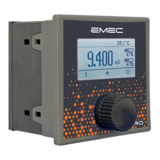
    Some functions are available for PRO model only (see page 25) The wheel JA SERIES has a wheel that must be used to control the controller. Wheel can be rotated in both directions to scroll over the menus and / or pressed to confirm highlighted selection / value.
  • Page 4: Board Connections

    Mainboard Connections JACD and JACD PRO series Unplug controller from main power supply then perform connections by following the picture below. L1 N2 3 4 5 6 7 8 9 10 11 12 13 14 15 16 17 18 19 20 21 22 23 24 25 26 27 28 DC Version Model: 1(-) - 2(+): 12 or 24VDC ( see controller’s label)
  • Page 5 Connections for JAPH / JARH / JACDIND / JACL / JASCL / JATEMP and PRO series Unplug controller from main power supply then perform connections by following the picture below. L1 N2 3 4 5 6 7 8 9 10 11 12 13 14 15 16 17 18 19 20 21 22 23 24 25 26 27 28 29 30 31 32 33 34 Probe connector for pH or ORP model only...
  • Page 6: Main Screen

    Main Screen When into normal operating mode, JA SERIES shows the following main screen: Connection Status TEMPERATURE (1) NOTIFICATION AREA LAN CONNECTION OK - ERMES CONNECTION OK LAN CABLE DISCONNECTED READING (2) LAN CABLE CONNECTED - ERMES NOT AVAILABLE CONNECTED TO USB PEN-DRIVE...
  • Page 7: Quick Status Check

    Quick status check From main screen select to review main controller parameters and current outputs status. Software Release Local Time Local Date Setpoint Output 1 status* Setpoint Output 2 status* Pulse Output status (YES: ENABLED) mA Output reading LAN connection status (option) WIFI connection status (option) GSM Modem connection status (option) *based on 100 seconds scale,...
  • Page 8: Password

    Password At first start of the controller there is no password set. To set a new password with administrator privileges to enter the main menu by clicking on the icon, ,then select “Settings”, press the dial and select “PASSWORD”. Press the knob and insert a code of four numbers.
  • Page 9: Main Menu

    “Main Menu” list To grant access into “Main Menu” enter the passcode (as described in previous chapter). Once into “Main Menu” rotate the wheel to scroll through all the options available. Settings (see page 9) Flow (see page 20) General Options (see page 20) Reset Controller (restore all parameters) Out mA (see page 21) Standby (see page 21)
  • Page 10: Settings / Measure" (Ja Cd)

    “Settings / Measure” (JA CD / CDIND series only) According to connected probe the “K” factor can be selected between 1 - 10 - 001 - 01. “Automatic Range” let the controller automatically set the most suitable scale according to reading range or press the wheel to choose between Ohm - H3PO4 (see page 22 for more info).
  • Page 11: On/Off" Mode

    “ON/OFF” mode (e.g. conductivity) This working mode ca be set for OUT1 and OUT2 outputs. ON/OFF mode Set Conductivity value at 100uS ON and 90uS OFF. The difference between the two Conductivity values is called HYSTERESIS. Setpoint output will stay OFF until reading value will reach 100uS Setpoint output will stay ON until reading value will decrease to 90uS Conductivity pump will stay into its previous status into HYSTERESIS AREA...
  • Page 12: Proportional" Mode

    “PROPORTIONAL” mode (e.g. conductivity) This working mode ca be set for OUT1 and OUT2 outputs. Proportional mode set the controller to operate using a calculated percentage based on a 1000 seconds scale between two set values that enable or disable the Conductivity pump. To use this mode move cursor on “Working Mode”. Press the wheel and select it.
  • Page 13: Pid

    “PID”mode (e.g. conductivity, available on “PRO” models only) A proportional-integral-derivative controller (PID controller) is a control loop feedback mechanism (controller) widely used in industrial control systems. A PID controller calculates an error value as the difference between a measured process variable and a desired setpoint.
  • Page 14: Calibration" Ja Cd Model

    “CALIBRATION” (JA CD series) Conductivity calibration procedure involves a “SLOPE” value that requires a buffer solution having a value near the working range. Calibrate using plant’s temperature otherwise unattended results may occur. Verify probe selection into “SETTINGS”, “Measure” before to start calibration procedure. Then choose “CALIBRATION” then “CONDUCTIVITY” to begin calibration procedure.
  • Page 15: Calibration" Ja Ph Model

    “CALIBRATION” (JA PH series) Full pH calibration procedure involves two calibration points (Offset and Slope) and it requires two buffer solutions. Default buffer solutions are pH 4.00 and pH 7.00. pH reading value can be also compensated from “pH compensation” menu. Chose “Calibration” from main menu. Fast Calibration procedure involves one point calibration (choose value closest to real field application).
  • Page 16: Calibration" Ja Rh Model

    “CALIBRATION” (JA RH series) ORP calibration procedure involves probe’s selection with one point (P1) calibration. From “Menu Calibration” choose “ORP probe”. Choose between “FAST CALIBTRATION” (one buffer solution required) or “FULL CALIBRATION” (two buffers solutions required for better calibration accuracy) Note: This procedure assumes that instrument is correctly configured and a working ORP probe connected and installed on system.
  • Page 17: Compensation" (Ja Cd Model)

    “COMPENSATION” Conductivity measurements are temperature dependent. The degree to which temperature affects conductivity varies from solution to solution and can be calculated using the following formula: Gt = Gtcal {1 + a(T-Tcal)} where: Gt = conductivity at any temperature T in °C, Gtcal = conductivity at calibration temperature Tcal in °C, a = temperature coefficient of solution at Tcal in °C.
  • Page 18: Calibration" (Ja Cl / Ja Temp Model)

    “CALIBRATION” (JA CL series) Chlorine calibration procedure is based on installed chlorine probe and may involve one or two calibration points depending on probes’ model From main menu choose “Calibration”. Installed probe will be automatically detected and according to model a one or two points calibration will be enabled. Photometer Carbon Filter System Note: This procedure assumes that the CONTROLLER is correctly installed and configured, connected to a working...
  • Page 19: Modbus

    “MODBUS” (available on “PRO” models only) Modbus is a serial communications protocol originally published by Modicon (now Schneider Electric) in 1979 for use with its programmable logic controllers (PLCs). Simple and robust, it has since become a de facto standard communication protocol, and it is now a commonly available means of connecting industrial electronic devices.
  • Page 20: Flow

    “FLOW” Flow contact (see “SEPR” blocks on page 4) can be enabled to stop a dosing procedure using a N.O. contact mode (normally open) or N.C. contact mode (normally closed) when status on blocks changes. Rotate wheel to choose between: “DISABLE”, “REVERSE” (N.O. contact) or “DIRECT” (N.C. contact). Furthermore “Flow contact” can starts after a specified time when contact status changes.
  • Page 21: Out Ma

    “OUT mA” This menu allows to configure mA current output. Parameters to set are: MODE (selectable between 0-20 or 4-20 mA current output) Max mA: maximum probe’s reading value at 20 mA current Min mA: minimum probe’s reading value at 0 or 4 mA current Disable / Enable on alarm: enable or disable output on flow alarm “STANDBY”...
  • Page 22: Technical Information

    Technical information Power supply: 85÷264 VAC Conductivity range for JA CD model: 0-3000uS ; 0-30.00mS ; 0-300.0mS ; K1 ppm ; K0.1 ppm ; K10 ppm Conductivity range for JA PH model: 0 ÷ 14 pH Conductivity range for JA RH model: -999 ÷ +999 mV Conductivity range for JA RH mod.
  • Page 23: Chemical Concentration / Conductivity Curve

    Chemical concentration / conductivity curves (JA CD series) 900.000 NITRIC ACID 800.000 700.000 600.000 HYDROCHLORIC ACID HClO 500.000 SULFURIC ACID 400.000 POTASSIUM CHLORITE KClO 300.000 SODIUM CHLORITE NaClO 200.000 100.000 SODIUM HYDROXIDE % CONCENTRATION...
  • Page 24: Dimensions

    Dimensions (mm unit) 96.20 88.20 89.00...
  • Page 25: Navigation Tree

    Navigation tree...
  • Page 26: Motorized Electrovalve Connection

    Motorized electrovalve connection Phase 230VAC 230VAC SetPoint 1 Neutral Output Input...
  • Page 27: Table Of Contents

    Index Introduction .................... 3 The wheel....................3 Board connections .................. 4 Main Screen .................... 6 Quick Status check .................. 7 Password ....................8 “Main Menu” ..................9 “Settings / Measure” (JA CD)..............10 “Settings / Set Point” ................10 “ON/OFF” mode ..................11 “Proportional”...
  • Page 28 When dismantling this controller please separate material types and send them according to local recycling disposal requirements. We appreciate your efforts in supporting your local Recycle Environmental Program. Working together we’ll form an active union to assure the world’s invaluable resources are conserved.

Table of Contents