Hi-Link HLK-RM04 User Manual
Hide thumbs
Also See for HLK-RM04:
- User manual (50 pages) ,
- Applications manual (12 pages) ,
- User manual (5 pages)
Table of Contents
Advertisement
Quick Links
Advertisement
Table of Contents

Related Manuals for Hi-Link HLK-RM04


Summary of Contents for Hi-Link HLK-RM04
- Page 1 HLK-RM04 User Manual ETHERNET WIFI Full Function Serial Network/Wireless Module...
-
Page 2: Table Of Contents
1 BRIEF INTRODUCTION ............................3 2 SUMMARIZE ................................3 ..........................4 ECHNICAL SPECIFICATIONS ............................ 4 ARDWARE EXPLANATION 2.2.1 Mechanical Dimensions ..........................5 3 QUICK START ................................. 5 ..........................5 ESTORE FACTORY SETTINGS ........................5 ONFIGURATE NETWORK PARAMETER ......................6 CONFIGURATE SERIAL NETWORK PARAMETER 4 PARAMETER CONFIGURATION DIRECTION .................... -
Page 3: Brief Introduction
TCP / IP protocol stack, enabling the user serial port, Ethernet, wireless network (wifi) interface between the conversions. Through the HLK-RM04 module, the traditional serial devices do not need to change any configuration; data can be transmitted through the Internet network. Provide a quick solution for the user’s serial devices to transfer data via Ethernet. -
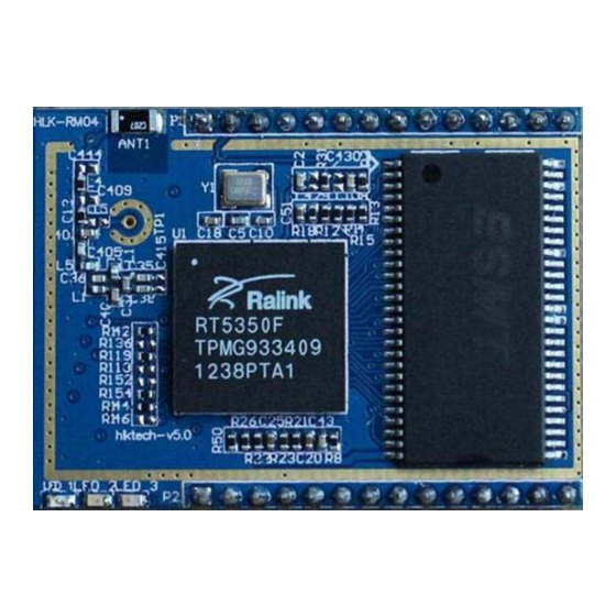
Page 4: Hardware Explanation
Serial baud rate 50~230400bps Other Parameters Status indicator Status indicator Operating temperature:-20-70℃ Operating humidity:10%-90%RH(不凝结) Environmental standard Storage temperature:-40-80℃ Storage humidity:5%-90%RH(不凝结) Additional properties Frequency bandwidth optional:20MHz、40MHz,自动 2.2 Hardware Explanation 2.2.1 Mechanical Dimensions HLK-RM04 Mechanical Dimensions is shown in the following picture:... - Page 5 Picture2.Dimensions Unit:mm 2.2.1.1 Contact Pin Interface The Pin of this product as shown above is defined as follows: Table2-2 module pin interface Function Direction Explanation Supply Voltage, 5V+/-10% VCC5V Analogue Ground WLAN Activity LED WIFILED 3.3V Output (Suuport Atmost 300mA) VO3.3 10/100 PHY Port #1 activity LED LINK1...
-
Page 6: Quick Start
value 10/100 PHY Port #1 TXP TXOP1 10/100 PHY Port #1 TXN TXON1 10/100 PHY Port #2 TXP RXIP2 10/100 PHY Port #2 TXN RXIN2 10/100 PHY Port #1 RXN RXIN1 10/100 PHY Port #1 RXP RXIP1 10/100 PHY Port #2 OXN TXON2 10/100 PHY Port #2 OXP TXOP2... -
Page 7: Configurate Serial Network Parameter
AT command mode first. WEB configuration Through the correct module address,you can access to the WEB configuration page. WEB network configuration Detailed information can refer to<<HI-LINK Router User manual>> WEB serial configuration Serial Web configuration page:192.168.16.245/ser2net.asp is as follows:... - Page 8 Current shows the current configuration , Updated shows the current revision rameters。Submit submit the revision. Serial Configure:Serial configuration.fomat:Baud rate, data bits, parity bit, stop bit. r example: “115200,8,n,1”. rial Framing Lenth:The Lenth of Serial Framing rial Framing Timeout:The time of Serial Framing twork Mode:choose Client、Server or none。...
-
Page 9: Serial At Command Configuration
Network Protocol:Use tcp or udp Protocol Network Timeout:Under the server network mode, no data transmis sion within the timeout period, e connection will be disconnected. 0 specifies never disconnected. Serial AT command configuratio Access to AT command mode Module in network fault, such as fault allocation situation will automatically exit the transparent transmission mode, enter AT instruction mode. -
Page 10: Restore Factory Settings
remotepro Network Protocol type timeout Network timeou mode Network mode uart Serial port configuration uartpacklen Serial group frame length uartpacktimeout Serial framing time save Save the configuration and start service reconn Restart services Parameter definition is consistent with the web configuration parameter. Restore factory Settings Support the following way s to restore the factory settings... -
Page 11: Firmware Upgrade
100ms Trst Firmware upgrade 1. Restore the factory value. 2. Pc can connect with module through Ethernet, ip: 192.168.16.123/255.255.255.0. Browser visits 192.168.16.254. Username / password: admin / admin. 3. Open the following page. Select the appropriate firmware, click apply upgrades. Wait a bout 3 minutes. -
Page 12: Serial To Wifi(Ap
4. Open the following page. This page allows you to modify the the LAN port parameters. Set Ethernet ip address, gateway, dns server information, click apply to take effect. 5. At this moment, you must use new ip address to access the web page. Serial to wifi(ap)... - Page 13 2. Pc can connect with module through Ethernet, ip: 192.168.16.123/255.255.255.0. Browser visits 192.168.16.254. Username / password: admin / admin. 3. Open the following page, dhcp type opens the server function. Click APPLY enable. This page allows you to modify the the LAN port parameters. 4.
-
Page 14: Serial To Wifi(Client
5. Open the following page. This page can modify the wifi security related function. You can modify the wifi key. Clicks APPLY to take effect. 6. At this point, connected to the module by other wifi devices. Module IP: 192.168.16.254. Serial to wifi(client)... - Page 15 2. Pc can connect with module through Ethernet, ip: 192.168.16.123/255.255.255.0. Using Browser to access to 192.168.16.254. Username / password: admin / admin. 3. Open the following page, set to Ethernet Converter mode.Click on the APPLY to take effect. 4. Open the following page.Click APPLY to increase AP information. 5.
- Page 16 6. Open the following page.This page can modify the WiFi security related function.You can modify the WiFi key.Click on the APPLY effect.
- Page 17 7. Open the following page, view IP information of the module.Wan IP address is the ip.If no IP address appears, it means disconnected to AP.
-
Page 18: Appendix A Document Revision Record
Appendix A document revision record Version Revision range Date number 1.00 Draft version 2012-9-10...
Need help?
Do you have a question about the HLK-RM04 and is the answer not in the manual?
Questions and answers