
Related Manuals for Hi-Link HLK-RM60


Summary of Contents for Hi-Link HLK-RM60
- Page 1 Shenzhen Hi-Link Electronic CO.,Ltd HLK-RM60 User Manual Version:V1.0 Revised Date:20210508 Copyright © Shenzhen Hi-Link Electronics Co., Ltd. ...
-
Page 2: Table Of Contents
Contents 1. PRODUCT INTRODUCTION..........................- 1 - 1.1. OVERVIEW................................ - 1 - 1.2. PRODUCT FEATURES............................. - 1 - 2. DIAGRAM..................................- 2 - 2.1. SPECIFICATION............................... - 3 - 2.2. NUMBER OF INTERFACES..........................- 3 - 2.3. TECHNICAL SPECIFICATIONS........................- 4 - 2.4. -
Page 3: Product Introduction
User Manual 1. Product Introduction Overview HLK-RM60 is a high-performance embedded WIFI6 module launched by Hilink Electronics. The module complies with IEEE standard 802.11a/b/g/n/ac/ax. The module integrates a 2.4G/5.8G radio frequency transceiver with a transmission rate. High characteristics. Product Features ... -
Page 4: Specification
User Manual Specification Items Parameter Notes Model Number HLK-RM60 Main Chipset MT7621 Kernel MIPS1004Kc Main frequency 880MHz DDR2 128MB Flash 16MB Ambient temperature: -20℃~+60℃ Temperature Using:10~95%(Non-condensing) Humidity Stock:5~95%(Non-condensing) Size 90mm×60mm Number of interfaces Interface Quantity Default firmware Support WiFi Standard IEEE 802.11b/g/n/a/ac/ax... -
Page 5: Technical Specifications
User Manual Technical specifications Model Number HLK-RM60 Module Package In-line IEEE 802.11 a/b/g/n/ac/ax Wireless standard 2.4G Wi-Fi: 2412-2462MHz ; Frequency Range 5G Wi-Fi: 5150-5250MHz, 5725-5850MHz 802.11b: +18.99dBm 802.11g: +18.65dBm, 802.11a: +16.80dBm Transmit power 802.11n20: +23.69dBm, 802.11ac20: +19.64dBm 802.11n40: +21.48dBm, 802.11ac40:+20.00dBm Wireless 802.11ax20: +19.56dBm , 802.11ax40: +20.29dBm... -
Page 6: Application Field
User Manual Application field Smart home; Instrumentation; Wi-Fi Remote monitoring/control ; Toy field; Color LED control; Intelligent integrated management of fire protection and security; Smart card terminals, wireless POS machines, handheld devices, etc. 2. -
Page 7: Pin Introduction
User Manual 3. Pin introduction Figure 2. Module pin sorting - 5 -... - Page 8 User Manual Table 3. Module pin sorting 1:3.3VD 2:GND 39:ND_D2 40:ESW_TXVN_D_P1 77:I2C_SDA 78:GND 3:3.3VD 4:GND 41:ND_D1 42:GND 79:NC 80:ESW_TXVP_A_P4 5:3.3VD 6:GND 43:ND_D0 44:ESW_TXVP_A_P2 81:WDT_RST_N 82:ESW_TXVN_A_P4 8:ESW_TXVP_A_P0 7:3.3VD 45:ND_RB_N 46:ESW_TXVN_A_P2 83:ESW_P4_LED 84:ESW_TXVP_B_P4 9:3.3VD 10:ESW_TXVN_A_P0 47:ND_RE_N 48:ESW_TXVP_B_P2 85:ESW_P3_LED 86:ESW_TXVN_B_P4 11:NC 12:ESW_TXVP_B_P0 49:ND_CS_N 50:ESW_TXVN_B_P2 87:ESW_P2_LED 88:ESW_TXVP_C_P4...
- Page 9 User Manual Power pin description: Name Type Function description Default function 3.3VD 3.3V Input,Current≥1500mA Power Supply Ground Power Supply USB3.0 Interface Description: SSUSB_TX_P SSUSB_TX_N USB3.0 SSUSB_RX_P USB3.0 SSUSB_RX_N USB_D_N USB 3.0 Interface HS/FS/LS Pin USB_D_P - 7 -...
- Page 10 User Manual SPI Interface Description: ND_D7 SPI_HOLD GPIO#40 ND_D6 SPI_WP GPIO#39 ND_D5 SPI_MOSI GPIO#38 ND_D4 SPI_MISO GPIO#37 ND_RE_N SPI_CLK GPIO#36 ND_WE_N SPI_CS1 GPIO#35 ND_CS_N SPI_CS0 GPIO#34 SDIO Interface Description: ND_WP SD_WP GPIO#41 ND_RB_N SD_CLK GPIO#42 ND_ALE SD_CMD GPIO#44 ND_CLE SD_CD GPIO#43 ND_D0 SD_DATA0...
- Page 11 User Manual I2C Interface: 75:I2C_SCLK I2C_SCLK/GPIO#3 GPIO#3 77:I2C_SDA I2C_SDA/GPIO#4 GPIO#4 Network port P0 System reset: ESW_TXVP_A_P0 ESW_TXVN_A_P0 ESW_TXVP_B_P0 Network port 0 , Please leave it in the air if you don;t ESW_TXVN_B_P0 PORT0 Interface need it ESW_TXVP_C_P0 ESW_TXVN_C_P0 ESW_TXVP_D_P0 ESW_TXVN_D_P0 Network port P1 Interface:...
- Page 12 User Manual Network port P3 Interface: ESW_TXVP_A_P3 ESW_TXVN_A_P3 ESW_TXVP_B_P3 Network port 3,Please leave it in the air if you don;t ESW_TXVN_B_P3 PORT3 Interface need it ESW_TXVP_C_P3 ESW_TXVN_C_P3 ESW_TXVP_D_P3 ESW_TXVN_D_P3 Network port P4 Interface: ESW_TXVP_A_P4 ESW_TXVN_A_P4 ESW_TXVP_B_P4 Network port 4 , Please leave it in the air if you don;t ESW_TXVN_B_P4 PORT4 Interface need it...
-
Page 13: Size
User Manual Other Pins : Hang in the air Hang in the air Hang in the air Hang in the air Hang in the air Hang in the air : Remark , ; ; ; 。 。 I-Input O-Output I/O-Number I/O P-Power NC Hang in the air 4. -
Page 14: Indicator Light Description
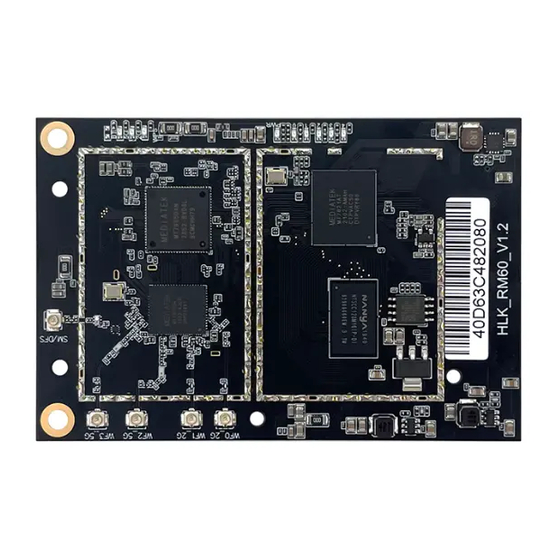
User Manual Wifi Light Fixing hole 5.8G wifi Ant 2.4G wifi Ant Connect port Network&Power light Figure 4 Module interface description 5. Indicator light description 2G/5G wifi indicator light: After turning on the wifi function, the module wifi indicator will flash, after turning off the wifi indicator, the module’s wifi indicator will go out. - Page 15 User Manual 7. Enter the configuration web interface Connect the computer's network port and the module's LAN port, open the computer browser, enter 192.168.16.254, and you will enter the web login interface, enter the user name: root, password: admin, and then click the Login button to enter the configuration interface.
- Page 16 User Manual 8. Set the wifi name After entering the web configuration interface, click WIFI, select WIFI configuration, enter the wifi configuration interface Figure 7 Enter the wifi setting interface - 14 -...
- Page 17 User Manual In this interface, you can see the WiFi name and mac address of 2.4g and 5.8g, click the config button to enter the corresponding configuration interface Figure 8 Wifi Status page After clicking the config button, you will enter the configuration interface of the corresponding ssid and password Figure 9 Wifi Setting Page - 15 -...
- Page 18 User Manual After the configuration is completed, click the following button to make the configured information take effect. Figure 10 Save Button Appendix A Document revision history Version Revision scope Date V1.0 Original Version 20210508 - 16 -...
- Page 19 User Manual FCC Caution: Any Changes or modifications not expressly approved by the party responsible for compliance could void the user's authority to operate the equipment. This device complies with part 15 of the FCC Rules. Operation is subject to the following two conditions: (1) This device may not cause harmful interference, and (2) this device must accept any interference received, including interference that may cause undesired operation.
- Page 20 User Manual other transmitters, digital circuitry, or due to physical properties of the host product (enclosure). This investigation is especially important when integrating multiple modular transmitters where the certification is based on testing each of them in a stand‐alone configuration. It is important to note that host product manufacturers should not assume that because the modular transmitter is certified that they do not have any responsibility for final product compliance.
Need help?
Do you have a question about the HLK-RM60 and is the answer not in the manual?
Questions and answers