Table of Contents
Advertisement
Advertisement
Table of Contents

Related Manuals for Dynamic Shark


Summary of Contents for Dynamic Shark
- Page 1 SHARK Quick Start Guide Issue 1, December 2011...
-
Page 2: About This Manual
About this manual This manual must be read together with all other relevant SHARK Module manuals, as well as all applicable Dynamic Controls Technical Service Bulletins (TSBs), application notes and service instructions. In this manual, a few symbols will help you identify the purpose of the paragraph that follows: Notes &... -
Page 3: Table Of Contents
About this manual ............................. 2 Contents ................................3 Introduction ................................ 4 The SHARK system .............................. 4 Turning the SHARK on and off ........................5 Using the SHARK Lock ........................... 6 Waking up from Sleep Mode ........................6 Driving ................................7 Using the Speedometer .......................... -
Page 4: Introduction
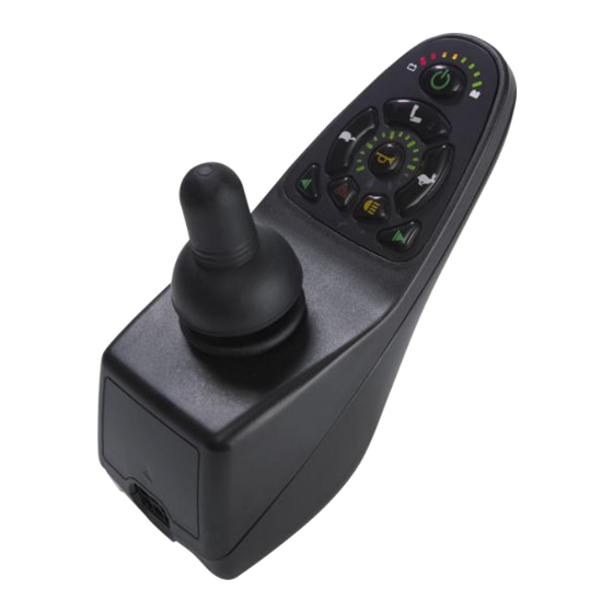
Introduction This is a quick start guide for the SHARK powerchair controller system. It provides an overview of the SHARK system, a “How to….” section, and a troubleshooting section. For details concerning installation and programming and more detailed diagnostics, please consult the relevant installation manuals (see the Further reading section for more details). -
Page 5: Turning The Shark On And Off
Out Of Neutral At Power Up (OONAPU) If the SHARK is turned on while the joystick is not in the centre position, an “Out Of Neutral At Power Up” fault occurs. -
Page 6: Using The Shark Lock
Using the SHARK Lock If the Lock Enable parameter is set to 'Yes', the SHARK can be locked by pressing the on/off button for more than 4 seconds. Lock the SHARK to prevent unauthorized persons from operating the chair. To lock the SHARK Press the on/off button for 4 seconds when the SHARK is turned on. -
Page 7: Driving
Speed speed (that has been set with the speed buttons) is reached. If the bottom-left GREEN LED is flashing, SHARK is in speed limit mode. This happens when the chair is in an unstable position and driving too fast may be dangerous, for example when the seat is raised or tilted. -
Page 8: Using The Horn
Battery Gauge Meaning Drive Inhibit, the chair will not drive. For example, when a charger is connected to the SHARK. The LEDs turn on one by one from left to right. A fault has occurred. All LEDs turn on one by one from left to right to indicate that the chair will not drive. -
Page 9: Battery Charging
When the Battery Charger shows a „full‟ battery charge, you can remove the charger from the SHARK. Do not use the indication on the battery gauge. Only use the indication on the battery charger itself to see when charging is complete. -
Page 10: Using The Lights
Joystick Switch Threshold parameter, except in proportional mode. Using the Lights To operate the lights Press the side light button to switch the side/positioning lights on or off. REMD21 The side light LED is on when the sidelights are switched on. REMD31 The SHARK system... -
Page 11: Operating Attendant Mode
Control LED is on. In Attendant Mode, the joystick of the REMD will not operate. Only the joystick on the DK-ACU is operational. See the DK-ACU Installation Manual for further details. DK-ACU in Attendant Mode Attendant Control LED is on The SHARK system... -
Page 12: How To
How to… How to set the speedometer If your SHARK remote has a speedometer display, it can be used in two different display modes: Max Speed Only, or Speedo Plus Max Speed. Max Speed Only Display If the speedometer is set to display Max Speed Only, the... -
Page 13: How To Use The Virtual Speed Pot
If adjusting the speed in fine steps does not work, simultaneously hold down the „slower‟ and „faster‟ buttons for 2 seconds to activate fine speed control. The SHARK will beep when the mode has been changed. -
Page 14: How To Improve Load Compensation For Low Speeds
To improve load compensation for low speeds, set the value of the Load Compensation parameter to the correct motor resistance value of the used motor. The Load Compensation parameter can be found by connecting the SHARK system to a PC or laptop, and running the Wizard application. Read the program from the connected controller by pressing the Wizard button shown to the left. - Page 15 The Load Compensation parameter is located in the Drive Programs section (see figure below). How to change Load Compensation To change the Load Compensation value, click on one of the Program columns for Load Compensation as outlined in red in the figure above.
-
Page 16: How To Configure A Short-Throw Joystick
If the powerchair user has difficulty moving the joystick to full deflection, then the joystick can be re-configured for short-throw operation. Normally the SHARK controller will drive at full speed only when the joystick is pushed as far as it can mechanically go, that is, when it hits the restrictor plate. -
Page 17: How To Read Powerchair-Specific Information
How to read powerchair-specific information It is often useful to know the details and history of a powerchair system, especially for maintenance or fault finding purposes. In this section of the „How to…‟ we will show you how to obtain information for both the Remote and Power Module, such as: Serial numbers Time powered up Number of times driven... -
Page 18: How To Swap An Active Program In The Field
How to swap an active program in the field The active Drive Program defines the driving performance of the powerchair; in the SHARK power module, three default programs have already been defined for you. If the active program does not suit your user, then you can quickly change the active Drive Program using the HHP (see steps 1 &... - Page 19 Current active program Step 5 – customise Drive Program (optional) Each Drive Program can be customised further using the HHP, to suit your user‟s needs. After you have selected the appropriate Drive Program (steps 1 - 4, above), cycle the power on the controller to exit the Technician mode.
-
Page 20: Troubleshooting Guide
Troubleshooting Guide When troubleshooting a powerchair system, follow the three-part steps outlined below. Part 1: Check the battery voltage. Part 2: Check for possible “Flash Code” on remote. Part 3: Check for other conditions displayed by the controller. These steps are detailed more fully in the following pages. Troubleshooting Guide... -
Page 21: Part 1 Check The Battery Voltage
Part 1 Check the battery voltage. When troubleshooting a powerchair, battery voltage is always the first thing to check. Check the battery voltage through the 3-pin battery charger port located on the front of the controller. Set voltmeter to the 50 volt dc (V dc) scale. Place the leads into the two outside pins of the battery charger port as shown in the image to the right. -
Page 22: Part 2 Check "Flash Code" On Remote
Part 2 Check “Flash Code” on remote. If a fault condition exists, the Fault Indicator LED shows a Flash Code. A flash code is a specific number of short flashes, followed by a pause. Flash Code If the fault is a serious fault that prevents the chair from driving, the Battery Gauge shows a 'Drive Inhibit' indication. - Page 23 Possible motor short circuit check the motor cables for damage Motor brushes may be too stiff and bouncing Otherwise internal controller fault, contact Dynamic Controls Intermittent short circuit Check for damaged cables Motor brushes may be too stiff, bouncing against the case...
- Page 24 Fault finding motor problems: 1 Swap the M1 and M2 motor connectors (if motor connectors are un-keyed): Plug the M1 motor into the M2 motor connector and M2 motor into the M1 motor connector. If the flash code stays the same, then the fault is in the controller. If the flash code changes to the opposite motor then the fault lies in the motor.
- Page 25 Fault during power-up testing Check if the cables of the park brake are loose or damaged Park brake short circuit or broken Check the park brake cables for damage Notes for Flash Codes 5 & 6: 1 Check to see if the park brake lever is disengaged: If disengaged, re-engage park brake lever and turn power off and back on to reset flash code.
- Page 26 Attendant remote fault Check attendant remote cables for damage Disconnect and reconnect attendant remote If the fault doesn‟t go away, disconnect the attendant remote as a temporary solution and contact Dynamic Controls Internal fault other Contact Dynamic Controls Notes for Flash Code 7: 1 Holding down the power for a time greater than 4 seconds while powering up will cause the remote to display this flash code.
- Page 27 Loss of communication with attendant remote Disconnect and reconnect attendant remote and try again Check the attendant remote cables If the fault doesn‟t go away, disconnect the attendant remote as a temporary solution and contact Dynamic Controls Flash Fault source Meaning &...
-
Page 28: Part 3 Check For Other Conditions Displayed By The Controller
If after performing the previous tests and the flashing still persists, the controller will need to be returned. 2 A right-to-left LED chase on the battery gauge signifies that the Shark is in a locked state: To un-lock the Shark, turn the controller on and press the horn button twice within ten seconds. -
Page 29: Using Hhp Diagnostics
Using HHP diagnostics The HHP (Hand-held Programmer) can provide a quick and easy way to view the SHARK system‟s faults and usage statistics. Simply plug in the HHP (using a DK-ADAPT adapter) and power-up the SHARK system. - Page 30 Step 3 – View Time On Usage Statistics The Fault log is displayed a page at a time. To view older faults, press the MORE soft key. To view Usage Statistics, press the NEXT soft key. Step 4 – View Powered Usage Statistics The first usage statistic is Time on which displays the number of hours the system has been run.
-
Page 31: Further Reading
Dynamic Controls SHARK DK-REMB Installation Manual (GBK80261) Dynamic Controls SHARK DK-REMD/REMDB Installation Manual (GBK80258) Dynamic Controls SHARK DK-ACU Installation Manual (GBK80257) For a complete list of programming and wiring information for the SHARK system, see the Power Module Installation Manual (GSM80262). Glossary Attendant Control Unit –... -
Page 32: Index
Seat Control Type ............ 10 Seating Functions............9 Seating Mode ............. 9 General Settings ............12 Serial numbers ............17 SHARK system ............31 Short-throw joystick ..........16 Hand-held Programmer ........... 29 Sleep Mode ..............6 Hazard Lights ............11 Sleep Timer .............. - Page 33 Speedo Plus Max Speed ........... 12 System Information ..........17 Usage statistics ..........29, 30 Time on ..............29 Wakeup Style ............. 6 Time powered up ............. 17 Wizard ..............31 Troubleshooting ............20 XLR socket ..............9 Index...
- Page 34 Dynamic Controls was established in 1972 and is headquartered in New Zealand. Regional centres are located in Europe, United States, Asia, and Australasia. ISO 13485 certified – Dynamic Controls goes above and beyond industry standard expectations to ensure customers receive the best products possible.
Need help?
Do you have a question about the Shark and is the answer not in the manual?
Questions and answers