
Subscribe to Our Youtube Channel
Related Manuals for Dynamic RHINO2 DS90


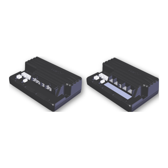
Summary of Contents for Dynamic RHINO2 DS90
- Page 1 Scooter Controllers NSTALLATION ANUAL RHINO2 DS90, DS120, DS160 and DS180 RHINO2 GBK51948 Issue 5 Jul 2023...
- Page 2 Page left blank intentionally...
- Page 3 If there is a specific requirement for your application, please contact Dynamic Controls or one of the sales and service agents to assist you. This manual must be read together with all other relevant scooter component manuals.
-
Page 4: Variations By Profile
Installation Manual Issue 5 This manual supersedes all previous issues, which must no longer be used. Note Get the latest version of this manual from Dynamic Controls' website: www.dynamiccontrols.com reserves the right to change the product without notification. YNAMIC Any attempt to gain access to or in any way abuse the electronic components and associated assemblies that make up the scooter system renders the manufacturer’s... -
Page 5: Table Of Contents
GBK51948 RHINO2 Installation Manual Issue 5 2 Contents 1 About this manual 2 Contents 3 Introduction 3.1 Rhino2 overview 3.2 Rhino2 features 4 Specifications 4.1 Electrical Specifications 4.2 Physical Specifications 5 Installation and testing 5.1 Mounting 5.1.1 General Mounting Conditions 5.1.2 Mounting Orientation 5.2 Attaching the terminal cover 5.3 Connections and Wiring... - Page 6 6 Programming 6.1 The Hand Held Programmer (HHP) 6.1.1 Programming menu 6.1.2 Diagnostics menu 6.1.3 Technician menu 6.2 Dynamic Wizard 6.2.1 Software version and module version 6.3 Parameter List 6.4 Parameter Variations 6.4.1 Variations by module 6.4.2 Variations by Profile 1 6.4.3 Variations by Profile 2...
-
Page 7: Installation Manual Issue
GBK51948 RHINO2 Installation Manual Issue 5 7.6 Service Scheduler 7.7 Status Information — Single Wire Communications 7.7.1 Status information overview 7.7.2 Physical interface 7.7.3 Protocol 8 Appendices 8.1 Neutral Detect Active States 8.2 Parts List 8.3 Intended Use and Regulatory Statement 8.3.1 Intended Use 8.3.2 Device Classification 8.3.3 Compliance and Conformance with Standards... - Page 8 GBK51948 RHINO2 Installation Manual Issue 5 Page left blank intentionally Page 6...
-
Page 9: Introduction
GBK51948 RHINO2 Installation Manual Issue 5 3 Introduction 3.1 Rhino2 overview 3.2 Rhino2 features Introduction - Page 7... - Page 10 GBK51948 RHINO2 Installation Manual Issue 5 3.1 R 2 overview HINO The R 2 scooter controllers provide a reliable, refined, cost-effective control solution for HINO most mobility scooters, and includes: HINO Model Description DS90 90A Controller DS120 120A Controller DS160 160A Controller DS180 180A Controller...
- Page 11 GBK51948 RHINO2 Installation Manual Issue 5 Compliant with EU Directive 2011/65/EU of 8 June 2011 – Restrictions on use of Hazardous Substances (RoHS) Note Unless otherwise specified, all references in this manual apply to all variants of the R 2 controller. HINO Note The R...
- Page 12 GBK51948 RHINO2 Installation Manual Issue 5 Page left blank intentionally Page 10...
-
Page 13: Specifications
GBK51948 RHINO2 Installation Manual Issue 5 4 Specifications 4.1 Electrical Specifications 4.2 Physical Specifications Specifications - Page 11... -
Page 14: Electrical Specifications
GBK51948 RHINO2 Installation Manual Issue 5 4.1 Electrical Specifications Parameter Description Compatible Battery 24 V supply, 2 x 12 V in series, circuit breaker protected Supply Compatible Motor 24 V DC permanent magnet type, typically rated 200-1000 watts. Nominal Units Note 1 Operating Voltage ( V batt... - Page 15 GBK51948 RHINO2 Installation Manual Issue 5 Parameter Description Nominal Units Boost Current Boosted Current Boost Time Park Brake Output Voltage Current 1.25 Note 1: The RHINO2 transitions to Limp Mode when the battery voltage falls below its cut-off voltage or exceeds 30 V. During Limp Mode, the scooter can continue to be driven, albeit at a reduced speed.
-
Page 16: Physical Specifications
GBK51948 RHINO2 Installation Manual Issue 5 4.2 Physical Specifications Parameter Description Aluminium Top, Base and Terminal cover Aluminium alloy ADC12 Protection Rating (with cover) Electronics rated to IP55 Protection Rating (without cover) Electronics rated to IP54 Shipping Weight: DS90, 120, 160, 180 Controller Unit 952 grams Terminal cover... -
Page 17: Installation And Testing
GBK51948 RHINO2 Installation Manual Issue 5 5 Installation and testing 5.1 Mounting 5.1.1 General Mounting Conditions 5.1.2 Mounting Orientation 5.2 Attaching the terminal cover 5.3 Connections and Wiring 5.3.1 General Wiring Recommendations 5.3.2 Wiring Diagram for DS90 and DS120 5.3.3 Wiring Diagram for DS160 and DS180 5.4 Battery Connections 5.5 Motor Connections 5.5.1 Motor Protection... -
Page 18: Mounting
GBK51948 RHINO2 Installation Manual Issue 5 5.1 Mounting 5.1.1 General Mounting Conditions Figure 5: R 2 Mounting Configuration HINO The position and orientation should give maximum mechanical protection to the controller. Mount out of the path of water splashes from wheels or cowling and protect the connector panel from direct splashing. -
Page 19: Mounting Orientation
GBK51948 RHINO2 Installation Manual Issue 5 5.1.2 Mounting Orientation Recommended mounting orientation The recommended mounting orientations for R 2 units are vertical (with connector side HINO on the bottom) and horizontal (with connector facing upwards or downwards). The horizontal (with connector facing downwards) mounting orientation is permitted to be tilted a further 30°... - Page 20 GBK51948 RHINO2 Installation Manual Issue 5 Mounting orientation to be avoided The horizontally tilted mounting orientations and vertical (with connector side on the top) orientation, which have chances of water and dirt accumulation, are not recommended. Figure 9: Horizontally Tilted Mounting Orientations Figure 10: Vertical (Connector side on the top) Mounting Orientation Page 18 - Installation and testing...
-
Page 21: Attaching The Terminal Cover
GBK51948 RHINO2 Installation Manual Issue 5 5.2 Attaching the terminal cover An optional terminal cover is available for the R 2 controller. This can be ordered HINO separately – see 8.2 Parts List for more details. The terminal cover kit comprises a terminal cover and three M3x8mm screws. To attach the terminal cover, offer it towards the top case ensuring that the locating-lugs (see image below) are positioned in the recesses in the top case, and then screw the terminal cover to the top case with the M3 screws provided. -
Page 22: Connections And Wiring
GBK51948 RHINO2 Installation Manual Issue 5 5.3 Connections and Wiring 5.3.1 General Wiring Recommendations To maximise performance, minimise EMC emissions, maximise EMC and ESD immunity, and to keep the cabling of the scooter safe and tidy, please observe the following guidelines. Keep all cables as short as possible. - Page 23 GBK51948 RHINO2 Installation Manual Issue 5 Warning 1. Route the cables and fasten all scooter components in a position so that the cables, the connectors and the connector sockets of the R 2 do not allow water entry or suffer from physical strain, abuse or HINO damage, such as cutting or crushing.
-
Page 24: Wiring Diagram For Ds160 And Ds180
GBK51948 RHINO2 Installation Manual Issue 5 5.3.2 Wiring Diagram for DS90 and DS120 Figure 12: Wiring Diagram for DS90 and DS120 5.3.3 Wiring Diagram for DS160 and DS180 Figure 13: Wiring Diagram for DS160 and DS180 Warning The fuses shown in these diagrams should be located as close to the controller as is practical to minimise the length of unprotected cables. -
Page 25: Battery Connections
DS160: 2 x 5mm (2 x 10AWG) negative DS180: 2 x 5mm (2 x 10AWG) Mating Connector Part Numbers DS90, DS120 Dynamic Part # Part Description Supplier Part # GCN51971 6W Housing 250 Series Plug V0 GCN0690 Terminal Female 12-14AWG... - Page 26 GBK51948 RHINO2 Installation Manual Issue 5 The torque settings for the DS160 and DS180 battery terminal’s screws should be between 4.5Nm and 5.5Nm. For DS90 and DS120 units, it is essential that at least four (2 pairs) battery terminals are used. Note A thermal circuit breaker or fuse must be installed between the battery supply and the controller, to protect both the batteries and the system wiring.
-
Page 27: Motor Connections
DS160: 2 x 5mm (2 x 10AWG) negative DS180: 2 x 5mm (2 x 10AWG) Mating Connector Part Numbers DS90, DS120 Dynamic Part # Part Description Supplier Part # GCN51970 4W Housing 250 Series Plug V0 GCN0690 Terminal Female 12-14AWG... -
Page 28: Motor Protection
GBK51948 RHINO2 Installation Manual Issue 5 5.5.1 Motor Protection To prevent the motor from overheating, the motor protection function can reduce the performance of the scooter when the motor consumes too much power for a prolonged period. Enable motor protection with the Motor Protection parameter. -
Page 29: Park Brake Connections
Park Brake Connections Function Wire Gauge Park Brake Negative 0.5mm / 20AWG Park Brake Positive Mating Connector Part Numbers Dynamic Part # Part Description Supplier Part # GCN0884 Molex ‘Mini-Fit Jr’ 2-socket housing 39-01-3028 GCN0771 Molex ‘Mini-Fit Jr’ Receptacles 18-24AWG... - Page 30 GBK51948 RHINO2 Installation Manual Issue 5 Figure 15: Alternative Park Brake Wiring using a mechanical release lever Alternatively, a normally closed micro-switch can be placed in series with the park brake. This will cause a Flash Code 5 to be displayed and the scooter will be unable to drive. To clear the fault, engage the park brake and turn the power off and then on again.
-
Page 31: Park Brake Testing
(16-18AWG) 0.5mm² External Ambient Temperature Sensor Input (18-20AWG) 0.5mm² Multifunction Input/Program (P/I) (18-20AWG) Mating Connector Part Numbers Dynamic Part # Part Description Supplier Part # GCN0886 Molex ‘Mini-Fit Jr’ 4-socket housing 39-01-3048 Molex ‘Mini-Fit Jr’ Receptacles GCN0776 39-00-0212 16AWG (0.8 – 1.3mm² wire) Molex ‘Mini-Fit Jr’... -
Page 32: Battery Charger Connections
GBK51948 RHINO2 Installation Manual Issue 5 5.7.1 Battery charger connections Warning The scooter manufacturer should comply with the requirements of ISO7176, Part 25 regarding batteries and chargers. The maximum charging current for the RHINO2 scooter control system is 8A RMS. The scooter manufacturer must specify an appropriate battery charger for the batteries used in the scooter. - Page 33 GBK51948 RHINO2 Installation Manual Issue 5 Alternatively, any of the Multifunction Input pins that support the Slow function may be used. In this case, set Slows to to 0 and set Latches to 'Yes'. If Latches is set to 'Yes', a power cycle is required to be able to drive again.
-
Page 34: Programmer Connections
The R 2 can be programmed with two different programming tools: HINO The DX-HHP hand-held programmer (6.1 The Hand Held Programmer (HHP) The PC-based Wizard programmer (6.2 Dynamic Wizard) Figure 20: Programming adaptors Programming socket Adaptors needed XLR Charger socket... -
Page 35: External Ambient Temperature Sensor Connection
GBK51948 RHINO2 Installation Manual Issue 5 5.7.3 External Ambient Temperature Sensor Connection RHINO2 provides support for an external temperature sensor that can be connected to the charging/programming connector between pin 3 (External Ambient Temperature Sensor Input) and pin 1 (Battery Negative) — see Figure Figure 21: Connecting an NTC thermistor ambient temperature sensor ‡1... -
Page 36: Tiller Connector
1.0mm² Battery Negative (B-) (18AWG) Multifunction Input (Charger Inhibit) 0.5mm² (20AWG) Mating Connector Part Numbers Supplier Part Dynamic Part # Part Description GCN0887 Molex ‘Mini-Fit Jr’ 14-socket housing 39-01-2145 Molex ‘Mini-Fit Jr’ Receptacles GCN0776 39-00-0212 16AWG (0.8 – 1.3mm² wire) Molex ‘Mini-Fit Jr’... -
Page 37: Throttle Configuration
GBK51948 RHINO2 Installation Manual Issue 5 5.9 Throttle Configuration Select the correct throttle type with the Throttle Type parameter: Throttle Type Description Wig-wag To swap the forward and reverse directions (for left-handed use), set the Swap Throttle Direction parameter to 'Yes'. Uni-polar The scooter moves in the same direction for both sides of the throttle. -
Page 38: Single Throttle Wiper
GBK51948 RHINO2 Installation Manual Issue 5 The R 2 supports three throttle configurations: HINO Single throttle wiper ( see 5.9.2 Single throttle wiper) This option is compatible with previous Rhino products. However, if the installation foreseeably allows a leakage current between either a 24 V supply or reference line and the speed potentiometer wiper line, the system will fail the ISO7176 leakage current requirement. -
Page 39: Neutral Detect
GBK51948 RHINO2 Installation Manual Issue 5 Warning If the throttle potentiometer is powered externally (not by T+ and T-), take extreme care to avoid ground shift. The R 2 can interpret a ground shift voltage as a drive signal and the scooter might start driving. If the HINO throttle must be powered externally, either use additional hardware as described below or use the Neutral Detect feature (see... - Page 40 GBK51948 RHINO2 Installation Manual Issue 5 Figure 24: Neutral detect function * The Neutral Detect switch can be connected to B+ or B-, dependent on which option is selected in the Active field of the Pin [x] Function parameter. For more information, see 6.5.9.2 Active States 8.1 Neutral Detect Active States...
- Page 41 GBK51948 RHINO2 Installation Manual Issue 5 Figure 25: Disk with micro-switch Make sure that the notch is not too deep and that is does not have sharp edges, otherwise the user may have difficulty to move the throttle out of the neutral position and the disk may slide out of position during use.
-
Page 42: Two Throttle Wipers - Mirrored
GBK51948 RHINO2 Installation Manual Issue 5 5.9.4 Two throttle wipers - mirrored The R 2 supports the use of a 2 x 10 kΩ dual-gang throttle with two linear wiper signals HINO that are each other's opposite. The throttle can either be a short travel or long travel variant. -
Page 43: Speed Limit Pot Connections
GBK51948 RHINO2 Installation Manual Issue 5 6.1.1.3 Throttle calibration in the programming section for details. Note To calibrate the throttle with the Wizard PC-based programmer, use the HHP emulator mode: Tools -> Plug-ins -> HHP Emulation 5.9.6 Speed Limit Pot Connections A speed limit pot may be connected either in series with the throttle wiper, or in parallel by using the dedicated input Pin 9 (Speed Limit Pot wiper), Pin 2 (Throttle Positive) and Pin 8 (Throttle Negative). -
Page 44: Alternative Speed Reduction Options
GBK51948 RHINO2 Installation Manual Issue 5 5.9.6.2 In parallel with the throttle For a speed pot in parallel, use a 100kΩ Speed Pot in Parallel (Pin 9) potentiometer and set Speed Limit Pot to 'Yes'. If the Speed Limit Pot is at its minimum position, the speed of the scooter at full throttle deflection is set Lowest (Minimum) Forward Speed Lowest... - Page 45 GBK51948 RHINO2 Installation Manual Issue 5 Option Description Proportional speed reduction As a conventional User Control potentiometer, the SRW supports the use of a 10k logarithmic pot wired as a variable resistor between Pin x (4, 6 or 12) and B– of the tiller. SRW (variable) supports a user-defined resistance value, between Pin x (4, 6 or 12) and B–...
-
Page 46: Tiller Battery Supply
GBK51948 RHINO2 Installation Manual Issue 5 Option Description Slow/Stop This function has three states: Inactive, Slow and Stop. When Slow is active, the scooter will slow to a programmed speed limit (a percentage of the maximum speed). Has no effect on scooter acceleration or deceleration. -
Page 47: Key Switch Input
GBK51948 RHINO2 Installation Manual Issue 5 5.9.9 Key Switch Input Pin 5 of the tiller connector provides the key switch power circuit. A high-quality key switch (> 50,000 operations) should be used. Up to two status LEDs (up to 10 mA each) may be wired in line with this output as an alternative to using one of the Status output pins. -
Page 48: Beeper Output
“LED Battery Gauge” wiring shown on the right. The algorithm used is the same as the Dynamic Shark power chair controller and has built-in filters to adjust for voltage dips under load and floating voltages after periods of idling. -
Page 49: Brake And Reversing Lights
GBK51948 RHINO2 Installation Manual Issue 5 5.9.13 Brake and Reversing Lights Pin 3 and Pin 11 on the tiller connector can be configured as either a brake light or reversing light. Either light output may be connected to an LED array (500 mA) or relay- driven incandescent or halogen bulb. -
Page 50: Multifunction Pins
GBK51948 RHINO2 Installation Manual Issue 5 5.10 Multifunction Pins The Multifunction Pins maximise flexibility in both scooter design and installation. Scooter variations typically implemented through wiring changes can now be implemented through programming. The R 2 offers both Multifunction Input and Output pins. HINO 5.10.1 Multifunction Inputs The Multifunction Inputs are available on pin 4, 6, 12 and 14 of the Tiller Connector and on... - Page 51 GBK51948 RHINO2 Installation Manual Issue 5 Figure 28: Multifunction Input Pins The configurable options for each input pin are: Active — This defines the circuit state at which the function operates. Slows to — If a Slow function is active, this is the speed the scooter will be limited to.
-
Page 52: Multifunction Outputs
GBK51948 RHINO2 Installation Manual Issue 5 5.10.2 Multifunction Outputs The Multifunction Outputs will output signals dependent on the condition of the controller or batteries. As with the Multifunction Inputs, the Multifunction Output pins have been designed to offer maximum flexibility in the implementation of the scooter feature set and are programmable using the Wizard. -
Page 53: Controller Power Modes
GBK51948 RHINO2 Installation Manual Issue 5 5.11 Controller Power Modes When not powered down, the RHINO2 controller operates within one of three power modes: Normal Mode, Sleep Mode, or Low Power Mode These different modes provide various levels of operation and power usage. Figure 30 shows how the controller transitions from one mode to the next as a consequence of certain events, such as the user turning the key to the ON position (Key... -
Page 54: Sleep Mode
GBK51948 RHINO2 Installation Manual Issue 5 To exit Normal Mode manually, the user must switch the key to its off position (Key OFF), at which point the controller transitions to Low Power Mode (if enabled) or to Powered Down if Low Power Mode is turned off in the programming. If the Sleep Timer has been enabled... - Page 55 GBK51948 RHINO2 Installation Manual Issue 5 Low Power Mode Duration is set to zero, then the controller transitions straight to Powered Down on key off. If the user turns the key to the ON position (Key ON), the controller transitions to Normal Mode.
-
Page 56: Testing
GBK51948 RHINO2 Installation Manual Issue 5 5.12 Testing To ensure that each scooter meets a minimum level of safety, the following procedure should be undertaken. This procedure should be carried out in a spacious environment and with due regard to any possible unexpected scooter movement in the event of faulty installation. -
Page 57: Programming
6 Programming 6.1 The Hand Held Programmer (HHP) 6.1.1 Programming menu 6.1.2 Diagnostics menu 6.1.3 Technician menu 6.2 Dynamic Wizard 6.2.1 Software version and module version 6.3 Parameter List 6.4 Parameter Variations 6.4.1 Variations by module 6.4.2 Variations by Profile 1 6.4.3 Variations by Profile 2... - Page 58 The DX-HHP hand-held programmer (see 6.1 The Hand Held Programmer (HHP) The PC-based Wizard programmer (see 6.2 Dynamic Wizard) Warning No matter which programmer is used, after configuring the system, make sure: the programming has completed correctly and verify that the program has written as requested;...
-
Page 59: The Hand Held Programmer (Hhp)
GBK51948 RHINO2 Installation Manual Issue 5 6.1 The Hand Held Programmer (HHP) The DX-HHP Hand Held Programmer (HHP) is a programming tool that gives access to drive parameters (such as speed and acceleration) and throttle calibration. A technician mode additionally gives access to system settings such as load compensation, and can read extensive system diagnostics such as motor voltage. - Page 60 GBK51948 RHINO2 Installation Manual Issue 5 Figure 33: Programming menu 6.1.1.1 Profile 1/2 The R 2 has two Drive Profiles that are typically used as follows: HINO Drive Profile 1 - Normal Drive Drive Profile 2 - A 'Slow Speed' mode for indoor use, that the user can select with a 'Slow' switch Normally Drive Profile 1 is always selected.
- Page 61 GBK51948 RHINO2 Installation Manual Issue 5 Parameter Lowest (Minimum) Forward Speed Lowest (Minimum) Reverse Speed 6.1.1.2 Non-profiled The parameters that are not in the Drive Profiles can be adjusted in the Non-Profiled menu. Figure 35: Non-profiled menu 1. In the Main Menu screen, press PROG to enter the Programming Menu. 2.
- Page 62 GBK51948 RHINO2 Installation Manual Issue 5 To calibrate a throttle when a throttle fault is active, set Throttle Testing to 'No' with the Wizard, calibrate the unit, and then set Throttle Testing to 'Yes' again. For OONAPU (Out Of Neutral At Power Up) faults, set Throttle OONAPU Testing to 'None' during calibration, and return it to its original setting afterwards.
-
Page 63: Diagnostics Menu
GBK51948 RHINO2 Installation Manual Issue 5 Failed calibration If the controller cannot measure the throttle correctly, or when there is no expected throttle activity for 20 seconds during any of the calibration screens, the HHP will show 'Failed'. Figure 38: Failed calibration If this happens, press RETRY to repeat the calibration from the start, and go back to step 4. -
Page 64: Technician Menu
GBK51948 RHINO2 Installation Manual Issue 5 5. Press NEXT to see the unit identification. Press MORE to see the parameters one by one: Model, ESN and Software version. Identification Description Model The model number of the unit (DS90, DS120 etc.) The serial number of the unit Version The software version number of the unit... - Page 65 GBK51948 RHINO2 Installation Manual Issue 5 In the Technician Menu, the following parameters can be adjusted: Parameter Section Load Compensation 6.5.5.5 Soft Start Period 6.5.3.9 Soft Finish 6.5.3.10 Also, the following parameters can be read in real-time: Parameter Typical Battery Voltage 23 - 28 V Motor Voltage 0 - Battery Voltage...
-
Page 66: Dynamic Wizard
Installation Manual Issue 5 6.2 Dynamic Wizard The PC-based Dynamic Wizard provides access to all the parameters that are allowed to be edited or seen based on the dongle level. In addition, the Wizard can also generate comprehensive diagnostics reports. For more information, see the Wizard user manual. -
Page 67: Parameter List
GBK51948 RHINO2 Installation Manual Issue 5 6.3 Parameter List Key: ✓ Editable at this level (✓ * = HHP Technician Mode) Note Some of the parameters in this list have a limited settable resolution; if a parameter value is set by an amount that is smaller than the parameter’s step-size, the parameter’s value will be rounded to a value as close as possible to the set value. - Page 68 GBK51948 RHINO2 Installation Manual Issue 5 Parameter Possible Values Default Lite Testing Latching Throttle Fault Non No / Yes ✓ Latching Speed Limit Pot No / Yes ✓ Slam Brake Enable No / Yes ✓ Slam Brake Threshold 6 - 94% ✓...
- Page 69 GBK51948 RHINO2 Installation Manual Issue 5 Parameter Possible Values Default Lite Scalar HW Current Limit Decel 6 – 94% 56% (DS90) ✓ Scalar OEM Drive Limits (6.5.4 OEM Drive Limits) Maximum Forward 0 - 100 % 100 % ✓ ✓ Speed Limit Maximum Reverse 0 - 100 %...
- Page 70 GBK51948 RHINO2 Installation Manual Issue 5 Parameter Possible Values Default Lite All (Open Pre-Drive Only) Open (Pre-Drive and Drive) All (Open Pre-Drive and Drive) Maximum Motor 0 - 64 V 26.2 V ✓ Voltage Max Motor V Scalar 60 – 100% ✓...
- Page 71 GBK51948 RHINO2 Installation Manual Issue 5 Parameter Possible Values Default Lite System Options (6.5.8 System Options) Service Scheduler No / Yes ✓ ✓ Service Period 0 - 5100h 5000h ✓ ✓ ✓ ✓ Actuator Time-Out NOT USED Enable 1Hz Data No/Yes ✓...
-
Page 72: Parameter Variations
GBK51948 RHINO2 Installation Manual Issue 5 6.4 Parameter Variations The default values of some parameters differ from module to module (DS90, DS160C etc.) and from profile to profile. Because of these variations, a separate table, below, is required to display them. 6.4.1 Variations by module Module Parameter... -
Page 73: Parameter Descriptions
GBK51948 RHINO2 Installation Manual Issue 5 6.5 Parameter Descriptions Warning Any given starting point settings in this section must be used as a guideline only. It is the responsibility of the scooter manufacturer to make sure that the program is safe and suitable for a particular scooter configuration. -
Page 74: User Personalisation
GBK51948 RHINO2 Installation Manual Issue 5 6.5.1 User Personalisation 6.5.1.1 Sleep Timer Parameter Possible Values Default Lite Sleep Timer 0 - 30min 30min ✓ ✓ The R 2 automatically "goes to sleep" if the throttle has been in the Neutral position for HINO Sleep Timer minutes. - Page 75 GBK51948 RHINO2 Installation Manual Issue 5 beep when the scooter moves forward, and the forward speed will be limited by the Maximum Reverse Speed parameter. For this reason, do not use Motor Reverse for left-handed operation. Use Swap Throttle Direction instead.
- Page 76 GBK51948 RHINO2 Installation Manual Issue 5 6.5.1.8 Reversing Beeper Parameter Possible Values Default Lite Reversing Beeper ✓ Note that the Reversing Beeper parameter does not exist in the Wizard since the Motion Beeper parameter can be used to switch on the beeper for reversing. When using the HHP to program, use both the Motion Beeper and the...
- Page 77 GBK51948 RHINO2 Installation Manual Issue 5 6.5.1.11 Sleep on Fault Parameter Possible Values Default Lite Sleep on Fault No / Yes ✓ ✓ ✓ Enables going to sleep if a fault condition is active. If set to no, the unit will not go to sleep, but will signal the fault indefinitely.
-
Page 78: Throttle Configuration
GBK51948 RHINO2 Installation Manual Issue 5 6.5.2 Throttle Configuration 6.5.2.1 Throttle Type Parameter Possible Values Default Lite Wig-wag Throttle Type Single-ended Wig-wag ✓ ✓ Uni-polar Wig-wag — The throttle controls speed and direction, no Forward/Reverse switch is required. The neutral position is the centre position of the pot. If the throttle is moved out of the centre position in one direction, the scooter drives forward. - Page 79 GBK51948 RHINO2 Installation Manual Issue 5 Use the HHP to calibrate the unit instead of setting a value manually, see Throttle calibration for details. Figure 44: Throttle neutral offset The default neutral value is dependent on the value of the Throttle Type parameter: Wig-wag and Uni-polar both have the default neutral value at 2.5 V.
- Page 80 GBK51948 RHINO2 Installation Manual Issue 5 6.5.2.5 Throttle Response Parameter Possible Values Default Lite Throttle Response 0 - 100 % 80 % ✓ ✓ ✓ Defines the scooter response to movement of the throttle. 0% — The response to the throttle is linear. If the throttle is held halfway, the scooter will drive at half its programmed speed.
- Page 81 GBK51948 RHINO2 Installation Manual Issue 5 6.5.2.7 Throttle Testing Parameter Possible Values Default Lite Throttle Testing No / Yes ✓ Yes — The R 2 tests if the voltage at the throttle wiper has a value that is between HINO Minimum Throttle Voltage Maximum Throttle Voltage .
- Page 82 GBK51948 RHINO2 Installation Manual Issue 5 Figure 47: Wig-wag setup with Neutral Offset = -0.5 V, Dead-band = 25% and Full Scale Deflection = 80% 6.5.2.9 Throttle OONAPU Testing Parameter Possible Values Default Lite None Throttle OONAPU Testing Non-Latching Latching ✓...
- Page 83 GBK51948 RHINO2 Installation Manual Issue 5 6.5.2.10 Throttle Fault Non Latching Parameter Possible Values Default Lite Throttle Fault Non Latching No/Yes ✓ Set to ‘Yes’ for non-latching throttle faults, set to ‘No’ for latching throttle faults. Warning Only set this parameter to 'Yes' for testing purposes. If throttle faults are non-latching, the scooter immediately starts to drive at the speed that the throttle is held at when a throttle fault disappears.
- Page 84 GBK51948 RHINO2 Installation Manual Issue 5 Figure 48: Speed scaling The throttle output is scaled down, not limited, so the throttle does not have a dead-band when the speed pot is at a low setting. 6.5.2.12 Slam Brake Parameter Possible Values Default Lite Slam Brake Enable...
-
Page 85: Drive Performance
GBK51948 RHINO2 Installation Manual Issue 5 6.5.3 Drive Performance The R 2 has two Drive Profiles, which are typically used for HINO Drive Profile 1 — Normal Drive Drive Profile 2 - A 'Slow Speed' mode for indoor use that the user can select with a 'Slow' switch. - Page 86 GBK51948 RHINO2 Installation Manual Issue 5 Low acceleration values give a softer performance and a less sensitive throttle response. High acceleration values give a more aggressive performance and a fast throttle response. Note This parameter cannot be set higher than the value of the Acceleration Limit parameter that has been set by the scooter manufacturer.
- Page 87 GBK51948 RHINO2 Installation Manual Issue 5 6.5.3.4 Maximum Reverse Speed Parameter Possible Values Default HHP Lite Std Adv Maximum Reverse Speed 20 - 100 % Parameter Variations ✓ ✓ ✓ ✓ Sets the maximum speed in the reverse direction when the highest speed has been selected with the speed limit pot (see 5.9.6 Speed Limit Pot Connections ) and the throttle...
- Page 88 GBK51948 RHINO2 Installation Manual Issue 5 Warning Setting Reverse Deceleration too low or too high can result in a scooter that is unsafe. Test thoroughly after programming to make sure that the scooter complies with local regulatory requirements for maximum allowable braking distance.
- Page 89 GBK51948 RHINO2 Installation Manual Issue 5 6.5.3.9 Soft Start Period Parameter Possible Values Default Lite Soft Start Period 0 - 2550ms 800ms ✓ ✓ ✓ Whenever there is a change in speed demand, the soft start function temporarily reduces the acceleration / deceleration rate during the time that is set with Soft Start Period.
- Page 90 GBK51948 RHINO2 Installation Manual Issue 5 6.5.3.11 Emergency Deceleration Parameter Possible Values Default Lite Emergency Deceleration 0 - 100 % 80 % ✓ Emergency Deceleration sets how quickly the scooter comes to a halt when travelling forward and: a Stop input is active, or a fault that requires an emergency stop occurs, or the key switch is removed while driving forward.
- Page 91 GBK51948 RHINO2 Installation Manual Issue 5 1. the controller is powered up, and 2. the park brake has been released electrically (this would normally be the case if the scooter is being pushed). If the scooter is being pushed (by an external force) at a higher speed than Push Speed, the controller will limit the speed to...
- Page 92 GBK51948 RHINO2 Installation Manual Issue 5 2) If the batteries are not connected and the scooter is rolling away at some speed, the anti-rollaway feature may cause sudden braking so that it can reduce the speed of the scooter quickly; this may be upsetting and / or dangerous for the occupant.
- Page 93 GBK51948 RHINO2 Installation Manual Issue 5 will not increase any further. This creates a dead-band in throttle operation. However, below the speed limit the behaviour of the throttle does not change. Scale — Scales the throttle output. This means that if SRW Speed Scale is set to 50%, the throttle will only ask for 50% speed at full deflection.
- Page 94 GBK51948 RHINO2 Installation Manual Issue 5 6.5.3.18 HW Current Limit Decel Scalar Parameter Possible Values Default Lite Std HW Current Limit Decel Scalar 6 – 94% 56% (DS90) ✓ This parameter is applied if the hardware current limit is exceeded due to regenerative currents.
- Page 95 GBK51948 RHINO2 Installation Manual Issue 5 If further tuning is required, set SW Current Limit Decel Scalar to the recommended value HW Current Limit Decel Scalar to a value lower than the recommended value. Warning The following procedure is potentially dangerous because the scooter and controller will be operated at their extremes and this can result in a slam stop of the scooter.
-
Page 96: Oem Drive Limits
GBK51948 RHINO2 Installation Manual Issue 5 6.5.4 OEM Drive Limits The OEM Drive Limits allow the OEM to set the maximum value that dealers can set several drive performance parameters to. This allows OEMs to limit certain parameters for specific scooter models. -
Page 97: Motor Management
GBK51948 RHINO2 Installation Manual Issue 5 6.5.5 Motor Management 6.5.5.1 Motor Protection Parameter Possible Values Default Lite Motor Protection No / Yes ✓ Motor Protection is a function that calculates the approximate temperature of the motor by measuring the motor current over time. If the calculated motor temperature becomes too high, the current output of the R 2 is reduced to protect the motor from burning out. - Page 98 GBK51948 RHINO2 Installation Manual Issue 5 Before the current can reach the Current Limit value again, the motor current must stay below the value of Motor Continuous Current Motor Cooling Time seconds. Note The time before the motor protection current limit is activated depends on the actual motor current. Motor Heating Time is the time that the motor can take the full...
- Page 99 GBK51948 RHINO2 Installation Manual Issue 5 6.5.5.5 Load Compensation Parameter Possible Values Default HHP Lite Std Adv Load Compensation 0 - 225 mΩ Parameter Variations ✓ ✓ ✓ Load Compensation automatically compensates for changes in motor speed when the scooter drives over loads such as sidewalks, curbs or slopes. Note Load Compensation parameter affects the performance of all other speed and acceleration parameters,...
- Page 100 GBK51948 RHINO2 Installation Manual Issue 5 Procedure Set Load Compensation to 20. Drive the scooter onto a slope and increase the Load Compensation value until the scooter does not roll back after it has stopped on the slope. To test if Load Compensation has the correct value, perform a series of scooter tests (drive on a slope, up a sidewalk edge, and over thick carpet) and check if the scooter behaviour is similar to the correct behaviour described above.
- Page 101 GBK51948 RHINO2 Installation Manual Issue 5 6.5.5.7 Load Compensation Damping Parameter Possible Values Default Lite Load Compensation Damping 0 - 60% ✓ Load Compensation Damping is used to dampen the effects of the load compensation to avoid bucking and instability at high Load Compensation settings. The recommended value for this parameter is between 25 –...
- Page 102 GBK51948 RHINO2 Installation Manual Issue 5 When setting these parameters, follow the method below: 1. Adjust the Load Compensation parameter first to give correct driving performance. 2. Adjust Load Compensation Damping to minimise bucking, while keeping the system responsive. 3. Adjust the Park Brake Neutral Delay parameter to provide acceptable rollback on slopes and prevent jerking - higher values decrease jerking but give more rollback...
- Page 103 GBK51948 RHINO2 Installation Manual Issue 5 Before the current can reach the Boost Current value again, the motor current must stay below the value of Current Limit for at least twice as long as it was above Current Limit. 6.5.5.11 Stall Timeout Parameter Possible Values Default...
- Page 104 GBK51948 RHINO2 Installation Manual Issue 5 6.5.5.12 Motor Testing Parameter Possible Values Default Lite None Open (Pre-Drive Only) Short Motor Testing Short ✓ All (Open Pre-Drive Only) Open (Pre-Drive and Drive) All (Open Pre-Drive and Drive) This parameter is set to determine which tests are performed on the motor (open circuit / short circuit) and when they are performed (before driving / during driving).
- Page 105 GBK51948 RHINO2 Installation Manual Issue 5 If the momentary battery voltage is less than the programmed Maximum Motor Voltage value (for example when the battery is almost empty), then the battery voltage itself is the maximum applied voltage at 100 % speed demand. The actual voltage output from the R 2 may at times be higher than this setting due to HINO...
- Page 106 GBK51948 RHINO2 Installation Manual Issue 5 6.5.5.15 Max Motor V Demand Limit Parameter Possible Values Default Lite Max Motor V Demand Limit 50 – 100% 100% ✓ This parameter determines when to reduce Maximum Motor Voltage based on the throttle demand.
- Page 107 GBK51948 RHINO2 Installation Manual Issue 5 As a starting point, set these parameters according to the following table: Max Motor V Scalar 100% Max Motor V Demand Limit Max Motor V Ramp Down Time 0.5s Max Motor V Recovery Time 0.5s The first parameter to set up is Max Motor V...
-
Page 108: Park Brake Management
GBK51948 RHINO2 Installation Manual Issue 5 6.5.6 Park Brake Management 6.5.6.1 Park Brake Testing Parameter Possible Values Default Lite None Park Brake Testing Pre-drive Pre-drive ✓ Driving This parameter allows you to disable open-circuit testing on the park brake. Disabling open-circuit testing does not disable short-circuit testing. - Page 109 GBK51948 RHINO2 Installation Manual Issue 5 If the value of Park Brake Neutral Delay is set too high, there may be too much rollback when stopping on a slope. If the value is set too low, the scooter may stop too abruptly. 6.5.6.3 Park Brake Release Delay Parameter Possible Values...
-
Page 110: Battery Management
GBK51948 RHINO2 Installation Manual Issue 5 6.5.7 Battery Management 6.5.7.1 Overvoltage Rollback Parameter Possible Values Default Lite Overvoltage Warning 24 - 30.2 V 30.2 V ✓ Overvoltage Rollback 30.2 – 36.2 V 34.2 V ✓ Overvoltage Warning to the voltage at which the controller will begin slowing the scooter to protect the batteries from an over-voltage condition. - Page 111 GBK51948 RHINO2 Installation Manual Issue 5 6.5.7.3 Battery Gauge Minimum/Maximum Parameter Possible Values Default Lite Battery Gauge Minimum 16 - 24 V 22 V ✓ Battery Gauge Maximum 19 - 27 V 24.4 V ✓ Battery Gauge Minimum sets the voltage at which the battery gauge indicates an empty battery.
- Page 112 GBK51948 RHINO2 Installation Manual Issue 5 6.5.7.7 BatGauge Sensitivity Parameter Possible Values Default Lite BatGauge Sensitivity 0 – 170 ✓ ✓ Adjusts the speed with which the battery gauge reacts to voltage fluctuations of the battery. Batteries with a higher capacity take more time to discharge. For this reason, the battery gauge should react slower with high-capacity batteries to ignore fast voltage fluctuations that happen when the scooter encounters temporary loads such as a ramp.
-
Page 113: System Options
GBK51948 RHINO2 Installation Manual Issue 5 6.5.8 System Options 6.5.8.1 Service Scheduler Parameter Possible Values Default Lite Service Scheduler No / Yes ✓ ✓ Service Period 0 - 5100h 5000h ✓ ✓ ✓ ✓ Service Scheduler is a preventative maintenance feature that allows the OEM to set up scheduled servicing plans for their scooter customers. - Page 114 GBK51948 RHINO2 Installation Manual Issue 5 If 1 Hz Data is not enabled, its status information is included in the Full Data packet instead. Note Single wire communications is covered in section 7.7 Status Information — Single Wire Communications. 6.5.8.4 Low Power Mode Duration Parameter Possible Values Default...
-
Page 115: Multi-Function Inputs Configuration
GBK51948 RHINO2 Installation Manual Issue 5 6.5.9 Multi-function Inputs Configuration 6.5.9.1 Pin [x] Function Parameter Possible Values Default HHP Lite Std Adv None Pin 4 Function Profile 2 ✓ ✓ Reverse Drive Release Brake Charger Inhibit Pin 6 Function Slow/Stop ✓... - Page 116 GBK51948 RHINO2 Installation Manual Issue 5 case, the Release Brake function will be disabled and the state of the associated input pin ignored until the power is cycled. Available on all input pins. Charger Inhibit — Stops the scooter at the programmed Emergency Deceleration inhibits drive.
- Page 117 GBK51948 RHINO2 Installation Manual Issue 5 Slow/Stop REV — The same as Slow/Stop, but only applies to the reverse direction; forward drive is not affected. If Latches is set to 'No' and reverse Stop has been activated and released, reverse drive will still not be possible until the scooter has stopped and the throttle has been returned to neutral.
- Page 118 GBK51948 RHINO2 Installation Manual Issue 5 will be prevented until the throttle has been returned to neutral. Since an OONAPU test will be triggered in this situation, even though the drive inhibit is programmed to be NOT latching, a latched OONAPU fault may be generated if the throttle remains deflected after the inhibit is activated, and this OONAPU fault would then require that the controller power is cycled.
- Page 119 GBK51948 RHINO2 Installation Manual Issue 5 6.5.9.3 Slows to Slows to parameter sets the speed to which the controller slows down when a Slow function is active. If set to 0%, the controller will decelerate at the programmedEmergency Deceleration rate and apply the park brake.
-
Page 120: Multi-Function Outputs Configuration
GBK51948 RHINO2 Installation Manual Issue 5 6.5.10 Multi-function Outputs Configuration 6.5.10.1 Flash Code Type Parameter Possible Values Default Lite Scooter Shark Flash Code Type Type 3 Scooter ✓ ✓ Type 4 R-Series To make the most of your existing industry knowledge of products, the R 2 has the HINO ability to display a variety of different flash code types. - Page 121 GBK51948 RHINO2 Installation Manual Issue 5 6.5.10.2 Pin 3/11 Function Parameter Possible Values Default Lite None Pin 3 Function Beeper Brake Light ✓ ✓ Reverse Light Beeper Status Pin 11 Function Power Status ✓ ✓ Power Status These parameters set the function of Pin 3 and pin 11 on the tiller connector. Pin 3 and pin 11 are both capable of sinking 500 mA.
- Page 122 GBK51948 RHINO2 Installation Manual Issue 5 6.5.10.3 Pin 10 Function Parameter Possible Values Default Lite None Status High Status Low Fault High Pin 10 Function Status High ✓ ✓ Fault Low 5V Gauge 12V Gauge Other Sets the function of Pin 10 on the tiller connector. Pin 10 is capable of sinking 50 mA at 24 V and sourcing 10 mA at 12 V.
- Page 123 GBK51948 RHINO2 Installation Manual Issue 5 Other — Drives a digital multi-LED battery gauge display. Connect the LED battery gauge between B+ and B-. Connect pin 10 to the "Data In" input of the LED battery gauge. If a Battery Charger inhibit is activated, the gauge shows a charging sequence. If a flash code condition exists, the flash code number is indicated by the number of flashes (same as for a single status indicator), regardless of the number of bars lit.
- Page 124 GBK51948 RHINO2 Installation Manual Issue 5 Page left blank intentionally Page 122...
-
Page 125: Diagnostics
7.2.3 Type 3 Flash Codes 7.2.4 Type 4 Flash Codes 7.3 Diagnostics Tools 7.3.1 Hand Held Programmer 7.3.2 DYNAMIC Wizard 7.3.3 Fault log 7.4 HHP Fault Codes with sub codes 7.5 Advanced Diagnostics Logs 7.5.1 Usage Counters (available in both Wizard and HHP) 130 7.5.2 Run-time Readings (available in HHP –... -
Page 126: Introduction
GBK51948 RHINO2 Installation Manual Issue 5 Note The R 2 is not user serviceable. Specialised tools are necessary for the repair of any R 2 component. HINO HINO 7.1 Introduction An abnormal condition may be indicated by a flash code on the Status output. A Flash Code is a sequence of flashes, separated by a pause, followed by a repetition of the sequence. -
Page 127: Shark Flash Codes
GBK51948 RHINO2 Installation Manual Issue 5 Flash* Description Meaning Check the throttle and speed pot and associated connections and wiring. Motor Voltage The motor or its associated wiring is faulty. Check the motor and associated connections and wiring. Fault The controller may have an internal fault. Other error Check all connections and wiring. -
Page 128: Type 3 Flash Codes
GBK51948 RHINO2 Installation Manual Issue 5 7.2.3 Type 3 Flash Codes Flash Description Low Battery Bad Motor Connection Motor Short Circuit Current Limit Time-out / Controller too hot unused Drive Inhibit Throttle Fault Controller Fault Park Brake Fault High Battery Voltage 7.2.4 Type 4 Flash Codes A Type 4 flash code involves the use of twin flashes to identify the type of fault. -
Page 129: Diagnostics Tools
When the hand-held programmer is plugged in, it will display a flash code 9 on the screen. 7.3.2 DYNAMIC Wizard Wizard is the preferred diagnostics tool in the workshop environment, providing a full fault history (last 16) and description of each flash and associated servicing code. -
Page 130: Hhp Fault Codes With Sub Codes
Possible motor short circuit check the motor cables for damage Motor brushes may be too stiff and bouncing Otherwise internal controller fault, contact Dynamic Controls Intermittent short circuit Check for damaged cables Motor brushes may be too stiff, bouncing against the case... - Page 131 Replace the neutral detect hardware Change the neutral window (see Throttle Neutral Offset Throttle Dead-band) Battery gauge fault, battery gauge deactivated 06 I/O Check if the battery gauge cables are damaged or loose Internal Contact Dynamic fault Diagnostics - Page 129...
-
Page 132: Advanced Diagnostics Logs
GBK51948 RHINO2 Installation Manual Issue 5 7.5 Advanced Diagnostics Logs In addition to the standard diagnostics reports, additional diagnostic information is available from the controller using the Wizard or HHP. This additional information is extremely useful for identifying the root cause of any faults, and allows for a faster, more efficient service process. -
Page 133: Service Scheduler
GBK51948 RHINO2 Installation Manual Issue 5 7.6 Service Scheduler The Service Scheduler is a preventative maintenance feature that allows the OEM to set up scheduled servicing plans for their scooter customers. If enabled, a Service Period can be programmed into the controller. Once the Drive Time exceeds this value, the status LED will flash slowly 3 times every time the scooter is turned on or wakes up from sleep, to indicate the service is due. -
Page 134: Status Information - Single Wire Communications
GBK51948 RHINO2 Installation Manual Issue 5 7.7 Status Information — Single Wire Communications This section describes how to connect an external, third-party data logging device to the RHINO2 single wire communication pins and read the scooter's status information. 7.7.1 Status information overview The RHINO2 controller transmits scooter status information in packets from two single- wire communication pins —... -
Page 135: Physical Interface
Connect a single wire to pin 14 of the tiller head connector via a 14-way, 2- row, 4.2 mm pitch Molex, Mini-Fit Jr female connector housing (manufacturer part no. 39-01-2145 — Dynamic part no. GCN0887). The wire gauge should be a minimum of 0.5mm² (20AWG) and terminated with a Molex, Mini-Fit female crimp terminal contact 18-24AWG (manufacturer part no. -
Page 136: Protocol
GBK51948 RHINO2 Installation Manual Issue 5 (manufacturer part no. 39-00-0039 — Dynamic part no. GCN0771). In Wizard, set Prog/Inh Pin Function , which can be found under the Multi- function Inputs Configuration group, to None. 7.7.3 Protocol 7.7.3.1 Configuration Communications is unidirectional, using a single wire from the RHINO2 to the external data logging device and is set at 9600 baud, with 1 stop bit, and no parity (9600/8-N-1). - Page 137 GBK51948 RHINO2 Installation Manual Issue 5 1 Hz data transmissions, if enabled, will occur only while driving or while the battery is being charged and the battery gauge has not yet reached 100%. 7.7.3.2.3 Data element structure Each packet consists of a number of 2-byte data elements (see Table 1 for full list).
- Page 138 2's complement of the 8-bit sum of all the preceding bytes in the packet, including the checksum ID (0xFF). Note 1: For more information on the operation of the 2's complement checksum, contact Dynamic. Page 136 - Diagnostics...
- Page 139 GBK51948 RHINO2 Installation Manual Issue 5 7.7.3.2.7 Packet transmission and timing — 1 Hz Data packet Data elements are transmitted with a 40 ms delay between each element (see Figure 67). Unlike the Full Data packet, there is no Dummy element or End of Data Transfer (checksum) element.
- Page 140 GBK51948 RHINO2 Installation Manual Issue 5 Name Data values Description LSB corresponds to 250 mV. Integer part of voltage on pin TH14. Note that 1 0x0B Pin TH14 level 0–255 LSB corresponds to 250 mV. Month of Indicates the month the RHINO2 controller module 0x0C 1–12 manufacture...
- Page 141 GBK51948 RHINO2 Installation Manual Issue 5 Name Data values Description Battery deep Number of times of battery deep discharge — first byte 0x1F discharge count — 0–255 of 2-byte value — most significant byte byte 1 Battery deep Number of times of battery deep discharge — second 0x20 discharge count —...
- Page 142 GBK51948 RHINO2 Installation Manual Issue 5 Page left blank intentionally Page 140...
- Page 143 GBK51948 RHINO2 Installation Manual Issue 5 8 Appendices 8.1 Neutral Detect Active States 8.2 Parts List 8.3 Intended Use and Regulatory Statement 8.3.1 Intended Use 8.3.2 Device Classification 8.3.3 Compliance and Conformance with Standards 8.3.4 Programming Adapter 8.4 Service life 8.5 Maintenance 8.6 Warranty 8.7 Safety and Misuse Warnings / Notices...
-
Page 144: Appendices
GBK51948 RHINO2 Installation Manual Issue 5 8.1 Neutral Detect Active States The following options are available to setup a Neutral Detect circuit. Short Switch Switch Open Active circuit connected Neutral Driving Short circuit while driving wire in Open wire while driving State Neutral neutral... -
Page 145: Parts List
GBK51948 RHINO2 Installation Manual Issue 5 8.2 Parts List Dynamic R 2 Installation Manuals HINO Part Description DCL Part # Qty/Unit Dynamic R 2 Installation Manual GBK51948 HINO Dynamic R 2 Connectors HINO Flammability Part Description DCL Part # Qty/Unit... - Page 146 2 Programming Tools HINO DCL Part Part Description Qty/Unit Wizard Kit – Programming Kit Contains software, cables DWIZ-KIT and adapter (no dongle) DWIZ- Dynamic Wizard Programming Adapter ADAPT Molex Programming Adapter PRGLM02 DX-USB- Serial to USB Adaptor DWIZ- PCD Cable Assembly CABLE...
-
Page 147: Intended Use And Regulatory Statement
GBK51948 RHINO2 Installation Manual Issue 5 8.3 Intended Use and Regulatory Statement 8.3.1 Intended Use The R 2 scooter controller is intended to provide drive control for scooters that utilise a HINO single 24 V DC brushed motor fitted with a park brake, and seating control of 24 V DC motor-driven actuators as fitted. -
Page 148: Service Life
8.6 Warranty All equipment supplied by Dynamic Controls is warranted by the company to be free from faulty workmanship or materials. If any defect is found within the warranty period, the company will repair, or at its discretion replace, the equipment without charge for materials or labour. -
Page 149: Safety And Misuse Warnings / Notices
Dynamic electronic components that are used on the scooter. has been properly connected to a suitable power supply in accordance with this manual. - Page 150 Note For users within the European Union (EU), any serious incident that has occurred in relation to the device should be reported to Dynamic Controls and to the competent authority of the EU State in which you reside. Note Do not try to open or disassemble any case - there are no user-serviceable parts inside.
- Page 151 Dynamic Controls has made every effort to make sure that RFI does not change the behaviour of the controller, but very strong signals can still cause a problem.
-
Page 152: Service And Configuration Warnings / Notices
GBK51948 RHINO2 Installation Manual Issue 5 8.7.2 Service and Configuration Warnings / Notices The following warnings and notices are applicable to the installation technician and the dealer or the therapist who supplies the vehicle to the end user. Warning The dealer, therapist or other agent who supplies the vehicle to the end user has the responsibility to make sure that the vehicle is correctly configured for the needs of that user. -
Page 153: Electromagnetic Compatibility (Emc)
8.9 Environmental statement Dynamic Controls confirms that the product variants specified in this manual, as sub- assemblies of electronic and electrical equipment supplied for further integration by a medical device manufacturer, conform to applicable requirements of Directive 2011/65/EU, recast of Directive 2002/95/EC - Restriction of the use of certain Hazardous Substances in electrical and electronic equipment. -
Page 154: Labels
8.10.1 Product label Figure 68: Product label 1 — Warning to "Read Installation Manual before use" 6 — The module's IP rating 2 — Dynamic Controls logo 7 — Dynamic Controls website 3 — RHINO2 logo 8 — Serial number 4 —... -
Page 155: Motor / Battery Connector Label (160 A And 180 A Modules Only)
8.10.2 Motor / battery connector label (160 A and 180 A modules only) Figure 69: Motor / battery connector label 1 — Battery connections 3 — Torque specification 2 — Motor connections 4 — Dynamic Controls logo 8.10.3 Version label Figure 70: Version label 1 — Module 3 — Serial number 2 —... - Page 156 GBK51948 RHINO2 Installation Manual Issue 5 Page left blank intentionally Page 154...
- Page 157 Driving Status 132 Battery Negative 29, 34, 90, 128 Dual Decode 8, 42 Battery Overcharge Count 132 Dynamic 1, 23, 64, 128, 133, 143, 161 Battery Positive 29, 34, 128 DYNAMIC Wizard 127 Battery Voltage 63, 118, 124, 132 BC4 33, 111, 133...
- Page 158 GBK51948 RHINO2 Installation Manual Issue 5 Emergency Deceleration 44, 88 Key ON 51 Enable 1Hz Data 111, 134 Key Switch 34, 116, 121 Enable Beeper 73 Key Switch Input 45 Enable SRW Open Circuit Testing 66, 82 Key Switch Status 121, 132 ESD Immunity 20 Key Switch Status LED 121 External Ambient Temperature Sensor 29...
- Page 159 GBK51948 RHINO2 Installation Manual Issue 5 Motor Current 63, 132 NTC Thermistor 33 Motor Fault 118, 125 Motor Heating Time 95 Motor Management 67, 95 Operating 12 Motor Protection 26, 95 Operating Humidity 14 Motor Protection Parameters 95 Operating Voltage 12 Motor Reverse 96 Optical Switch 39 Motor Short Circuit 118, 126...
- Page 160 GBK51948 RHINO2 Installation Manual Issue 5 Prog/Inh Pin Function 113 System Fault 125 Programming Menu 57 Throttle Fault 59, 125 Protection Rating 14 User Fault / Drive Inhibit 125 Push Speed 88 Shipping Weight 14 Single-Ended 35, 65, 76, 113 Single Throttle Wiper 36 Single Wire Communications 132 Quiescent Current (Idle) 12...
- Page 161 GBK51948 RHINO2 Installation Manual Issue 5 Swap Throttle Direction 72 Drive Inhibit 126 System Fault 125 High Battery Voltage 118, 126 System Options 69, 111 Low Battery 118, 126 Motor Short Circuit 118, 126 Park Brake Fault 126 Throttle Fault 126 Temperature 14, 29, 63, 130 Type 4 Flash Codes Operating 14...
- Page 162 GBK51948 RHINO2 Installation Manual Issue 5 XLR 44, 56 XLR Charger Socket 32, 56 Year of Manufacture 132 Page 160 - Index...
- Page 163 Fax: +44 1562 824 694 asiasales@dynamiccontrols.com All enquiries: eusales@dynamiccontrols.com We are Dynamic Resource Hub Find product information Dynamic is a world- and downloads relating to leading designer and all our current products. manufacturer of electronic controls for power Need a resource? We have wheelchairs and scooters.
Need help?
Do you have a question about the RHINO2 DS90 and is the answer not in the manual?
Questions and answers
can i use the ds 90 on a frre rider landranger