
Related Manuals for Dynamic RHINO2


Summary of Contents for Dynamic RHINO2
- Page 1 HINO DS90, DS120 and DS160 DS90-ACT, DS120-ACT and DS160-ACT Scooter Controllers Installation Manual Rhino2 Installation Manual Issue 2.0, October 2011 GBK51948...
- Page 2 HINO controller. It describes the general principles, but it gives no guidelines for specific applications. If there is a specific requirement for your application, please contact Dynamic Controls or one of the sales and service agents to assist you. This manual must be read together with all other relevant scooter component manuals.
- Page 3 Contents Introduction to the RHINO2 ..........7 Specifications ..............9 Electrical Specifications ................ 9 Physical Specifications ................ 10 Installation and Testing ..........11 Mounting ....................11 3.1.1 General Mounting Conditions ..........11 3.1.2 Mounting Orientation .............. 12 Attaching the terminal cover ............13 Connections and Wiring ..............
- Page 4 Non-profiled ..................53 4.1.1.3 Throttle calibration ................. 54 4.1.2 Diagnostics menu ..............56 4.1.3 Technician menu ..............57 Dynamic Wizard ................... 58 4.2.1 Software revisions ..............58 Parameter List ..................59 Parameter Descriptions ..............63 4.4.1 User Personalisation ..............63 4.4.1.1...
-
Page 5: Motor Reverse
4.4.3.3 Forward Deceleration ..............76 4.4.3.4 Maximum Reverse Speed ............. 77 4.4.3.5 Reverse Acceleration ..............77 4.4.3.6 Reverse Deceleration ..............78 4.4.3.7 Minimum Forward Speed .............. 78 4.4.3.8 Minimum Reverse Speed .............. 79 4.4.3.9 Soft Start Period ................79 4.4.3.10 Soft Finish ..................80 4.4.3.11 Emergency Deceleration ............. - Page 6 4.4.10.2 Pin 3/11 Function ................105 4.4.10.3 Pin 10 Function ................107 4.4.10.4 Key Switch Status LED ..............107 Diagnostics ..............108 Introduction ..................108 Flash Code Display ................108 5.2.1 Scooter / R-Series Flash Codes* ..........109 5.2.2 SHARK Flash Codes ..............110 5.2.3 Type 3 Flash Codes ..............
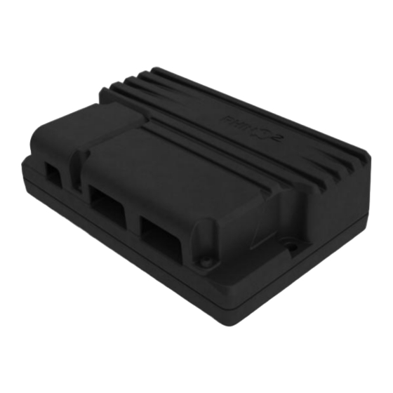
- Page 7 A separately available aluminium terminal cover provides increased protection to IP55 when fitted Compliant with EU Directive 2002/95/EC of 27 Jan. 2003 – restrictions on use of Hazardous Substances (RoHS) Optional single actuator output (with Wig-wag or dedicated switch activation). Chapter 1: Introduction to the RHINO2...
- Page 8 Note: Unless otherwise specified, all references in this manual apply to all variants of the R 2 controller. HINO Chapter 1: Introduction to the RHINO2...
- Page 9 2. Specifications Electrical Specifications Parameter Description Compatible Battery 24V supply, 2 x 12V in series, circuit breaker protected Supply Compatible Motor 24V DC permanent magnet type, typically rated 200-1000 watts. Nominal Units Operating Voltage ( V batt Reverse Supply Voltage Quiescent Current (idle) Quiescent Current (sleep) Quiescent Current (Key-Off)
- Page 10 Warning: The Peak Currents indicated above are for a MINIMUM of 180 seconds @ 20°C ambient when Stall Timeout is set to zero. The installer must ensure that the scooter’s wiring, connectors, and motor will not be damaged if the duration of these high currents is exceeded.
- Page 11 3. Installation and Testing Mounting 3.1.1 General Mounting Conditions 2 Mounting Configuration HINO The position and orientation should give maximum mechanical protection to the controller. Mount out of the path of water splashes from wheels or cowling and protect the connector panel from direct splashing.
-
Page 12: 3.1.2 Mounting Orientation
3.1.2 Mounting Orientation Recommended Mounting Orientation: The recommended mounting orientations for R 2 units are vertical (with connector HINO side on the bottom) and horizontal (with connector facing upwards or downwards). The horizontal (with connector facing downwards) mounting orientation is permitted to be tilted a further 30°... - Page 13 Not Recommended Mounting Orientation: The horizontally tilted mounting orientations and vertical (with connector side on the top) orientation, which have chances of water and dirt accumulation, are not recommended. Horizontally Tilted Mounting Orientations Vertical (Connector side on the top) Mounting Orientation Attaching the terminal cover An optional terminal cover is available for the R 2 controller.
- Page 14 Connections and Wiring 3.3.1 General Wiring Recommendations To maximise performance, minimise EMC emissions, maximise EMC and ESD immunity, and to keep the cabling of the scooter safe and tidy, please observe the following guidelines. Keep all cables as short as possible. Avoid wire loops, especially loops of single wires instead of wire pairs.
- Page 15 For best electrical performance, the wire size must be as large as possible. Recommended minimum wire sizes are shown in the wiring sections. For low-current signals, do not use wire sizes smaller than 0.5mm /AWG20, because smaller wires are physically not strong enough for this application. Make sure that only supplied terminal screws are used.
- Page 16 3.3.2 Wiring Diagram for DS90 and DS120 3.3.3 Wiring Diagram for DS160 Warning: The fuses shown in these diagrams should be located as close to the controller as is practical to minimise the length of unprotected cables. Chapter 3: Installation and Testing...
- Page 17 3.3.4 Wiring Diagram for DS90-ACT and DS120-ACT 3.3.5 Wiring Diagram for DS160-ACT Warning: The fuses shown in these diagrams should be located as close to the controller as is practical to minimise the length of unprotected cables. Chapter 3: Installation and Testing...
- Page 18 (2 x 10AWG) Note: Images shown are for the –ACT units. Position of battery terminals for non –ACT units are identical. Mating Connector Part Numbers DS90, DS90-ACT, DS120, DS120-ACT Dynamic Part # Part Description Supplier Part # 6W Housing 250 Series Plug...
- Page 19 Warning: A thermal circuit breaker or fuse must be installed between the battery supply and the controller, to protect both the batteries and the system wiring. This shall be mounted as close as possible to the battery terminals as per ISO7176-14 requirements.
- Page 20 (2x10AWG) Note: Images shown are for the –ACT units. Position of motor terminals for non –ACT units are identical. Mating Connector Part Numbers DS90, DS90-ACT, DS120, DS120-ACT Dynamic Part # Part Description Supplier Part # 4W Housing 250 Series Plug...
- Page 21 3.5.1 Motor Protection To prevent the motor from overheating, the motor protection function can reduce the performance of the scooter when the motor consumes too much power for a prolonged period. In order to provide adequate protection, the R 2 will remember the condition of HINO the motor when it has been turned off.
- Page 22 Park Brake Connections Park Brake Connections Function Wire Gauge Park Brake Negative 0.5mm / 20AWG Park Brake Positive Mating Connector Part Numbers Dynamic Part Description Supplier Part # Part # Molex „Mini-Fit Jr‟ 2-socket GCN0884 39-01-3028 housing Molex „Mini-Fit Jr‟ Receptacles...
- Page 23 Alternative Park Brake Wiring using a mechanical release lever Alternatively, a normally closed micro-switch can be placed in series with the park brake. This will cause a Flash Code 5 to be displayed and the scooter will be unable to drive. To clear the fault, engage the park brake and turn the power off and then on again.
-
Page 24: Multi-Function Input
Battery Negative 18AWG) 1.0mm² (16- Battery Positive 18AWG) [no connection] 0.5mm² (18- Multi-function Input/Program (P/I) 20AWG) Mating Connector Part Numbers Dynamic Part Description Supplier Part # Part # GCN0886 Molex „Mini-Fit Jr‟ 4-socket housing 39-01-3048 Molex „Mini-Fit Jr‟ Receptacles GCN0776 39-00-0212 16AWG (0.8 –... - Page 25 3.7.1 Battery charger connections There are two options for connecting a battery charger, either on-board (OBC) or off-board. For examples of wiring, see below. If an on-board charger is installed, it is recommended to plug it directly into the Charge/Program connector. For either charging solution, a battery charger with a maximum rating of 8A RMS should be used.
- Page 26 Example of Charger Socket wiring for an Off-board charger (shown using the tiller connector) Note: The inhibit pin is a Multi-function input and can be used for an alternative function if a charger is not plugged into this pin. Warning: A suitable fuse, with a maximum rating of 8A, must be installed in the Battery Positive wire to protect the scooter’s wiring.
- Page 27 3.7.2 Programmer Connections Pin 14 of the Tiller Connector and pin 4 of the charging/programming connector can both be used for programming the R 2. Charging and programming cannot occur using the HINO same inhibit pin at the same time. The R 2 programming adapter will plug directly into an off-board charger socket or into HINO...
- Page 28 If the actuator is driven by a Wig-wag for a period exceeding the Actuator Time- Out (4.4.8.2) the RHINO2 will indicate, with a flash code, an OONAPU condition. This is a transient condition, and the fault is cleared by releasing the Wig-wag, so that it returns to the neutral position.
- Page 29 Actuator connector DS90-ACT, DS120-ACT and DS160-ACT (with actuator) Actuator Output A Actuator Output B Mating Connector Part Numbers Dynamic Part # Part Description Supplier Part # GCN1282 Crimp terminal female spade 18- 2-520407-2 22AWG red insulated Actuator Output Power is supplied to the actuator through Pin 1 (Actuator Output A) and Pin 2 (Actuator Output B) of the actuator connector.
- Page 30 Multifunction Input Pin 6 Act Output B Act Output A Battery Battery + Actuator Connector 14 Way Connector Drive Key Switch Seat/Drive Seat Select Switch Actuator Chapter 3: Installation and Testing...
- Page 31 Multi-function Output (none) Multi-function Input (Reverse Drive) 1.0mm² Battery Negative (B-) (18AWG) 0.5mm² Multi-function Input (Charger Inhibit) (20AWG) Mating Connector Part Numbers Dynamic Part Description Supplier Part # Part # GCN0887 Molex „Mini-Fit Jr‟ 14-socket housing 39-01-2145 Molex „Mini-Fit Jr‟ Receptacles GCN0776 39-00-0212 16AWG (0.8 –...
- Page 32 3.10.1 ISO7176-14 2008 requirements The ISO7176-14 standard requires that the scooter does not start to drive when the throttle circuit is faulty or not calibrated correctly. To comply with this standard, Dynamic Controls‟ 2 controller provides 'Dual Decode' functionality. HINO...
- Page 33 3.10.2 Single throttle wiper Connect the throttle potentiometer ends to T+ (Throttle Positive, pin 2) and T- (Throttle Negative, pin 8). Connect the throttle wiper to TW (Throttle Wiper, pin 1). 5 kΩ To use this option, set the Throttle Input parameter (4.4.2.2) to 'Single'. Warning: If the throttle potentiometer is powered externally (not by T+ and T-), take extreme care to avoid ground shift.
- Page 34 3.10.3 Neutral Detect The Neutral Detect function can be used in addition to a classic single wiper throttle to check whether or not the throttle is in the physical neutral position. If the throttle signal does not match the Neutral Detect signal, the controller generates a fault and does not drive. This makes sure that the scooter will never drive if the throttle wiring is faulty.
- Page 35 3.10.3.1 Installation of a Neutral Detect switch To detect the physical neutral position of the throttle potentiometer, many options are possible. Two options are shown here. Disk with micro-switch Mount a disk to the potentiometer shaft. The disk must have a notch, in which the roller of a micro-switch will fall when the throttle is in the neutral position.
- Page 36 3.10.4 Two throttle wipers - mirrored The R 2 supports the use of a 2x 10kΩ dual gang throttle with 2 linear wiper signals that are HINO each other's opposite. The throttle can either be a short travel or long travel variant. Normal range of travel T+ (Pin 2) Short Travel...
- Page 37 3.10.6 Speed Limit Pot Connections A speed limit pot may be connected either in series with the throttle wiper, or in parallel by using the dedicated input Pin 9 (Speed Limit Pot wiper), Pin 2 (Throttle Positive) and Pin 8 (Throttle Negative).
- Page 38 reduced, use the 'Speed Scale' parameters and leave the 'Speed Limit' parameters at 100%. Chapter 3: Installation and Testing...
- Page 39 3.10.7 Alternative Speed Reduction Options In addition to the throttle and speed limit pot, the R 2 has other speed reduction options HINO to allow for further flexibility in the way speed reduction is applied. For specific details about each of these options, please refer to the programming section: Option Description Profile 2...
- Page 40 Slow Slows the scooter to a set speed limit (a percentage of the maximum speed). Has no effect on scooter acceleration or deceleration. Available on Tiller Connector Pins 4, 6, 12, and 14 and Charger/Programmer Connector Pin 4. Slow/Stop This function has three states: Inactive, Slow and Stop. When Slow is active, the scooter will slow to a programmed speed limit (a percentage of the maximum speed).
- Page 41 3.10.9 Key Switch Input Pin 5 of the tiller connector provides the key switch power circuit. A high quality key switch (>50,000 operations) should be used. Up to 2 status LEDs (up to 10mA each) may be wired in line with this output as an alternative to using one of the Status output pins. Key Switch Key Switch with one Key Switch with two...
- Page 42 “LED Battery Gauge” wiring shown on the right. The algorithm used is the same as the Dynamic Shark power chair controller and has built-in filters to adjust for voltage dips under load and floating voltages after periods of idling.
- Page 43 3.10.13 Brake and Reversing Lights Pin 3 and Pin 11 on the tiller connector can be configured as either a brake light or reversing light. Either light output may be connected to an LED array (500mA) or relay-driven incandescent or halogen bulb. If an LED array is used, it must be a 24V array and have its own internal current limiting system.
- Page 44 3.11 Multi-function Pins The Multi-function Pins maximise flexibility in both scooter design and installation. Allowing the ability to be configured as one of multiple functions, scooter variations typically implemented through wiring changes can now be implemented through programming. The R 2 offers both Multi-function Input and Output pins.
-
Page 45: Actuator Control
The configurable options for each input pin are: Active – This defines the circuit state at which the function operates Slows to – If a Slow function is active, this is the speed the scooter will be limited to Latches –... - Page 46 3.11.1.1 Active States If a pin is in its active state, the corresponding function will be executed. The input pins can be set to the following active states: Input is active when pulled down, inactive when open or pulled up High Input is active when pulled up, inactive when open or pulled down Open...
- Page 47 3.11.1.2 Slows to The Slows to parameter sets the speed to which the controller slows down when a Slow function is active. If set to 0%, the controller will decelerate at the programmed Emergency Deceleration rate and apply the park brake. If set to 100%, the Slow function will have no effect.
-
Page 48: Multi-Function Output
3.11.2 Multi-function Outputs The Multi-function Outputs will output signals dependent on the condition of the controller or batteries. As with the Multi-function Inputs, the Multi-function Output pins have been designed to offer maximum flexibility in the implementation of the scooter feature set and are programmable using the Wizard. - Page 49 3.12 Testing To ensure that each scooter meets a minimum level of safety, the following procedure should be undertaken. This procedure should be carried out in a spacious environment and with due regard to any possible unexpected scooter movement in the event of faulty installation. Raise the wheels off the ground using blocks under the scooter frame so that the wheels can turn freely.
- Page 50 The standard 3-pin XLR-type Battery Charger socket (if available on the scooter) The Charger/Programmer socket on the R 2 itself. HINO DWIZ-ADAPT DX-HHP or Wizard Programming Adaptor. DR-PRGLM02 Connector Adaptor Programming socket Adaptors needed XLR Charger socket DWIZ-ADAPT Charger/Programmer socket DWIZ-ADAPT + DR-PRGLM02 Chapter 4: Programming the Rhino2...
- Page 51 D I A G T E C H Programming Diagnostics Technician Menu Menu Menu The following sections describe the menus of the HHP and give a parameter listing if applicable. Programming menu, 4.1.1 Diagnostics menu, 4.1.2 Technician menu, 4.1.3 Chapter 4: Programming the Rhino2...
- Page 52 For each drive profile, the following parameters can be adjusted: Parameter Section Maximum Forward Speed 4.4.3.1 Forward Acceleration 4.4.3.2 Forward Deceleration 4.4.3.3 Maximum Reverse Speed 4.4.3.4 Reverse Acceleration 4.4.3.5 Reverse Deceleration 4.4.3.6 Minimum Forward Speed 4.4.3.7 Minimum Reverse Speed 4.4.3.8 Chapter 4: Programming the Rhino2...
- Page 53 4.4.1.3 Higher settings make the Battery Capacity battery gauge react slower. Service Scheduler (Service Period) 4.4.8.1 Beep on Fault (Flash Code Beeper) 4.4.1.5 Beep on Sleep (Sleep Beeper) 4.4.1.6 Reversing Beeper 4.4.1.7 Motion Beeper 4.4.1.7 Chapter 4: Programming the Rhino2...
- Page 54 If the 'Return to Neutral' screen does not appear, the calibration procedure was started while a fault was active. Press EXIT to cancel the calibration procedure, eliminate the fault and start the calibration procedure again. 6. Release the throttle to its neutral position. Chapter 4: Programming the Rhino2...
- Page 55 E X I T N E X T R E T R Y Calibrate again Main Next Option (Prof 1/2, Non-Profiled) Menu If this happens, press RETRY to repeat the calibration from the start, and go back to step 4. Chapter 4: Programming the Rhino2...
- Page 56 Wizard shows the values that have been stored the last time that the unit was turned off. For this reason, the usage counters shown in the Wizard are usually slightly lower than the values shown in the HHP. Chapter 4: Programming the Rhino2...
- Page 57 Also, the following parameters can be read real-time: Parameter Typical Battery Voltage 23 - 28 V Motor Voltage 0 - Battery Voltage Motor Current 0 - unit rating Controller Temperature 10 - 80 degrees Throttle Voltage 0 - 5 V Chapter 4: Programming the Rhino2...
- Page 58 Dynamic Wizard The PC-based Dynamic Wizard provides access to the all parameters that are allowed to be edited or seen based on the dongle level. In addition, the Wizard can also generate comprehensive diagnostics reports. For more information, see the Wizard user manual.
- Page 59 No / Yes Slam Brake Enable No / Yes Slam Brake Threshold 0 - 100 % 40 % Enable SRW Open Circuit Testing No / Yes Chapter 4: Programming the Rhino2...
- Page 60 SRW Reverse Speed Limit 0 - 100 % 50 % SRW Reverse Speed Scale 0 - 100 % 50 % SRW Scaling Resistor (Ohm) 400 - 25500Ω 3200Ω Chapter 4: Programming the Rhino2...
- Page 61 DS120, DS160: DS120, DS160: DS90: DS120: Boost Time DS160: Stall Timeout 0 - 51s None Open Motor Testing Short Short Maximum Motor Voltage 0 - 64V 26.2V Chapter 4: Programming the Rhino2...
- Page 62 Status Pin 11 Function Power Status Power Status None Status High Status Low Pin 10 Function Status High 5V Gauge 12V Gauge Other Key Switch Status LED No / Yes Chapter 4: Programming the Rhino2...
- Page 63 Key + Throttle - The key switch as well as any throttle movement wakes up the controller. Note: If the value of Sleep Timer is zero, the value of Wakeup Style is ignored. Chapter 4: Programming the Rhino2...
- Page 64 This parameter is only used when Enable Beeper has the value 'Yes'. If a flash code is shown on the Status LED, the buzzer beeps the same number of beeps as the flash code number. The buzzer does not beep during a fault. Chapter 4: Programming the Rhino2...
- Page 65 Possible Values Default Lite Beeper On Time 100 – 1500ms 300ms Beeper Off Time 0 – 1500ms 700ms These parameters are only used when Enable Beeper has the value 'Yes'. Chapter 4: Programming the Rhino2...
- Page 66 4.4.1.12 Power Off after Sleep Parameter Possible Values Default Lite Power Off after Sleep No / Yes Enables powering the unit off automatically after sleeping for approximately 6 hours to save battery power. Chapter 4: Programming the Rhino2...
- Page 67 If the sum of the signals is more than 10% lower or higher than the expected maximum value, the scooter stops and a throttle fault is shown on the Status light. Chapter 4: Programming the Rhino2...
- Page 68 50% to make sure that the scooter can still reach maximum speed. Neutral Mechanical Mechanical Offset stopper Voltage Voltage stopper 2.5V Full Scale Full Scale Deflection Deflection set to 50% set to 50% 0 - 100% Throttle range Chapter 4: Programming the Rhino2...
- Page 69 100% = (Maximum Throttle Voltage - 0%)/2 + 0% (halfway between 0% value and Max V) Min V NOx2 Halfway valid range = 100% Max V 0 - 100% DB Fault Fault Throttle Dead Band range for Single-ended setups Chapter 4: Programming the Rhino2...
- Page 70 If Throttle Testing is set to 'Yes', and the voltage at the throttle wiper input is more than 10% higher than Maximum Throttle Voltage or 10% lower than Minimum Throttle Voltage, the controller generates a throttle fault to indicate that an error may have occurred with the throttle or its wiring. Chapter 4: Programming the Rhino2...
-
Page 71: Oonapu
Only set this parameter to 'Yes' for testing purposes. If throttle faults are non-latching, the scooter immediately starts to drive at the speed that the throttle is held at when a throttle fault disappears. This can easily happen with a throttle that is not calibrated correctly. Chapter 4: Programming the Rhino2... - Page 72 Lowest FWD Speed Lowest REV Speed Voltage (pin 9) The throttle output is scaled down, not limited, so the throttle does not have a dead band when the speed pot is at a low setting. Chapter 4: Programming the Rhino2...
- Page 73 Testing When Enable SRW Open Circuit Testing is enabled, a fault will be generated when the SRW resistor is disconnected. This is useful for detecting open circuit faults (e.g. broken wire) in the SRW circuit. Chapter 4: Programming the Rhino2...
- Page 74 Note: This parameter cannot be set higher than the value of the Maximum Forward Speed Limit parameter (4.4.4.1) that has been set by the scooter manufacturer. Chapter 4: Programming the Rhino2...
- Page 75 Note: This parameter cannot be set higher than the value of the Acceleration Limit parameter (4.4.4.5) that has been set by the scooter manufacturer. Chapter 4: Programming the Rhino2...
- Page 76 Setting Forward Deceleration too low or too high can result in a scooter that is unsafe. Test thoroughly after programming to make sure that the scooter complies with local regulatory requirements for maximum allowable braking distance. Chapter 4: Programming the Rhino2...
- Page 77 Note: This parameter cannot be set higher than the value of the Acceleration Limit parameter (4.4.4.5) that has been set by the scooter manufacturer. Chapter 4: Programming the Rhino2...
- Page 78 Forward Speed is not used and Speed Limit Pot must be set to 'No'. This parameter cannot be set lower than the value of the Minimum Forward Speed Limit parameter (4.4.4.3) that has been set by the scooter manufacturer. Chapter 4: Programming the Rhino2...
- Page 79 Higher values give a softer start, while lower values give a more direct and harsh start. To disable soft start completely, set Soft Start Period to zero. Speed Soft-Start Period Time Chapter 4: Programming the Rhino2...
- Page 80 If the normal deceleration rate is higher than Emergency Deceleration, the normal deceleration value is used. Warning: If this parameter is set too high, the user can fall out of the scooter during an emergency stop. Chapter 4: Programming the Rhino2...
- Page 81 (see 4.4.9) to 'Release Brake'. Warning: To meet ISO requirements, the scooter must not be able to drive when the park brake is released. Do not operate the park brake release while on a slope. Chapter 4: Programming the Rhino2...
- Page 82 If Pin 4 Function is set to 'SRW (variable)' and the resistance is the value of SRW Scaling Resistor (Ohm) or more, the speed is not reduced. If the resistance is zero, the speed is reduced to the value of any of the four SRW Speed parameters. Chapter 4: Programming the Rhino2...
- Page 83 5% lower than the actual maximum resistor value connectecd to the pin to allow for component tolerance, otherwise, maximum speed might not be achieved. This parameter is only available for editing if Pin [x] Function, where „x‟ is 4, 6 or 12, is set to SRW (variable). Chapter 4: Programming the Rhino2...
- Page 84 0 - 100 % 100 % Deceleration Limit Sets the maximum value that can be set by a dealer for the Forward Deceleration (4.4.3.3) and Reverse Deceleration (4.4.3.6) parameters. Set to 100 for no effect. Chapter 4: Programming the Rhino2...
- Page 85 Current Limit current before it becomes too hot. If the actual motor current is above Motor Continuous Current but much lower than Current Limit, the time before the motor protection limit is activated is longer. Chapter 4: Programming the Rhino2...
- Page 86 If the Load Compensation parameter is changed after the scooter has been set up, the complete speed/acceleration programming and testing procedure must be repeated. Chapter 4: Programming the Rhino2...
- Page 87 Optimum Load Compensation. Scooter responsive AND smooth Nervous Unresponsive Uncontrollable Aim for this point: 20 % back from the top of the hill Load Compensation Chapter 4: Programming the Rhino2...
-
Page 88: Park Brake Neutral Delay
(Note: this parameter has no effect if the scooter stops and restarts driving quickly such that the park brakes are never applied.) Chapter 4: Programming the Rhino2... - Page 89 The maximum useable setting depends on the current rating for the controller type, for example 90A for the DS90. Higher settings have no effect on the controller. Warning: Do not set this parameter too high for the type of motor used. Chapter 4: Programming the Rhino2...
- Page 90 If a stall timeout occurs, the scooter performs an emergency stop and the Status LED shows Flash Code 4 (see section 5.2 for flash code descriptions). The scooter does not drive. To reset the fault, turn the scooter off and turn it back on again. Chapter 4: Programming the Rhino2...
- Page 91 2 will deliver as much power as it can, for as HINO long as it can, while still protecting itself. This is not recommended because it can be against local regulations and can cause motor damage. Chapter 4: Programming the Rhino2...
- Page 92 (for example when the battery is almost empty), then the battery voltage itself is the maximum applied voltage at 100 % speed demand. The actual voltage output from the R 2 may at times be up to 10V higher than this setting HINO due to Load Compensation (4.4.5.5). Chapter 4: Programming the Rhino2...
-
Page 93: Park Brake Output
If the value of Park Brake Neutral Delay is set too high, there may be too much rollback when stopping on a slope. If the value is set too low, the scooter may stop too abruptly. Chapter 4: Programming the Rhino2... - Page 94 Default Lite Park Brake Release Delay 0 - 25500ms 100ms While stopped, sets the delay between throttle movement and the park brakes being disengaged. Energise Park Brake park brake Release Delay Throttle deflected Chapter 4: Programming the Rhino2...
- Page 95 The scooter will drive slower but should still be able to climb small obstacles such as curbs. If the battery voltage falls below Undervoltage Rollback End, the scooter stops driving because the throttle is reduced to zero. Battery Almost Empty Battery Empty UVR End UVR Start Chapter 4: Programming the Rhino2...
- Page 96 19 - 27V 24.4V Battery Gauge Minimum sets the voltage at which the battery gauge indicates an empty battery. Battery Gauge Maximum sets the voltage at which the battery gauge indicates a full battery. Chapter 4: Programming the Rhino2...
- Page 97 Battery Gauge Dead-band makes sure that the battery gauge only shows a higher charge when the battery is actually being charged. Any increase in battery voltage that is lower than the value of Battery Gauge Dead-band is ignored. Chapter 4: Programming the Rhino2...
- Page 98 5% after Battery Gauge Sensitivity x 1.5 seconds. The 100% range of the battery gauge falls between Battery Gauge Minimum and Battery Gauge Maximum. For better battery gauge accuracy, increase the value of Battery Gauge Sensitivity with high capacity batteries and decrease the value with low-capacity batteries. Chapter 4: Programming the Rhino2...
- Page 99 Actuator Time-Out parameter sets the Actuator Time-Out variable between 0 and 60s. The scooter will stop powering the actuator after Actuator Time-Out has occurred. To restart powering the actuator, release the control, and start driving the actuator again. Chapter 4: Programming the Rhino2...
-
Page 100: Pin [X] Function
If multiple pins are programmed to perform Reverse Drive, they work in parallel: reverse drive applies as long as any combination of one or more pins is activated. Available on all input pins. Chapter 4: Programming the Rhino2... - Page 101 Light will show a "Drive Inhibit" flash code while the drive inhibit is active. See section 5.2 for more information on flash codes. Only valid Active settings are 'High' and 'Low', all other settings disable the input (the input will never become active). Available on all input pins. Chapter 4: Programming the Rhino2...
- Page 102 For the three Slow/Stop functions, the Latches and Flashes parameters have no effect if Throttle OONAPU Testing (4.4.2.9) is set to Latching. If Actuator Control and Actuator Wig-Wag are programmed, the controller only executes Actuator Control; Actuator Wig-Wag is ignored. Chapter 4: Programming the Rhino2...
- Page 103 Input is inactive when pulled up, active when open or pulled down High or Open Input is inactive when pulled down, active when open or pulled up To pull up an input, connect it to B+. To pull down an input, connect it to B-. Chapter 4: Programming the Rhino2...
- Page 104 * The Scooter and R-Series produce the same flash code sequences to indicate a fault, but the flash timings are different: Scooter flash timings: 250ms ON / 500ms OFF with a 2s break between. R-Series flash timings: 140ms ON / 400ms OFF with a 2.4s break between. Chapter 4: Programming the Rhino2...
- Page 105 When using the HHP to program, use both the Motion Beeper and the Reversing Beeper parameters, as set out in the table below. Motion Beeper Reversing Beeper Wizard Equivalent Reverse None None Forward/Reverse Chapter 4: Programming the Rhino2...
- Page 106 If this is the case, resistors mounted in parallel to the LED array may reduce the glow. For more information and schematics, see Status Indicator Output (section 3.10.10), Beeper Output (section 3.10.11) and Brake and Reversing Lights (section 3.10.13). Chapter 4: Programming the Rhino2...
- Page 107 Parameter Possible Values Default Lite Key Switch Status LED No / Yes To reduce current drain, set this parameter to 'No' if a status LED is not wired in series with the key switch. Chapter 4: Programming the Rhino2...
- Page 108 5. Diagnostics Note: The R 2 is not user serviceable. Specialised tools are necessary for the repair HINO of any R 2 component. HINO Introduction An abnormal condition may be indicated by a flash code on the Status output. A Flash Code is a sequence of flashes, separated by a pause, followed by a repetition of the sequence.
- Page 109 5.2.1 Scooter / R-Series Flash Codes* Flash Description Meaning Battery Low The batteries are running low or are in an over- discharged state. Recharge the batteries. Low Battery Fault The batteries have run out of charge. Recharge the batteries. Check the battery and associated connections and wiring.
- Page 110 5.2.2 SHARK Flash Codes Flash Description Meaning User Fault / Drive Inhibit Either a Stop function is active or a Charger Inhibit condition has occurred. Release the Stop condition (seat raised etc.) Disconnect the Battery Charger • Turn the controller off and then on again. Battery Fault Battery voltage is either too low or too high.
- Page 111 5.2.3 Type 3 Flash Codes Flash Description Low Battery Bad Motor Connection Motor Short Circuit Current Limit Time-out / Controller too hot unused Drive Inhibit Throttle Fault Controller Fault Park Brake Fault High Battery Voltage 5.2.4 Type 4 Flash Codes A Type 4 flash code involves the use of twin flashes to identify the type of fault.
- Page 112 When the hand held programmer is plugged in, it will display a flash code 9 on the screen. DYNAMIC Wizard Wizard is the preferred diagnostics tool in the workshop environment, providing a full fault history (last 16) and verbal descriptions of each flash and associated servicing code.
- Page 113 Possible motor short circuit o check the motor cables for damage o Motor brushes may be too stiff and bouncing Otherwise internal controller fault, contact Dynamic Controls Intermittent short circuit Check for damaged cables Motor brushes may be too stiff, bouncing against the case...
- Page 114 Battery gauge fault, battery gauge deactivated Check if the battery gauge cables are damaged or loose Rollaway The scooter moved too fast when the park brakes were released Turn the scooter off and back on again Internal fault Contact Dynamic Chapter 5: Diagnostics...
- Page 115 Advanced Diagnostics Logs In addition to the standard diagnostics reports, additional diagnostic information is available from the controller using the Wizard or HHP. This additional information is extremely useful for identifying the root cause of any faults, and allows for a faster, more efficient service process. It will also allow for feedback to be given to the user if their use of the scooter is causing any issues.
- Page 116 Service Scheduler The Service Scheduler is a preventative maintenance feature that allows the OEM to set up scheduled servicing plans for their scooter customers. If enabled, a Service Period can be programmed into the controller. Once the Drive Time exceeds this value, the status LED will flash slowly 3 times every time the scooter is turned on or wakes up from sleep, to indicate the service is due.
- Page 117 6. Appendices Neutral Detect Active States The following options are available to setup a Neutral Detect circuit. Active Switch in Switch Neutral Driving Short Short circuit Open Open wire State Neutral connected circuit in while driving wire in while driving Neutral neutral Closed...
- Page 118 Accessories + Parts List Dynamic R 2 Installation Manuals HINO Part Description DCL Part # Qty/Unit Dynamic R 2 Installation Manual HINO GBK51948 Dynamic R 2 Connectors HINO Part Description DCL Part # Qty/Unit Flammability (UL 94) DS90 Motor/Park brake Adaptor Loom...
- Page 119 2 Programming Accessories HINO Part Description DCL Part # Qty/Unit Wizard Kit – Programming Kit Contains DWIZ-KIT software, cables and adapter (no dongle) Dynamic Wizard Programming Adapter DWIZ-ADAPT Molex Programming Adapter DR-PRGLM02 Serial to USB Adaptor DX-USB-COM PCD Cable Assembly DWIZ-CABLE Wizard Dongles –...
- Page 120 Intended Use and Regulatory Statement Intended Use The R 2 scooter controller is intended to provide speed control for small, medium or large HINO sized scooters that utilise a single 24V DC brushed motor and integrated park brake. The 2 with Seat Lift (DS90-ACT, DS120-ACT and DS160-ACT) controllers are also fitted with a HINO seat actuator control that is used to adjust seat height through a DC motor driven seat actuator.
- Page 121 Warranty All equipment supplied by Dynamic Controls is warranted by the company to be free from faulty workmanship or materials. If any defect is found within the warranty period, the company will repair, or at its discretion replace, the equipment without charge for materials or labour.
- Page 122 Safety and Misuse Warnings Warnings to be included in the User Manual The following warnings are applicable to the installer and must be passed on to the end-user before use of the product. Do not install, maintain, or operate this equipment before you have read and understood all the instructions and all the manuals for this product and all the other products that you use or install together with this product.
- Page 123 Dynamic Controls has made every effort to make sure that RFI does not change the behaviour of the controller, but very strong signals can still cause a problem. The vehicle manufacturer has the responsibility to make sure that the vehicle is tested according to local EMC regulations.
- Page 124 Electromagnetic Compatibility (EMC) Dynamic Controls Electronic Controllers have been tested on typical vehicles to confirm compliance with the following appropriate EMC standards: USA: ANSI/RESNA WC/Vol:2 - 1998 Sec 21 Europe: EN12184:2009 Sec 9.1 National and international directives require confirmation of compliance on particular vehicles.
- Page 125 Minimum Reverse Speed Limit ......84 Drive Time ............115 Minimum Throttle Voltage ........70 Dual Decode ........... 32, 37 Motion Beeper ............. 65 DYNAMIC Wizard ..........112 Motor (A) ............115 Motor (V) ............115 Motor Continuous Current ........85 EMC Emissions ............. 14...
-
Page 126: Table Of Contents
Motor Cooling Time ..........85 Pin 4 Function ..........100 Motor Heating Time ..........85 Pin 6 Function ..........100 Motor Negative (M-) ..........20 Prog/Inh Pin Function ........100 Motor Positive (M+) ..........20 Pin 10 Function ..........107 Motor Protection ........... - Page 127 Sleep Beeper ............65 Throttle Wiper ..........31, 33 Sleep On Fault Or Inhibit ........66 Tiller Connector..........27, 31 Sleep Timer ............63 Tiller Head ............31 Slow ..............101 Type 3 Flash Codes Slow/Stop ............101 Bad Motor Connection ........111 Slow/Stop FWD ..........
- Page 128 Dynamic Controls was established in 1972 and is headquartered in New Zealand. Regional centres are located in Europe, United States, Asia, and Australasia. ISO 13485 certified – Dynamic Controls goes above and beyond industry standard expectations to ensure customers receive the best products possible.
Need help?
Do you have a question about the RHINO2 and is the answer not in the manual?
Questions and answers