Table of Contents
Advertisement
Advertisement
Table of Contents

Related Manuals for Dynamic DX Series


Summary of Contents for Dynamic DX Series
- Page 1 DX-GB Gearless Brushless Installation Manual GBK64947 Issue 1,June 2007...
- Page 2 About this Manual This manual has been designed to help you install and configure a Dynamic DX-GB powerchair control unit for a ‘generic’ brand powerchair. For this reason there are no guidelines for specific applications. This manual must be read in conjunction with all other relevant DX-System manuals.
- Page 3 All other brand and product names, fonts, and company names and logos are trademarks or registered trademarks of their respective companies. Dynamic owns and will retain all trademark rights and Dynamic or its licensors own and will retain all copyright, trade secret and other proprietary rights, in and to the documentation.
-
Page 4: Table Of Contents
Contents Introduction.............7 The DX system..................7 The DX-GB Gearless Brushless controller ........... 8 Installation and Testing ........10 DX-GB Mounting ................. 10 Connections and Wiring..............11 2.2.1 Cable and Connector Pin-outs..........12 2.2.2 Battery Connections .............. 12 2.2.3 Motor and Park Brake Connections........14 2.2.4 DX BUS Connections .............. - Page 5 Appendices ............43 Programming Accessories..............43 Intended Use and Regulatory Statement ........44 Maintenance..................45 Warranty....................46 Safety and Misuse Warnings ............. 47 Electromagnetic Compatibility (EMC)..........49 Environmental Statement..............50...
- Page 6 : Issue 1 – June 2007 GBK64048...
-
Page 7: Introduction
1 Introduction 1.1 The DX system DX is a modular, expandable power wheelchair control system. This modularity allows the system to be expanded and customized to particular end-user needs and handles the requirements from basic driving to full environmental control. A power module and a master remote are required along with a DX BUS cable to form the base of any DX system. -
Page 8: The Dx-Gb Gearless Brushless Controller
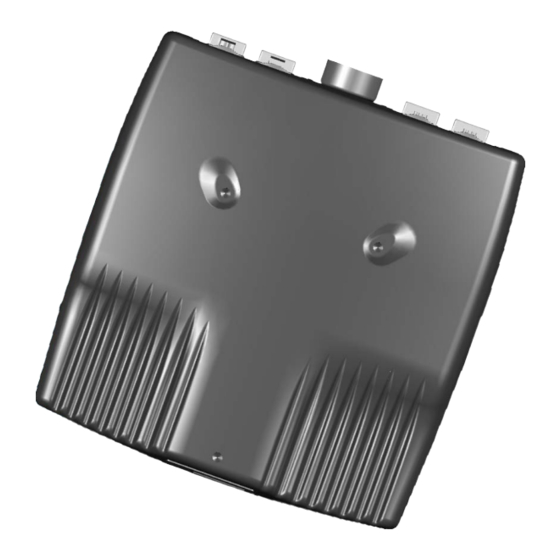
1.2 The DX-GB Gearless Brushless controller The Dynamic DX Gearless Brushless Power Module (DX-GB) is a DX BUS compatible module that converts signals generated by a DX Remote into high current outputs. These outputs drive the motors that control the powerchair speed and direction. The combination of a DX-GB and DX Master Remote give an exceptionally smooth, powerful, and safe drive system. - Page 9 DX-GB Power Module Motor Motor G90 or G91 Charger Drive Control Input Other DX module Programmer (HHP or PC) Alternative On-board Other DX Battery Charger module 24V Battery...
-
Page 10: Installation And Testing
2 Installation and Testing 2.1 DX-GB Mounting M5 x 10mm or #10/32 x 0.39" (max) TYP x 3 74 mm 2.91" The DX-GB must be mounted with the lid-down and at a minimum incline of 5° from horizontal. 5° min, 90° max The position and orientation must give maximum mechanical protection to the DX-GB. -
Page 11: Connections And Wiring
For peak performance, locate the DX-GB so that air can flow over and around the case. Make sure that the mounting position minimizes bending and flexing stresses on the motor cables, especially with moving motor/wheel suspension. Use all three mounting points to attach the DX-GB. The use of M5 or #10/32 screws that engage up to 10mm/0.39"... -
Page 12: Cable And Connector Pin-Outs
2.2.1 Cable and Connector Pin-outs To Motor 1 (left) To Motor 2 (right) All connectors viewed from front. Pin numbers are for reference only. Actual pin numbers on mating connector housings may differ from those given below. Battery Cable Connector Pin-out Function Battery Negative (Black) Battery Positive (Red) - Page 13 The final connection to the Battery Positive (+) terminal must not be made until the powerchair is completely wired and ready for testing as described in the Testing section. The DX-GB has been designed to perform optimally with either Lead- Acid or Gel Cell 24 V deep cycle batteries. Ensure that the battery capacity and the battery charger rating are sufficient to not restrict the high performance needs of the system.
-
Page 14: Motor And Park Brake Connections
2.2.3 Motor and Park Brake Connections The DX-GB has two motor cables (left and right) that plug directly into the motors. Programming note: You can program the DX-GB to swap the motor connections, if necessary. 2.2.4 DX BUS Connections The DX-GB communicates with the rest of the DX system through the DX BUS. The DX BUS also supplies power to every other DX Module. -
Page 15: Drive Control Input (Dci) And Obc Connections
2.3 Drive Control Input (DCI) and OBC Connections The DX-GB provides support for an On-board Battery Charger (OBC), an ‘inhibit’, and a ‘speed limit’ function (either digital or analog) through the Drive Control Input (DCI) socket as shown to the right. The On-board Battery Charger supports up to 12 Amperes (RMS) directly through the connector. -
Page 16: Dci - Analog Mode
2.3.1 DCI – Analog Mode When the Digital Input setting is set to ‘No’, the DCI will limit the drive speed of the chair to a value proportional (linear) to the resistance of the DCI Loop, typically through use of an analog potentiometer. A loop resistance of 220 ohms will have no effect on the chair speed, while a value of 56 ohms will cause the chair to slow down to the value set in Reduced Speed. - Page 17 Example 2 A powerchair has a seat raise function and an On-board Battery Charger (OBC). The DX-GB will automatically limit the speed by an amount proportional to the seat height, and inhibit drive when the OBC is plugged in. When plugged in, an internal switch in the OBC will activate causing a closed circuit (<10 ohms).
-
Page 18: Motor Calibration
3. Make the final connection to the Battery Positive (+) terminal and close the circuit breakers. Note: If the used master remote is not pre-programmed with the intended chair program, download the program for this chair with the Dynamic Wizard. : Issue 1 – June 2007 GBK64048... - Page 19 4. Press the Power button to turn the DX system on. Ensure it turns on correctly. Note: The first time the DX Master Remote is turned on, the System Status LED will flash a fault. This is because the DX Master Remote must download its information to the DX-GB.
-
Page 20: Programming
3 Programming Warning: Performance adjustments should only be made by professionals in the health care field or by persons fully conversant with the adjustment process and the user’s capabilities. Incorrect settings, or programming in an unsafe location, can cause injury to the operator or bystanders, or damage to the vehicle or surrounding property. -
Page 21: Description Of Parameters
Note: The Wizard needs the DX-GB database update to recognize the DX- GB. Make sure you have the latest version of the Wizard database installed. The latest version is available for download on the Dynamic website: www.dynamiccontrols.com. Warning: Always test the vehicle after programming to ensure that the intended operation is achieved. -
Page 22: Modified System Drive Parameters
3.2.1 Modified System Drive Parameters Setting Description Drive Profiles Sets the maximum forward speed for the selected profile when the selected joystick is pushed fully forward. Set to a low value for a Forward Speed @ lower maximum speed, for example when setting an indoor driving Maximum profile. - Page 23 Setting Description Drive Profiles Sets the maximum turning speed for the selected profile when the selected joystick is pushed fully left or fully right. Set to a low value Turning Speed @ for a slower controlled wheelchair drive performance particularly Maximum when driving indoors.
-
Page 24: Dx-Gb Specific Parameters
3.2.2 DX-GB Specific Parameters Setting Description Joystick How non-linear the speed response is to the joystick position, Joystick Speed with 0 giving a linear response. This has no effect on the Progression maximum speed. Used to allow fine low-speed control. How non-linear the turning response is to the joystick position, Joystick Direction with 0 giving a linear response. - Page 25 Setting Description Drive Performance Sets the accuracy of the control loop response at higher speeds. Higher values give more precise control but may feel True-Track (Torque) harsh and require more power from the battery. Dampens (or softens) the chair reaction to joystick commands. Tremor Range Higher values give smoother but less responsive drive performance.
- Page 26 Setting Description Battery Changes the battery level gauge display to use a voltmeter Voltmeter Battery style display rather than the standard battery gauge which tries Gauge to determine the battery capacity. When using the voltmeter-style battery gauge, enabling this Slow Batt Time Scale parameter will lessen the responsiveness of the gauge, Driving damping down any voltage ‘wavering’.
-
Page 27: Dx-Gb Parameter Access List
3.3 DX-GB parameter access list 3.3.1 Hand Held Programmer (HHP) parameter list Parameter Joystick Speed Progression Joystick Direction Progression True-Track (Torque) Tremor Range 3.3.2 Wizard parameter access list Key: Editable at this level Lite: Dealer level dongle Std: Enhanced dealer level dongle Viewable at this level ⌧... - Page 28 Wizard Parameter Lite Turning Speed @ Maximum Turning Speed @ Minimum (Turn Damping N/A) Turning Acceleration (Turn Damping N/A) Turning Deceleration Turn Damping Non-Linear Turn Short Throw Shape Short Throw Travel Grip Speed Damping Min to max decel ratio Speed x Turn for Grip Accel out of a Turn for Grip Accel into a Turn for Grip Turning @ Full Speed...
- Page 29 Wizard Parameter Lite System Settings CLAM slowdown Neutral to PB delay Chair Speed Enable Single Profile Mode UCM Joystick Swap Left/Right Rotate UCM Joystick ACU joystick Swap Left/Right RJM joystick Swap Left/Right RJM has analog joystick DX-GB Parameters Joystick Joystick Speed Progression Joystick Direction Progression Max J/S Speed+Dir Drive Control Input...
- Page 30 Wizard Parameter Lite TremorRange Speed Filter Slam Braking Accel Stop Y Accel Stop X Reduced Turn Speed Reduce Turn Start ⌧ ⌧ Reduce Turn Full ⌧ ⌧ Max SpeedTurn ⌧ ⌧ Speed Accel Scaler ⌧ ⌧ Turn Accel Scaler ⌧ ⌧...
- Page 31 Wizard Parameter Lite Voltmeter Battery Gauge Slow Batt Time Scale Driving Batt Gauge Ramp Up Rate Batt Gauge Ramp Down Rate Batt Gauge High Threshold Batt Gauge Falling Threshold High Voltage Warning High Voltage Threshold Motors Invert Speed Motor Direction Swap ⌧...
- Page 32 Wizard Parameter Lite Park Brake Park Brake Test ⌧ ⌧ Park Brake Hold-off Time ⌧ ⌧ Drop-In Current ⌧ ⌧ Lowered Park Brake Current ⌧ ⌧ Park Brake Voltage ⌧ ⌧ Park Brakes Release Time ⌧ ⌧ Park Brakes Drop-in Time ⌧...
-
Page 33: Diagnostics
Wizard is the preferred diagnostics tool in the workshop environment, providing a full fault history and shows any current faults. If, after analyzing the data, the condition cannot be diagnosed, it is possible to print, save or e-mail a Status Report to a Dynamic service centre for further analysis. -
Page 34: Flash Codes
Turn the system Off, wait a few Temperature Fault minutes for the system to cool down, and then turn On again. • If the fault re-occurs, consult your Dynamic Service Centre. Left Motor Fault • Check the left motor, connections and cabling. Right Motor Fault •... -
Page 35: User Advice And Error Codes
Re-program the system. • If the fault re-occurs, consult your Dynamic Service Centre. 4.4 User Advice and Error Codes If there is an abnormal condition specific to the DX-GB, the HHP may display User Advice and/or Error Codes within the DX-GB menu. The standard DX-GB menu will be displayed if there is no Error Code or User Advice found. -
Page 36: User Advice List
4.4.1 User Advice List The different User Advice items are: No advice, call dealer Switch off and on, retry GB controller failure Check left motor/cabling Check right motor/cabling Current calibration jig fault Current limit test failure Control software failure Left motor calibration, retry Right motor calibration, retry Low battery, recharge Check joystick cabling... - Page 37 PComp Exceeded Right Serial Timeout Wrong Id Range Unknown Command Bad Checksum Undervoltage-15 Overvoltage-15 Undervoltage Overvoltage Brake Short Left Brake Short Right Timer-A Bad Timer-B Bad AD Not Starting AD Not Ready AD Wrong Timing Hall Left-0 Error Hall Left-1 Error Hall Right-0 Error Hall Right-1 Error No Current Calibration...
-
Page 38: Specifications
5 Specifications Specifications of the DX-GB controller 5.1.1 Electrical specifications Parameter Description 24V supply (2 x 12V in series), circuit breaker protected, Compatible Battery lead acid or gel cell type of recommended minimum Supply capacity 30 Amp hours. Compatible Motor 24V AC Gearless Brushless. -
Page 39: Physical Specifications
5.1.2 Physical Specifications Parameter Material Die cast Aluminium Finish Powder coated “Rolling Thunder” (Charcoal/Silver) Protection Rating IPx4 Product weight 2.160 kg Shipping Weight 2.560 kg Nominal Units Operating Temperature Range °C Storage Temperature Range °C Operating Humidity Range 185 mm 345 mm Motor L 345 mm... -
Page 40: Specifications Of The Euro Gb Motor
5.2 Specifications of the Euro GB Motor 5.2.1 Electrical and mechanical specifications Note: These specifications are for a typical single motor driven by a Dynamic DX-GB controller powered from a 24V power supply. Motor type Permanent magnet brushless DC with integral brake... -
Page 41: Performance Charts
5.2.2 Performance charts Euro GB Motor Efficiency Speed Efficiency Current Torque [Nm] Euro GB Motor Output Power Speed Power P – Speed limit 10 P – Speed limit 8 P – Speed limit 6 Torque [Nm] Given speed is based on a standard 8" tyre with a nominal outer diameter of 330 mm. -
Page 42: Physical Specifications
5.2.3 Physical specifications Right Motor – WMT9998GB Hub – WHL9999 Left Motor – WMT9999GB Note: "Left Motor" and "Right Motor" only refers to the part number of the motor. The actual mounting and connection (left or right) depends on the design of the powerchair. Parkbrake release direction... -
Page 43: Appendices
6 Appendices 6.1 Programming Accessories Dynamic DX Programming Accessories Part Description DC Part # Qty/Unit Wizard Kit – Programming Kit Contains DWIZ-KIT software, cables and adapter (no dongle) Wizard – Software Only (CD) DWIZ-SW Wizard Dongles – Parallel port OEM/Advanced version... -
Page 44: Intended Use And Regulatory Statement
6.2 Intended Use and Regulatory Statement Intended Use The DX-GB is a component of the DX System intended to provide speed and direction control of dual, compatible 24V brushless motors and release of normally-activated park brakes located on a powerchair. The DX-GB receives input commands from a DX Master Remote. -
Page 45: Maintenance
2. All switchable functions on the Dynamic electronics system must be regularly tested to ensure they function correctly. 3. All Dynamic electronic components must be kept free of dust, dirt and liquids. If necessary, wipe with a cloth dampened with warm water. Do not use solvents or abrasive cleaners. -
Page 46: Warranty
6.4 Warranty All equipment supplied by Dynamic Controls is warranted by the company to be free from faulty materials or workmanship. If any defect is found within the warranty period, the company will repair the equipment, or at its discretion, replace the equipment without charge for materials and labor. -
Page 47: Safety And Misuse Warnings
While Dynamic Controls has made every effort to ensure that RFI does not affect the product performance or safety, very strong signals could still cause a problem. - Page 48 Service and Configuration Warnings The following warnings are applicable to the installation technician only. • Ensure that the battery capacity and the battery charger rating are sufficient to not restrict the high performance needs of the system. Peak performance capability is important to ensure safe control of the wheelchair.
-
Page 49: Electromagnetic Compatibility (Emc)
6.6 Electromagnetic Compatibility (EMC) Dynamic Electronic Controllers have been tested on typical vehicles to confirm compliance with the following appropriate EMC standards: USA: ANSI/RESNA WC/Vol:2 - 1998 Sec 21 Europe: EN12184:1999 Sec 9.8.1-3 National and international directives require confirmation of compliance on particular vehicles. -
Page 50: Environmental Statement
6.7 Environmental Statement This product has been supplied from an environmentally aware manufacturer. Please be environmentally responsible and recycle this product at the end of its life through your local recycling facility. This product may contain substances that can be harmful to the environment if disposed of into a landfill. - Page 52 Contact details Dynamic has a global network of sales and service centres. Please contact your nearest Dynamic representative for Sales and Service advice, or visit our web site: www.dynamiccontrols.com New Zealand – Head Office Australia – Service Agent Dynamic Controls...
Need help?
Do you have a question about the DX Series and is the answer not in the manual?
Questions and answers