
Subscribe to Our Youtube Channel
Related Manuals for rotork Pakscan IIS


Summary of Contents for rotork Pakscan IIS
- Page 1 Pakscan IIS Master Station Technical Manual Publication - S130E Issue 1.0 23 June 1996...
- Page 2 Pakscan IIS Technical Manual Publication S130E Issue 1.0 As we are continually developing our products their design is subject to change without notice. The contents of this document are copyright and must not be reproduced without the written permission of Rotork Controls Ltd.
-
Page 3: Table Of Contents
Pakscan IIS Technical Manual Issue 1.0 Publication S130E Contents CE Declaration How to use this manual INTRODUCTION SETTING PARAMETERS and DOWNLOADING PROGRAMMES 1.1 Related Documents 9.1 Initial Decisions 9.2 Communication Ports EQUIPMENT DESCRIPTION 9.3 Loop Data STORAGE PROCEDURE 9.4 Tag Names 9.5 Date and Time... - Page 4 Pakscan IIS Technical Manual Publication S130E Issue 1.0...
-
Page 5: How To Use This Manual
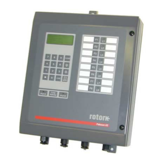
Record the information about your system on data sheets such as those outlined in Section 11. Section 12 has technical information you might need Software level This technical manual relates to Pakscan IIS master stations with software version 5222-020 V1.2 or later. - Page 6 Pakscan IIS Technical Manual Publication S130E Issue 1.0 Fig. 1 - Pakscan IIS Master Station and IQ actuator...
-
Page 7: Introduction
The Pakscan IIS system is compatible with all Pakscan II and IIE field units and setting tools. It also includes the ability to be programmed to operate plant sequences and to interlock the plant output commands. The information relating to the construction and downloading of these programmable functions is contained in the SCT programming manual. - Page 8 Pakscan IIS Technical Manual Publication S130E Issue 1.0 This page is intentionally left blank...
-
Page 9: Equipment Description
EQUIPMENT DESCRIPTION The Pakscan IIS master station is a stand alone unit suitable for mounting on a flat vertical surface. The enclosure is sealed and weatherproof and all access is from the front of the unit. The door, hinged on the left, provides access to the terminals and circuit board inside. - Page 10 When these covers are in place the power, input and output terminals remain accessible. The Pakscan IIS is suitable for an a.c. power supply and there is a single fuse fitted internally. The a.c. power is wired to three terminals (LNE) on the main circuit board.
- Page 11 The remaining terminals are used for the 2 wire loop connections and other system functions. There are no facilities for including any additional option cards within the Pakscan IIS enclosure. The Pakscan IIS master station does not support dual redundant station configurations.
- Page 12 Pakscan IIS Technical Manual Publication S130E Issue 1.0 This page is intentionally left blank...
-
Page 13: Storage Procedure
Pakscan IIS Technical Manual Issue 1.0 Publication S130E STORAGE PROCEDURE On receipt the hardware should be examined for signs of damage and to ensure that the expected equipment is present. If the unit is to be stored for a period of time then normal conditions for keeping electronic hardware must be provided. - Page 14 Pakscan IIS Technical Manual Publication S130E Issue 1.0 Fig. 5 - Outline of Pakscan System Power (ac) Serial Port 1 Serial Port 2 Port A Port B OUT = Term'l 17 IN = Term'l 20 IN = Term'l 18 OUT = Term'l 21...
-
Page 15: Overview Of Pakscan
The Pakscan system is a data monitoring and control system which comprises a master station, in this case a Pakscan IIS, servicing a current loop which can have up to 32 field units connected to it. The current loop may be up to 20 kilometres long. Figure 5 shows an outline of the system. - Page 16 Pakscan IIS Technical Manual Publication S130E Issue 1.0 LOOP A LOOP B RV182 RV181 1 0 2 2 - 5 6 5 IS S U E 1 .1 SK10 SK11 SK12 SK13 Fig. 6- Pakscan IIS main circuit board...
-
Page 17: Initial Setting Up
Pakscan IIS Technical Manual Issue 1.0 Publication S130E INITIAL SETTING UP Before applying any power to the master station you may wish to check that the internal settings of the jumpers match your system requirements. These jumpers will have been factory set to the default positions, or to user specified positions, prior to dispatch. - Page 18 Pakscan IIS Technical Manual Publication S130E Issue 1.0 Jumper / Link . Function Default Action Not used Screen A to earth select link screen ‘A’ to earth Screen B to earth select screen ‘B’ not connected Port 1 mode select...
- Page 19 It is also desirable to bond the screen to a suitable ground to reduce the system susceptibility to noise. This bonding can be achieved either by using the Pakscan IIS ground connection and fitting LK4, or by connecting the screen to a suitable external earth. Even if an external earth connection is used it is still required to connect the screen to the Pakscan IIS terminals in order that the cables from the unit are correctly decoupled.
-
Page 20: External Links (Esd)
In order to simplify the setting up of the RS485 highway to be either 2 or 4 wire and to provide line termination 3 by 4 way DIP switches are provided inside the Pakscan IIS. S1 is used to select 2 or 4 wire operation for both the comms ports and S2 and S3 connect the termination resistors. -
Page 21: Functions
Current Loop Operations Fault Condition - Loopbacks On The Pakscan IIS controls the current loop which communicates with Fig. 9: Loopback system the attached field units. Loop communications divide into two parts; configuration (when the master station decides whether the loop is complete, and if not, where the faults are), and normal operation. -
Page 22: Modbus Serial Interfaces
6.3 Modbus Serial Interfaces The Pakscan IIS master station may be configured with two Modbus serial interfaces, or one Modbus interface and one serial printer interface. In the former case, the two Modbus interfaces perform similarly. The master station's use of the Modbus protocol is described in detail in the protocol documents listed in section 1 (Related Documents). -
Page 23: Installation And Connection
Mounting The Pakscan IIS master station should be mounted on a flat vertical surface and in a suitable environment. The height of the front should be between 1.0 m and 1.7 m above the floor so that the screen may be viewed and the keys accessed. - Page 24 Pakscan IIS Technical Manual Publication S130E Issue 1.0 Fig. 11: System Wiring ACTUATOR TERMINALS...
-
Page 25: Loop Checks
Pakscan IIS Technical Manual Issue 1.0 Publication S130E Port A OUT Cable A Port A IN If there is no signal earth bar - one of the two links LK4 or LK5 should be fitted. Connect the screen to the master station on both Port B IN ends of the cable and fit either LK4 or LK5. - Page 26 Pakscan IIS Technical Manual Publication S130E Issue 1.0 Cable Capacitance The capacitance between the cores, and to the screen, is critical to the system performance. Too high a capacitance for the selected loop baud rate will result in poor communications, or even communication failure.
-
Page 27: Lcd And Keypad
Keypad Security The Pakscan IIS master station can be protected against unauthorised changes by a password, or 'PIN', mechanism. If a PIN has been programmed, it must be entered before particular functions can be accessed. These functions then remain accessible whilst keys are being pressed and for 30 seconds after the last key press. -
Page 28: Menu Structure
Pakscan IIS Technical Manual Publication S130E Issue 1.0 Menu Structure Each page offers the user options to enter commands or move to a different page. These pages and menus are structured as shown below. Top Menu see section 8.3 Master Station... -
Page 29: Master Station Status
Pakscan IIS Technical Manual Issue 1.0 Publication S130E Master Station Status Master tag Master MSTAG001 Status Status=LB OFF Alarms Alarms=P Options 1>M/S 2>FCU 3>More This is the first master station screen which is displayed at power-up The Master Tag is an identity tag which can be configured by the user. - Page 30 Pakscan IIS Technical Manual Publication S130E Issue 1.0 8.3.1 Master Station Commands 1>Reset Loop 9>ESD 4>Diagnostic 5>Setup This screen provides commands and options for the master station itself. Commands available: Command to re-configure loop. This should be used after a loop fault has been corrected.
-
Page 31: Diagnostic Menus
The top line shows the code which indicates the type of the software fitted and its version or issue number as follows; 0210 Pakscan IIS, single 32 channel master station V1.1 software release 1.1 The port activity flags flash to indicate when a message is received (Rx), or when a reply is transmitted (Tx). - Page 32 Pakscan IIS Technical Manual Publication S130E Issue 1.0 8.4.2 Port Diagnostic Displays Port number 1 msg err xcpt 2 msg err xcpt Message counts Mod func addr data Mod func addr data Last message details 1920 1920 These screens give detailed diagnostic information for the serial links. The top half displays counts of various...
- Page 33 Pakscan IIS Technical Manual Issue 1.0 Publication S130E 8.4.3 Loop Diagnostic Display Reason for last loop configuration Loop: Fault found Fault type Loop open circuit Loopback or address of fault details Loopbacks at Loop FCU map 1>FCU map This screen provides information to aid in commissioning and fault-finding on the current loop.
- Page 34 Pakscan IIS Technical Manual Publication S130E Issue 1.0 8.4.4 FCU Map and Failure Counts Physical position Loop position = 10 Address FCU address Attached port Comms fail count Port=A Fails= Field unit type Software version Type=Act S/W= 2.4 The screen displays the order in which field units have been found on the loop during loop configuration.
-
Page 35: Setup Menus
Pakscan IIS Technical Manual Issue 1.0 Publication S130E Setup Menus The Setup options can be password protected. See sections 8.1 and 8.5.8 8.5.1 Top Setup Menu Port 1 setup Port 2 setup 1>Port 1 2>Port 2 Loop setup M/S addresses 3>Loop... - Page 36 Pakscan IIS Technical Manual Publication S130E Issue 1.0 8.5.2 Port Setup Menus Port 1: Port 2: 1>P1 Use =Host 1>P2 Use =Host 2>Generic Modbus 2>Yokogawa Modbus 3>9600 4>Par=Odd 3>19200 4>Par=Even 6> 6> These 2 pages show the current setup for the serial ports.
- Page 37 Pakscan IIS Technical Manual Issue 1.0 Publication S130E 8.5.2.1 Alarm Linkage Port Alarms are Port Alarms are 1>Linked 1>Separate This screen gives the user the option of selecting whether the alarm latches for host ports 1 and 2 are separate or linked.
- Page 38 Pakscan IIS Technical Manual Publication S130E Issue 1.0 8.5.3 Loop Setup Menu Current speed 1>Loop speed = 1200 Highest FCU address 2>Number FCU’s= Loop Doubling enable 3>Doubling This page displays and controls options affecting the current loop. The 'Doubling Enable' allows loop speed doubling to be enabled (ON) or disabled (OFF). If enabled, the master station automatically doubles the loop baud rate if it finds that the loop is complete.
- Page 39 Pakscan IIS Technical Manual Issue 1.0 Publication S130E 8.5.4 Unit Address Setup Menu 1>Masterstation Address for Host Comms 2>Sequence/Interlock Address for Sequence Programmes The master station responds to more than one Modbus unit address on each of its serial communication links.
- Page 40 Pakscan IIS Technical Manual Publication S130E Issue 1.0 8.5.5 Tag Setup Menu Master Station Tag 1>M/S Tag MSTAG001 FCU address 2>FCU FCU’s Tag 3>Tag FCUTAG02 This is the page for editing tag names which may be assigned to the master station and the field units.
- Page 41 Pakscan IIS Technical Manual Issue 1.0 Publication S130E 8.5.6 Date and Time Setup Date 1>Date 05/10/95 Time 2>Time 10:32:00 This page shows the state of the internal real-time clock. It is used within the sequence programming where the sequence requires a time or date action.
- Page 42 Pakscan IIS Technical Manual Publication S130E Issue 1.0 8.5.7 ESD Options Setup Menu ESD Options 1>Serial Disabled 2>Keypad Disabled 3>Input Enabled This page allows the user to select the ESD function. With this screen it is possible to select 1, 2 or all 3 forms of ESD input to either enabled or disabled.
- Page 43 Pakscan IIS Technical Manual Issue 1.0 Publication S130E 8.5.8 Keypad Security Options Keypad Security 1>PIN In use 2>PIN = **** 3>Access Level 3 A security code, PIN, can be set up to prevent unauthorised changes to the master station settings or field unit outputs.
-
Page 44: Field Unit Menus
Pakscan IIS Technical Manual Publication S130E Issue 1.0 8.6 Field Unit Menus The master station displays a screen appropriate to the type of field unit. 8.6.1 Actuator Field Unit Status Display Digital status Tag name OA1 ST0 MO0 FCUTAG01 Digital status... - Page 45 Pakscan IIS Technical Manual Issue 1.0 Publication S130E 8.6.1.1 IQ actuator Second Status Page Current Torque Tag name Torq=85% FCUTAG01 Auxiliary inputs FCU address Aux1=1 Aux2=0 Battery status Aux3=0 Aux4=0 LoBat More options 1>Torque 2> This screen shows the current torque value and the status of the 4 auxiliary digital inputs on an IQ actuator.
- Page 46 Pakscan IIS Technical Manual Publication S130E Issue 1.0 8.6.1.2 IQ Historic Torque Displays Open Torq FCUTAG01 Close Torq FCUTAG01 98<Open 92<Open 1>Close 2>Reload 3> 1>Open 2>Reload 3> These screens show 8 values of torque for the actuator traveling in the opening or closing direction. They are the values which have been most recently received from the field unit.
- Page 47 Pakscan IIS Technical Manual Issue 1.0 Publication S130E 8.6.2 General Purpose Field Unit Status Display Tag name DIN 1-8 FCUTAG01 Digital inputs FCU address 00001111 Measured value 1 Alarms A1=75% Alms=p Measured value 2 Commands page A2=50% 1>Outputs The 8 digital inputs are displayed as 8 '0's and '1's..
- Page 48 Pakscan IIS Technical Manual Publication S130E Issue 1.0 8.6.2.1 Second Page for General Purpose Field Unit Pulse counter Tag name Pulses= 1 FCUTAG01 Relay commands FCU address 1>R1=0 2>R2=0 Battery status 3>R3=0 4>R4=0 Analog output Block & parameter screen 5>A out= 0% 6>...
- Page 49 Pakscan IIS Technical Manual Issue 1.0 Publication S130E 8.6.3 Communications Failure Display Tag name FCUTAG01 FCU address Alarm: Comms Fail Secondary data 5> This display is put up if the field unit is not in communication with the master station.
- Page 50 Pakscan IIS Technical Manual Publication S130E Issue 1.0 8.6.3.1 Field Unit Status Secondary Data FCU address Tag name 1>FCU= FCUTAG01 Block number 2>Block= 5 Data Parameter number Data 3>Para= 0010H Description Motion Inhibit Timer This page allows the user to read any parameter in a field unit. Data in field units is organised into 32 blocks each of 8 parameters, the parameters within each block being related in some way, e.g.
-
Page 51: Sequence And Interlock Menus
Pakscan IIS Technical Manual Issue 1.0 Publication S130E Sequence and Interlock Menus 1>Sequences 2>Data 3>Interlocks This section describes the information displays for sequences and interlocks. To fully understand the data provided detailed knowledge of the programmed sequences and the data structures they are using is required. - Page 52 Pakscan IIS Technical Manual Publication S130E Issue 1.0 8.7.1 Sequence Information Sequence number 1>Sequence Sequence mode 2>Auto Step Sequence phase Step= 134 Phase= 10 Message There are up to 80 sequences in the master station, so the range of sequence numbers permitted is 1 to 80.
- Page 53 Pakscan IIS Technical Manual Issue 1.0 Publication S130E 8.7.2 Sequence Data General Register Register contents 1>Gen.Reg 341= Flag Flag state 2>Flags 126= Database Register Register number 3>Database Reg Register contents Some data items can be examined with this screen. The values of general registers, sequence flags and Modbus database registers from the sequence database are displayed.
- Page 54 PI 23 OAS <> 1 This page provides details of the operation of interlocks within the Pakscan IIS master station. Particular outputs can be interlocked with status bits from other field units, or with items from the sequence data base such as flags.
-
Page 55: Setting Parameters And Downloading Programmes
Pakscan IIS Technical Manual Issue 1.0 Publication S130E SETTING PARAMETERS and DOWNLOADING PROGRAMMES IMPORTANT SAFETY PRECAUTIONS If you are unable to secure the connected equipment into a safe state then disconnecting the loop cable from both ports of the master station will prevent plant operation. -
Page 56: Communication Ports
Pakscan IIS Technical Manual Publication S130E Issue 1.0 Communication Ports The master station is able to be configured for different functions on each of its two communication ports. However the Modbus address of the master station relates to both ports, they cannot differ, in addition the master station has a sequence address as well as a host comms address and these two must never be the same. -
Page 57: Loop Data
Pakscan IIS Technical Manual Issue 1.0 Publication S130E Loop Data In Section 7.4 the various pieces of information relating to the loop wiring and the cable parameters were measured and recorded. When it comes to setting the Master Station Loop Data the Loop Speed has to be compatible with that data (also the individual field units must be set to match the Master Station setting). -
Page 58: Tag Names
Pakscan IIS Technical Manual Publication S130E Issue 1.0 Tag Names It is possible to insert a tag name for every field unit, and also for the master station itself. Tag numbers help maintenance in checking that they have the right MOV. -
Page 59: Final Checks
Pakscan IIS Technical Manual Issue 1.0 Publication S130E The screen revealed will be as shown in section 8.5.8. It is possible to enable or disable the requirement for a PIN or change the Access level from this screen as well as define a new PIN. - Page 60 Pakscan IIS Technical Manual Publication S130E Issue 1.0 This page is intentionally left blank...
-
Page 61: Commissioning The System
Pakscan IIS Technical Manual Issue 1.0 Publication S130E COMMISSIONING THE SYSTEM IMPORTANT SAFETY PRECAUTIONS In order to fully commission the Pakscan Loop it is necessary to ensure that all the system's valves are allowed to be opened and closed. Also any ancillary devices such as pumps and stirrers must be allowed to operate. -
Page 62: Checking The Loop Itself
Pakscan IIS Technical Manual Publication S130E Issue 1.0 10.2 Checking the Loop Itself The most common problem in commissioning is that the field wiring is incorrectly made. If the cable is not connected correctly between the Output side of one field unit and the Input side of the next then the loop will fail to operate. -
Page 63: Checking System Performance
Pakscan IIS Technical Manual Issue 1.0 Publication S130E As the master station progresses through the configuration of the loop it moves through a number of steps: 1. It waits for all field units to revert to loopback on. - Waiting for Loopbacks 1 2. - Page 64 Pakscan IIS Technical Manual Publication S130E Issue 1.0 Method 1 Turn both potentiometers fully anti-clockwise. This sets the voltage to the maximum. To set Port A's voltage. Disconnect the two wires from Port B and re-configure the loop. With the loop running, turn Port A's potentiometer RV181 clockwise until the A LED on the door just goes out.
-
Page 65: Diagnostic Information
Pakscan IIS Technical Manual Issue 1.0 Publication S130E 10.4 Diagnostic Information The master station can provide information via its own display which can help in commissioning and fault finding. 10.4.1 Loop Configuration The loop should configure with no loopbacks. If loopbacks are in use (as indicated by the master station status display), the loop diagnostic screen will indicate which field units have loopbacks asserted. -
Page 66: Final Checks
Pakscan IIS Technical Manual Publication S130E Issue 1.0 In most systems communication errors will occur due to interference from associated plant. The main thing is that they should be relatively infrequent. The system performance can be monitored by examining the counter, waiting a short while, and rechecking the value. -
Page 67: Commissioning Aids
Pakscan IIS Technical Manual Issue 1.0 Publication S130E 10.6 Commissioning Aids Two handheld devices are available to aid commissioning and fault finding. The first is the Paktester, (Field Test Unit), which may be used to interrogate and control a single field unit via the 2-wire interface. - Page 68 Pakscan IIS Technical Manual Publication S130E Issue 1.0 This page is intentionally left blank...
-
Page 69: Set Up Data Records
Pakscan IIS Technical Manual Issue 1.0 Publication S130E SET UP DATA RECORDS The following is a table which should be completed for every master station in your system. Keep the record safe so that in the unlikely event of a failure you can quickly restore the settings when replacing the unit. - Page 70 Pakscan IIS Technical Manual Publication S130E Issue 1.0 Loop Map Complete the following chart showing the position and address and type of each field unit Position Address Type Position Address Type For each field unit you should record the settings made for the performance of the field unit.
- Page 71 Pakscan IIS Technical Manual Issue 1.0 Publication S130E Actuator Field Units (Integral) Actuator Type ........Tag ............FCU Type ....Address ....Baud Rate ....Analogue Update Time ....Analogue Deviation Threshold ....Motion Inhibit Time ....Motion Inhibit Deadband ....
- Page 72 Pakscan IIS Technical Manual Publication S130E Issue 1.0 This page is intentionally left blank...
-
Page 73: Technical Specifications
2A, 130V, 60W, 125VA (exclusive maxima) Output Relays (For data on field units fitted inside Rotork actuators refer to the actuator or field unit data sheets. The integral field units operate in the same environment as the actuator, using the actuator power supply and communicating commands and data directly with the actuator electronics.) -
Page 74: External Connections
Pakscan IIS Technical Manual Publication S130E Issue 1.0 Fig. 15 shows the relationship between cable cross Baud Cable Size sectional area, baud rate and length of loop. e.g. using Rate 0.5 mm² 1.0 mm² 1.5 mm² 1.0 mm² cable and a loop length of between 2.6 km and 5.0 km the loop speed will have to be set to 600 baud. - Page 75 RS232 RS485 CTSA CTSA Terminals 23 to 28 RTSA RTSA COMA These are not used in the Pakscan IIS system. 2 / 4 WIRE TXB + RS232 RS485 Terminals 29 to 31 PORT 2 TXB - (TO HOST)
-
Page 76: Master Station Dimensions
Pakscan IIS Technical Manual Publication S130E Issue 1.0 12.5 Master Station Dimensions Master Station Weight: 5.5 Kg Material: Steel cabinet Weatherproof Rating: IP65 cable access 4 x 20 mm fixing holes 7 mm Pakscan IIS hinge on left side all dimensions in mm... - Page 77 Pakscan IIS Technical Manual Issue 1.0 Publication S130E 12.6 Pushbutton and LED Label Inserts Print within The Function buttons F1 to F8 and LED 1 to 8 can be marks individually labeled by inserting a simple paper label behind the front panel membrane. The labels are inserted in the slots inside the front door.
- Page 78 Rx A - 9 way D type Pin 5 —————————— Switches S1a, S1b, and S2 to be set OFF (Open) RS422/RS485 Link to Rotork PS410 RS485 converter, 4 wire PS410 Converter Master Station 9 way D type Pin 8 ——————————...
-
Page 79: Sequencer Information
Publication S130E 12.8 Sequencer Information The Pakscan IIS master station includes a powerful sequence control function that permits the user to produce sequences for the automatic operation of the plant equipment. In addition every output can include an interlock function to prevent plant mis-operation. -
Page 80: Maintenance
Publication S130E Issue 1.0 12.9 Maintenance The Pakscan IIS master station is not suitable for field repair. Should the unit require maintenance contact your local Rotork representative. Battery Replacement The master station contains a long life battery that should last for at least 3 years when no power is applied and considerably longer in normal use. -
Page 81: Appendix 1 General Safety Information
If such excess is applied, the product should be returned to Rotork or otherwise checked by a competent person before re-use, even if no damage is immediately evident. Use only the specified fuse type and rating as replacements. - Page 82 A single shield may be shared by any number of analogue signal cables. Functional Reliability Reliability predictions, (including failure mode and effect analysis), are calculated by Rotork using statistical methods and the resulting figures should only be used for statistical purposes. These predictions are only valid if the maintenance procedures and maintenance intervals stated in Rotork documentation are observed.
- Page 83 Pakscan IIS Technical Manual Issue 1.0 Publication S130E This page is intentionally left blank...
- Page 84 Pakscan IIS Technical Manual Publication S130E Issue 1.0 UK head office USA head office Rotork Controls Ltd Rotork Controls Inc Bath, England 19 Jet View Drive telephone Bath (01225) 733200 Rochester telefax (01225) 333467 New York 14624, USA telephone Rochester (716) 328 1550...
Need help?
Do you have a question about the Pakscan IIS and is the answer not in the manual?
Questions and answers