Garmin SL30 Pilot's Manual
Nav/comm transceiver
Hide thumbs
Also See for SL30:
- Installation manual (88 pages) ,
- Pilot's manual (56 pages) ,
- Quick reference manual (2 pages)
Table of Contents
Advertisement
Quick Links
Download this manual
See also:
Installation Manual
Advertisement
Table of Contents

Related Manuals for Garmin SL30


Summary of Contents for Garmin SL30
- Page 1 SL30 nav com pilot’s guide...
- Page 2 Information in this document is subject to change without notice. Garmin reserves the right to change or improve its products and to make changes in the content with- out obligation to notify any person or organization of such changes or improvements. Visit the Garmin Web site (www.garmin.com) for current updates and supplemental information concerning the use and operation of this and other Garmin products.
-
Page 3: Welcome
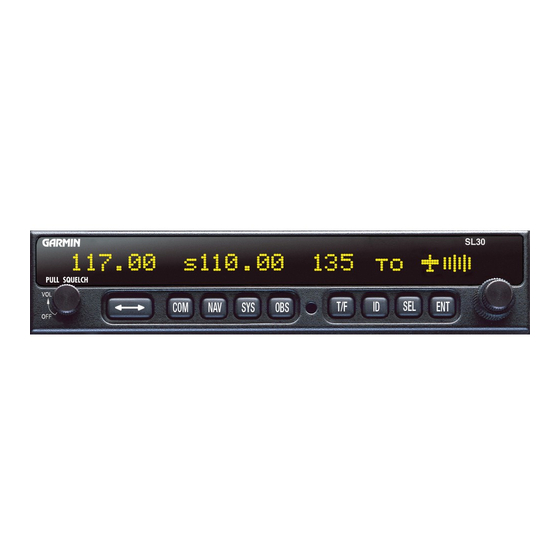
Welcome ... Welcome to a new era of aviation communication and navigation. Once again, Garmin AT, Inc. has set new standards in features and ease of use for the general aviation public. The SL30 is a VHF Navigation/Communications Transceiver for use by the aviation pilot. The SL30 is packaged in a slim form factor that helps you get the most out of limited panel real estate without limiting features and performance. -
Page 4: Ordering Information
Introduction Ordering Information To receive additional copies of the SL30 User’ s Guide, order part #560-0403-xx. The SL30 Installation Guide is part #560-0404-xx. The Quick Reference Guide is part #561-0262-xx. About This Manual Please take a few moments to review the various sections in this manual. Even if you are an experienced user of Nav/Coms, be sure to read our Getting Started section. -
Page 5: Table Of Contents
Nav Options ... 30 Nav Audio Level ... 30 Nav/Com Mixing Level ... 30 Additional CDI Info ... 30 Display Ident over OBS ... 30 Com Options ... 31 RF Signal Level ... 31 Com Noise Level ... 31 Mic 1 and 2 Squelch ... 31... - Page 6 Introduction Transmit Mic ... 31 Intercom Level ... 32 Sidetone Level ... 32 Headphone Level ... 32 VOR Equipment Test ... 32 Appendix ... 33 Troubleshooting ... 33 Installation Configurations... 36 Specifications ... 37 General Features ... 37 Com Radio Features ... 38 Physical Specifications ...
-
Page 7: Getting Started
Getting Started Combining a powerful 760 channel VHF communications transceiver with 200 channel VOR, Localizer and Glideslope receivers, the SL30 provides a full-functioned navigation and communications solution in a small footprint at a very affordable price. Besides tradi- tional Nav/Com features, the SL30 also incorporates workload-reducing functions such as automatic decoding of the Morse code station identifier for VOR/LOC, most-used frequency storage in memory, built-in course deviation indicator, and more. -
Page 8: Display
Getting Started Display The SL30 Nav/Com uses a single line by 32-character 5x7 dot matrix alphanumeric dis- play. A photocell is located in the top left corner of the front panel display. The photocell automatically controls the light intensity of the display LEDs from low brightness at night to high brightness during daylight operation. -
Page 9: Flip/Flop
Flip/Flop Press the FLIP/FLOP button to switch between the active (left-most) and standby (right- most) frequency. Switching between Com frequencies is disabled while you are transmit- ting. Press COM to select the Com radio mode. The annunciator will light above the button when you are in Com mode. -
Page 10: T/F
Getting Started Press T/F to toggle between the bearing TO or radial FROM the active VOR. The T/F but- ton does not operate for Localizer frequencies. Press ID to select the Nav audio and toggle between VOICE or IDENT. Pressing ID will cancel the VOR monitor function. -
Page 11: Operation Summary
Operation Summary Power On Turn the SL30 on. Either turn the Power/Volume knob clockwise to turn the power on or, if installed, turn on the master switch that powers the radios. The SL30 will go through a short initialization routine and then briefly display the last VOR check date. -
Page 12: Selecting A Com Frequency
Getting Started Selecting a Com Frequency New frequencies are first selected as a Standby frequency and then toggled to the Ac- tive side when desired. While viewing the Standby frequency display, use the LARGE and SMALL knobs on the right side of the SL30 to select the desired frequency. 1. -
Page 13: System Mode
System Mode In the System mode you can view software versions, setup the Nav and Com functions, and record VOR test information. See the Advanced Operations section for more details. OBS Mode Press the OBS button. If the annunciator above the button lights, then you may use the LARGE and SMALL knobs to adjust the Omni Bearing Selector. -
Page 14: Emergency Channel
Getting Started Emergency Channel The standard emergency channel (121.50 MHz) is stored in the Com memory of the SL30. 1. Press COM, if you aren’t in Com mode already. Press SEL. Turn the LARGE knob to the Emergency channel, one position counter-clockwise will reach it fastest. 119.10 s124.55 emrgncy 121.50 2. -
Page 15: Advanced Operation
Advanced Operation Com Radio Mode Monitoring the Standby Com Channel The Frequency Monitoring function allows you to monitor the Standby frequency for activity, while listening to the Active frequency. Press the COM key in the Com function to listen to the standby frequency. A small “m” will replace the “s”... -
Page 16: Removing A Com Channel
Advanced Operation Com Mode Remote Flight Service Station (RFS), Unicom (UNI), and Mandatory Frequency (MF). 1. While in Com mode, press ENT. The right side of the display will show “store as” with a flashing cursor at the first character of the name. 119.10 s124.55 2. -
Page 17: Recalling Com Channels
3. Press ENT. The right side of the display will show “store as” with a flashing cursor at the first character of the name. 4. Use the LARGE and SMALL knobs to enter the previously used name and frequency type. 5. -
Page 18: Remote Com Channel Lists
Advanced Operation Com Mode Remote Com Channel Lists Database information can be read when your SL30 is connected to another device, such as the SL60. Each remote list begins with a facility identifier, such as PDX, SLE, LAX, etc. The LARGE knob scrolls through the remote, and other, lists. The SMALL knob scrolls through the channels in each list. -
Page 19: Weather Channels
Weather Channels The standard weather channels are stored in the memory of the SL30. You cannot transmit on a weather channel frequency. Weather channels are not available in all locations. Weather Frequencies 162.400 MHz 162.425 MHz 162.450 MHz 162.475 MHz 162.500 MHz 162.525 MHz 162.550 MHz... -
Page 20: Stuck Mic
Advanced Operation Com Mode Stuck Mic The SL30 helps protect you from a situation where the microphone may get stuck in the ON or Transmit position. If the microphone is keyed for longer than 35 seconds, the SL30 will return to the receive mode on the selected frequency. A “Stuck Mic”... -
Page 21: Nav Radio Mode
Nav Radio Mode Monitoring the Standby Nav channel The Nav radio provides a monitor function for VORs as the standby channel similar to the Com radio. The monitor function is activated or deactivated by pressing the NAV button while in the Nav function. The From radial for the standby channel is shown in parentheses when the VOR monitor mode is activated. -
Page 22: Navigating Along A Back Course Approach
Advanced Operation Nav Mode Navigating along a Back Course approach 1. Press NAV to select the Nav receiver. 2. Set the Localizer frequency of your approach as the Active channel. 3. Press SEL. The display will prompt you to enable the back course. Press ENT to enable the back course. Press SEL and ENT again to disable the back course when it’s appropriate. -
Page 23: Navigating To A Mahp
Navigating to a MAHP 1. Press NAV to select the Nav receiver. 2. Set the VOR frequency for the radial you are following to the MAHP as the Active channel. 3. Set the Standby channel to the appropriate VOR and note where a radial crosses the MAHP for your runway. -
Page 24: Listening To The Audio Channel
Advanced Operation Nav Mode Listening to the Audio channel The audio for the active Nav channel is toggled between modes using the ID button. The annunciator above the button will light while Nav audio is activated, and the detected audio signal will be sent to the Nav audio output circuit. -
Page 25: Saving A Nav Channel
Saving a Nav channel You can save the frequency in the Standby position and give it a name of up to four char- acters. Additional information can be saved along with the name, if the selection is a Localizer or ILS. ILS selections may include the runway number (01-36) and designation (L, R, or C). Up to 250 Com and Nav frequencies may be saved. -
Page 26: Recalling A Nav Channel
Advanced Operation Nav Mode Recalling a Nav channel There are several lists of channels that you can recall from memory in Nav mode. Remote Localizer, remote VORs, the ten most recently used channels in Nav mode, and the user- stored channels. 1. -
Page 27: Remote Localizer List
Remote Localizer List If Localizer channels have been sent by an external device, then this list will be the first displayed for convenience while preparing for a landing. The list shows the airport identifier on the left, a runway identifier for the station in the center, and the channel frequency on the right. -
Page 28: Dst Data Display
Advanced Operation Nav Mode DST Data Display When the SL30 has received data from an external device, such as a DME sensor, through the serial port, DST data is added to the Nav recall list. If you aren’t connected to an external sensor, you will not see this display. -
Page 29: Obs Mode
2. Press ENT to disable the display of DST data. The DST data display may be deactivated by pressing either T/F or OBS in addition to the “Remove DST Data?” screen. OBS Mode OBS Operation OBS mode enables the VOR CDI which is displayed on the right side. The OBS course setting is shown in the center of the display. - Page 30 Advanced Operation Nav Mode identifier will replace the OBS value when it receives the identifier message. 111.80 s117.40 111.80 s117.40 The CDI display is selected by pressing the OBS button. The CDI display is not available if the SL30 is set to use an external indicator head that does not provide a resolver input. The graphic CDI shows an airplane icon at the center that points up in the To condition or down for From.
-
Page 31: Localizer
except in Back Course mode. When you see only the airplane icon you are on course. Additional information may be displayed on the clear side of the CDI. This optional information is selected in a system menu and includes a to or from indicator, a numeric representation of the deflection in tenths of degrees, or nothing at all. -
Page 32: To/From Radial
Advanced Operation Nav Mode flagged and the needle will be centered. This will make the Back Course approach easier since false or misleading glideslope information is not displayed. SL30 1) Press NAV and then set the appropriate Localizer channel into the Active position. 2) Enable the Back Course. - Page 33 Advanced Operation Nav Mode 112.80 s117.40 from 115 The T/F button selects the To or From radial display. If the VOR radial display is not currently shown, press T/F to show the radial display. When the VOR radial is displayed, pressing T/F will toggle between the Bearing To and Radial From the VOR.
-
Page 34: System Mode
Advanced Operation System Mode System Mode Configuration adjustments for the SL30 are made in the System mode. When you press the SYS but- ton, the annunciator above the button will light, and the display will change to the System mode menus. The menus available are: •... -
Page 35: System Info
System Info System Info provides information about the Software versions and the Display Intensity. 1. Press and turn the LARGE knob if necessary to the System Info page. Press ENT. 2. Turn the LARGE knob to view the selections. Software Version The Software version is available for reference when you contact Technical Support. -
Page 36: Nav Options
Advanced Operation System Mode Nav Options Nav Audio Level This setting is for the SL30’ s output to its external audio panel. The factory default value is “Variable”, which slaves it to the volume knob. The range of values it can be set to are 1 to 100. -
Page 37: Com Options
Com Options The Com Options selection allows you to set up options available for Com radio opera- tion. 1. In the System mode rotate the LARGE knob to display the Com Options page. Press ENT. 2. Rotate the LARGE knob to view the Com Options RF Signal Level The RF Level function shows the relative signal strength of the active frequency. -
Page 38: Intercom Level
Advanced Operation System Mode Intercom Level This function adjusts the Intercom Audio Level. Turn the SMALL knob to change the value. The range is from 1 to 100. Setting the value to “variable” slaves the intercom level to the volume control knob. Sidetone Level This function displays and adjusts the sidetone audio level that is heard when the trans- mitter is keyed. -
Page 39: Appendix
Troubleshooting If efforts to resolve the problem fail, contact your dealer or the factory for technical as- sistance. The Garmin customer service staff will gladly assist you. Please have the following information ready: • System configuration (products, antennas, mounting locations, etc.) •... - Page 40 Appendix Problem Possible Cause SL30 does not power on No power to the SL30 Faulty electrical wiring or connection No Nav audio Output disabled or set to a low level Nav audio in Com Mixed with Com feature SL30 does not transmit Weather channel is selected No power to Com Mic key connection...
- Page 41 Problem Possible Cause Intercom doesn’t function Input not connected No voice activation, or must talk too loud Can’t change active frequency Com Radio not communicat- OBS readout displays “---” Resolver failure Calibration error Display shows Corrupted system calibration “Incorrect Calibration Check- parameters sum”...
-
Page 42: Installation Configurations
Appendix Installation Configurations Certain functions are either available or not depending on the configuration of your par- ticular installation. The following table illustrates the features available for the described installations. A feature that is available is indicated by the black dot. VOR Monitor VOR CDI Display... -
Page 43: Specifications
Specifications General Features 32 character high-intensity alphanumeric LED display Sunlight readable full alphanumeric display Automatic display intensity Back-lit buttons 200 channel memory (stored alphabetically) Remote frequency flip-flop input pin Navigation Radio Features 200 channel Nav with solid state DSP technology VOR/Localizer and Glideslope receivers Built-in VOR/Localizer converter Frequency range:... -
Page 44: Com Radio Features
Appendix LOC enable annunciator output Internal RF diplexor Active and standby flip/flop frequencies DME or other DST (Distance, Speed, Time) tuning an data display Com Radio Features 760 communications channels Frequency range 118 to 136.975 MHz Active and standby flip/flop frequencies Volume control Tunes to National Weather Service broadcasts Transmit status indicator... -
Page 45: Nav Radio Performance Specifications
Appendix NAV Radio Performance Specifications Input voltage range 10 to 40 VDC Operating temperature range –20ºC to +55ºC Certified TSO C34e/JTSO C34e (Glideslope receive) Certified TSO C36e/JTSO C36e (ILS Localizer receive) Certified TSO C40c/JTSO 2C40c (VOR receive) Certified TSO C66c/JTSO 2C66b (DME display) Com Radio Performance Specifications Input voltage range 10 to 40 VDC Operating temperature range –20ºC to +55ºC... -
Page 46: System Interfaces
Appendix System Interfaces Navigation Receiver The SL30 can be installed in several configurations based upon individual requirements. This includes with or without an external course deviation indicator. The CDI may be discrete, serial, or composite. Com Transceiver For standalone installations, the Com requires connections to: •... -
Page 47: Localizer And Paired Glideslope Frequencies
Localizer and Paired Glideslope Frequencies Localizer MHz Glideslope MHz 108.10 334.70 108.15 334.55 108.30 334.10 108.35 333.95 108.50 329.90 108.55 329.75 108.70 330.50 108.75 330.35 108.90 329.30 108.95 329.15 109.10 331.40 109.15 331.25 109.30 332.00 109.35 331.85 109.50 332.60 109.55 332.45... - Page 48 Appendix Localizer MHz Glideslope MHz 109.75 333.05 109.90 333.80 109.95 333.65 Each displayed localizer frequency is paired with a glideslope frequency that is not dis- played. Localizer MHz Glideslope MHz 111.75 333.35 111.90 331.10 111.95 330.95...
-
Page 49: Vor Station Frequencies
VOR Station Frequencies VOR stations occur every 50 kHz from 112.00 through 117.95 MHz and on the following frequencies in the 108 to 112 MHz band. 108.20 109.20 108.25 109.25 108.40 109.40 108.45 109.45 108.60 109.60 108.65 109.65 108.80 109.80 108.85 109.85 109.00... -
Page 50: Compliance, License, And Warranty Information
Consult the dealer or an experienced radio/TV technician for help. The SL30 does not contain any user-serviceable parts. Repairs should only be made by an authorized Garmin service center. Unauthorized repairs or modifications could result in permanent damage to the equipment,... -
Page 51: Software License Agreement
ING SOFTWARE LICENSE AGREEMENT. PLEASE READ THIS AGREEMENT CAREFULLY. Garmin grants you a limited license to use the software embedded in this device (the “Software”) in binary ex- ecutable form in the normal operation of the product. Title, ownership rights, and intellectual property rights in and to the Software remain in Garmin. -
Page 52: Limited Warranty
Garmin retains the exclusive right to repair or replace the unit or software or offer a full refund of the purchase price at its sole discretion. SUCH REMEDY SHALL BE YOUR SOLE AND EXCLUSIVE REMEDY FOR ANY BREACH OF WARRANTY. - Page 53 Getting started 1 Monitor;Standby Nav channel 15 Glideslope;Frequencies 41 Morse code i, 1, 18, 23, 25, 26, Headphone 32 HSI 26 Nav/Com audio mixing 30 Nav;Audio level 30 Nav;Autolist channels 21 Nav;Button 3 Ident (ID);Button 4 Nav;Mode 15 ID mode 18 Nav;Monitor standby 15...
- Page 54 Index Standby;Nav 15 Stuck mic 14 Power 2 Support 45 Product Support 45 System 28 System (SYS);Button 3 Recall;Com channels 11 Recalling frequencies 7 Time data 22 Registration 45 To/From;Button 3 Remote;Com channels 12 To/From;Radial 26 Remote;VOR list 21 Troubleshooting 33 Remove Com channel 10 RF signal level 31 User channels 12, 21...
- Page 56 Street, Olathe, Kansas 66062, U.S.A. Garmin (Europe) Ltd. Unit 5, The Quadrangle, Abbey Park Industrial Estate, Romsey, SO51 9DL, U.K. Garmin Corporation No. 68, Jangshu 2 Road, Shijr, Taipei County, Taiwan www.garmin.com Part Number 560-0403-01 Rev. C (Garmin P/N 190-00486-00)
Need help?
Do you have a question about the SL30 and is the answer not in the manual?
Questions and answers