Garmin Apollo SL30 COMM Installation Manual
Nav/comm transceiver
Hide thumbs
Also See for Apollo SL30 COMM:
- User manual (48 pages) ,
- Quick reference manual (2 pages) ,
- Installation (2 pages)
Table of Contents
Advertisement
Quick Links
Advertisement
Table of Contents

Related Manuals for Garmin Apollo SL30 COMM


Summary of Contents for Garmin Apollo SL30 COMM
-
Page 1: Installation Manual
Apollo Model SL30 NAV/COMM Installation Manual August 2003 560-0404-03a... - Page 2 No part of this document may be transmitted, reproduced, or copied in any form or by any means without the prior written consent of Garmin AT, Inc. Due to Garmin AT’s commitment to constantly improve the quality and performance of our products, information contained in this document is subject to change without notice.
-
Page 3: History Of Revisions
ISTORY OF EVISIONS Revision Date 11/16/99 2/10/00 8/2/01 2/21/02 8/26/03 MPORTANT “The conditions and tests required for TSO approval of this article are minimum performance standards. It is the responsibility of those desiring to install this article on or within a specific type or class of aircraft to determine that the aircraft operating conditions are within TSO standards. - Page 4 OTES...
-
Page 5: Table Of Contents
ABLE OF ONTENTS SECTION 1 - INTRODUCTION ... 1 ... 1 BOUT ANUAL SL30 D ... 1 POLLO ESCRIPTION ... 2 EATURES ...2 ENERAL EATURES ...2 AVIGATION ADIO EATURES ...3 ADIO EATURES ...3 HYSICAL PECIFICATIONS NAV R ADIO ERFORMANCE PECIFICATIONS ADIO ERFORMANCE PECIFICATIONS... - Page 6 Table of Contents ... 33 ETUP AND HECKOUT ... 37 INAL YSTEM HECK NSTRUCTIONS FOR ONTINUED SECTION 3 - SPECIFICATIONS ...41 ...41 LECTRICAL ...41 HYSICAL ...41 NVIRONMENTAL ...42 VIONICS UTPUTS NAV R ECEIVER ERFORMANCE VOR ... 43 ... 43 OCALIZER ...
- Page 7 ... 61 ESSAGE EFINITIONS ...61 NPUT ESSAGES VOR L ...62 EMOTE ...64 EMOTE OCALIZER ...66 EQUEST UTPUT VOR/LOC F CTIVE REQUENCY AND VOR/LOC F TANDBY REQUENCY AND COMM F TANDBY REQUENCY AND COMM F CTIVE REQUENCY AND NAV A ...69 UDIO (OBS) V EARING...
- Page 8 Table of Contents IST OF ABLES 1 - P ABLE ACKAGE ONTENTS 2 - C ABLE NTERFACE 3 - R ABLE ANEL ONNECTOR 4 - T ABLE ROUBLESHOOTING 5 - D ABLE UTPUT EQUESTS IST OF LLUSTRATIONS 1 - SL30 F IGURE RONT ANEL...
-
Page 9: Section 1 - Introduction
1 - I ECTION NTRODUCTION BOUT ANUAL This manual describes the installation of the Apollo SL30 Nav/Comm units. It is intended for use by persons certified by the Federal Aviation Administration (FAA) to install aircraft navigation devices. It includes installation and checkout procedures for the SL30 unit to standards described in FAA advisory circulars AC 20-67B (for Comm). -
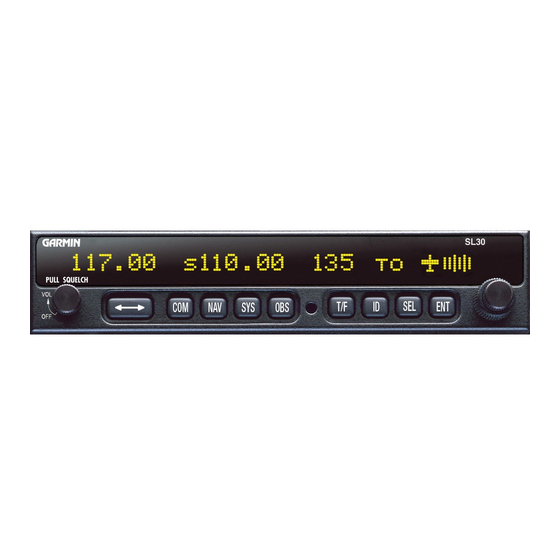
Page 10: Anel
Introduction Figure 1 - SL30 Front Panel EATURES ENERAL EATURES • 32 character high-intensity alphanumeric LED display • Sunlight readable full alphanumeric display • Automatic display intensity • Back-lit buttons • 200 channel memory (stored alphabetically) • Remote frequency flip-flop input pin AVIGATION ADIO EATURES... -
Page 11: Comm Radio Features
• Internal RF diplexor • Active and standby flip/flop frequencies • DME tuning and data display ADIO EATURES • 760 communications channels • Frequency range 118 to 136.975 MHz • Active and standby flip/flop frequencies • Volume control • Tunes to National Weather Service broadcasts •... -
Page 12: System Interfaces
Introduction YSTEM NTERFACES AVIGATION ECEIVER The SL30 can be installed in several configurations based upon individual requirements. This includes with or without an external course deviation indicator. The CDI may be discrete, serial, or composite. RANSCEIVER For standalone installations, the Comm requires connections to: •... -
Page 13: Unpacking The Equipment
ACKAGE ONTENTS As shipped from the Garmin AT factory, the Apollo SL30 package includes most items necessary for installation other than supplies normally available at the installation shop, such as wire and cable ties, and required input and output equipment. The standard items included in the package are listed in Table 1. -
Page 14: Ther Required Aterials
Introduction THER EQUIRED ATERIALS The SL30 is intended for use with standard aviation accessories. External devices required for various installations are listed below. Depending upon the installation, this will include items such as: • back course annunciator • a CDI or HSI •... -
Page 15: License Requirements
ICENSE EQUIREMENTS An aircraft radio station license may be required for operation of the SL30 Comm transmitter once installed in the aircraft. An application must be submitted on FCC Form 404, Form 605 or later revised application, which may be obtained from the FCC in Washington, DC, or any of its field offices. - Page 16 Introduction OTES Apollo SL30 Installation Manual...
-
Page 17: Section 2 - Installation
2 - I ECTION NSTALLATION This section describes the installation of the SL30 including mounting, wiring, and connections. A post installation check-out procedure is included at the end of this section. NSTALLATION NFORMATION Always follow good avionics installation practices per FAA Advisory Circulars (AC) 43.13- 1B, 43.13-2A, and AC 20-67B, or later FAA approved revisions of these documents. -
Page 18: Equipment Mounting
Installation 3. The valid flag sensitivity shall be 125 mV ± 10% for the flag to leave the stop and 260 mV ± 10% maximum for flag to be fully concealed. 4. The To/From flag shall have an input impedance of 200 ohms ± 10% and a sensitivity of ±... -
Page 19: Pacing
dimples help maintain the proper clearance. The mounting tube must be installed with the clearance dimples pointing up. The mounting tube should be flush to the instrument panel and allow sufficient clearance for the back of the bezel of the unit to mount flush to the mounting tube. Sufficient clearance must exist in the instrument panel opening to allow ease of insertion and removal of the unit. -
Page 20: Unit Insertion
Installation NSERTION Position the cam lock as shown below. The front lobe of the cam should be vertical. The cam lock mechanism should be fully unscrewed (turned counter-clockwise). Slide the unit into the frame. Turn (clockwise) and carefully hand-tighten (4 in-lb max.) the cam lock mechanism using only the 3/32"... - Page 21 Installation Figure 4 - Mounting Frame Assembly Figure 5 - Cable Routing Apollo SL30 Installation Manual...
-
Page 22: Electrical Connections
Installation LECTRICAL ONNECTIONS The SL30 installation kit includes 15- and 37-pin d-sub shells and crimp contacts. The crimp contacts are specified for 20 to 24 awg wire. Make the crimp connections with a crimp tool as specified on page 6. All wires should be 20 to 24 AWG unless otherwise specified. Wiring diagrams are included in this section. -
Page 23: Microphone Inputs
ICROPHONE NPUTS Microphone input connections should be made using a twisted pair shielded cable. Attach the signal ground to the mic ground pin on the rear connector and connect the shield to the rear connector plate. RANSMIT NPUT The TxKey input on the rear connector must be pulled low to ground to enable the transmitter. -
Page 24: Use Of Splitter And Combiner
Installation Clamp Nut Step 1. 0.031 Braid Clamp Step 2. Step 3. Solder Center Conductor Assembly instructions for right angle connector part #162-1008 Figure 6 - Rear Coax Connector Assembly SE OF PLITTER AND The SL30 is the smallest, most advanced NAV/Comm unit on the market. Its size dictates room for only one Comm antenna input and one NAV antenna input. -
Page 25: Equipment Interface
GS Antenna Installations should use an appropriate splitter/combiner, such as the Mini-Circuits ZFSC-2- 1B BNC, available as an option under the Garmin AT part number 115-0007. This unit has been fully environmentally qualified for use with single and dual SL30 installations. - Page 26 Installation Figure 7 - SL30 Comm Wiring Diagram Apollo SL30 Installation Manual...
- Page 27 Installation Figure 8 - SL30 Comm Typical Audio Panel Connections Apollo SL30 Installation Manual...
- Page 28 Installation SL30 37-Pin Connector Power + Ground NAV Audio Audio Gnd Antenna 1. Nav Audio may be left floating at the SL30. NOTES: 2. Connect shields to designated ground block at the SL10/15. 3. Avionics power leads should use 20 awg wire. All others are specified at 22-24 awg. 4.
- Page 29 Installation Figure 11 - SL30 - GX50/60 - MX20 Connections Apollo SL30 Installation Manual...
-
Page 30: Md200-306/307
Installation SL30 Rslvr{H} Rslvr{C} Rslvr{D} Rslvr{E} Rslvr{F} Rslvr{G} +NAV Flag -NAV Flag +GS Flag -GS Flag +TO Flag +FR Flag GSI Up GSI Down CDI Left CDI Right Back Crse ILS Enbl 37-Pin Connector * Ground for 14V lighting **Appropriate Aircraft Bus NOTES: 1. -
Page 31: Onnections
SL30 Rslvr{H} Rslvr{C} Rslvr{D} Rslvr{E} Rslvr{F} Rslvr{G} +NAV Flag -NAV Flag +TO Flag +FR Flag CDI Left CDI Right Back Crse ILS Enbl 37-Pin Connector NOTES: 1. Use shieled cable for resolver signals 2. Connect cable shields to the mounting frame: pigtails < 1.25 inches 3. -
Page 32: Ont Md200-306/307
Installation Figure 14 - SL30 NAV and ACU to Mid-Cont MD200-306/307 Apollo SL30 Installation Manual... - Page 33 SL30 Rslvr{H} Rslvr{C} Rslvr{D} Rslvr{E} Rslvr{F} Rslvr{G} +NAV Flag -NAV Flag +GS Flag -GS Flag +TO Flag +FR Flag CDI Left CDI Right GSI Up GSI Down Back Crse ILS Enbl 37-Pin Connector NOTES: 1. Use shieled cable for Resolver signals 2.
-
Page 34: Iring
Installation SL30 Bendix/King KN 72 GSI Up GSI Down +GS Flag -GS Flag ILS Enbl Composite 37-Pin Connector NOTES: 1. Connect shield grounds to aircraft chassis with as short a conductor as practical. 2. Refer to Limitations on Using Composite Signal paragraph in this chapter. 3. -
Page 35: Iring
SL30 Lamp Voltage Back Course From Dimmer Amber Circuit Light GSI Up GSI Down +GS Flag -GS Flag CDI Right CDI Left NAV Flag + NAV Flag - + From + To Rslvr{H} Rslvr{C} Rslvr{D} Rslvr{E} Rslvr{F} Rslvr{G} 37-Pin Connector NOTES: 1. - Page 36 Installation SL30 Rslvr{H} Rslvr{C} Rslvr{D} Rslvr{E} Rslvr{F} Rslvr{G} +NAV Flag -NAV Flag +GS Flag -GS Flag +TO Flag +FR Flag GSI Up GSI Down CDI Left CDI Right Back Crse ILS Enbl 37-Pin Connector NOTES: 1. Use shieled cable for resolver signals. 2.
-
Page 37: C Onnections
SL30 +GS Flag -GS Flag GSI Up GSI Down ILS Enbl Composite 37-Pin Connector NOTES: 1. Use shieled cable for resolver signals. 2. Connect cable shields to the mounting frame: pigtails < 1.25 inches. 3. Connect shields chassis ground at both ends of each shielded cable. 4. - Page 38 Installation SL30 Lamp Voltage Back Course From Dimmer Amber Light GSI Up GSI Down +GS Flag -GS Flag GS Superflag CDI Right CDI Left NAV Flag + NAV Flag - NAV Superflag + From + To Rslvr{H} Rslvr{C} Rslvr{D} Rslvr{E} Rslvr{F} Rslvr{G} 37-Pin Connector...
-
Page 39: Pn-101 W Iring
SL30 Lamp Voltage Back Course From Dimmer Amber Light GSI Up GSI Down +GS Flag -GS Flag GS Superflag CDI Right CDI Left NAV Flag + NAV Flag - NAV Superflag + From + To Rslvr{H} Rslvr{C} Rslvr{D} Rslvr{E} Rslvr{F} Rslvr{G} 37-Pin Connector NOTES:... -
Page 40: Iring
Installation SL30 Lamp Voltage Back Course From Dimmer Amber Circuit Light GSI Up GSI Down +GS Flag -GS Flag CDI Right CDI Left NAV Flag + NAV Flag - + From + To Rslvr{H} Rslvr{C} Rslvr{D} Rslvr{E} Rslvr{F} Rslvr{G} 37-Pin Connector NOTES: 1. -
Page 41: Imitations On Distance Speed And Time Nformation
IMITATIONS ON SING A If an external converter is driven from the composite output in conjunction with a full function CDI/HSI with resolver, the indicator head type, when selected from the Setup Mode during the post installation checkout, should be R output will be disabled whenever the VOR monitor mode is active or back course localizer mode is enabled. - Page 42 : For use with serial Electronic Flight Instruments (EFIS) conforming to ERIAL Garmin AT SL30 serial data specification. See Appendix E – Serial Interface Specifications. If serial OBS data is not received at a minimum 1 Hz rate, the NAV unit will flag.
- Page 43 Control Test In the Setup Mode, turn the large knob to reach the C the operation of the front panel controls on the SL30. 1. Press each button. The function name for each control will appear on the display after the button is pressed.
- Page 44 Installation 3. Rotate the small knob to change the value. The values "0-6" may be used to center the GSI needle. 4. Turn the small knob left or right to center the needle. 5. Press ENT when the needle is centered. 6.
-
Page 45: Final System Check
Enable weather frequencies This function determines whether the weather frequencies in common use in North America are displayed, or not. 1. In the Setup Mode, rotate the large knob to select E 2. Press SEL to activate selection. The Yes or No value will flash. 3. -
Page 46: F Eatures
Installation 4. Verify that the remote frequencies of the airport selected via the GPS unit are displayed on the SL30. The interface to a DST data source (such as an Apollo GX or DB30) should be checked as follows: 1. Operate the SL30 in NAV mode and ensure the DME is operating with a valid signal. 2. - Page 47 SL30 P POLLO NSTALLATION ONFIGURATION NFORMATION SL30 NAV/COMM 430-6040-3_____ Mod ____ Serial # ___________ HECKOUT AND Avionics Outputs: [ ] Resolver [ ] Converter [ ] Calibration (if Resolver) [ ] Control Test [ ] Display Test [ ] NAV Valid flag [ ] TO/FROM flag (OFF, TO, FROM) [ ] External annunciator (BC) [ ] CDI (left, mid, right)
-
Page 48: Instructions For Continued Airworthiness
Installation NSTRUCTIONS FOR Modification of an aircraft for the installation of the SL30 obligates the aircraft operator to include the maintenance information provided by this section in the operator’s Aircraft Maintenance Manual and the operator’s Aircraft Scheduled Maintenance Program. 1. Maintenance manual information (system description, operation, location, removal, testing, etc.) is contained within this document and any information should be copied to, and/or included with, the operator’s airplane Maintenance Manual. -
Page 49: Section 3 - Specifications
3 - S ECTION PECIFICATIONS This section includes detailed electrical, physical, environmental and performance specifications for the Apollo SL30. Note: Performance specifications are measured at ambient temperatures unless otherwise noted. LECTRICAL Input voltage... 10 VDC to 36 VDC, reverse polarity protected Input current (VHF navigation input) ... -
Page 50: Avionics Outputs
Specifications Figure 23 - Unit Dimensions VIONICS UTPUTS CDI L/R deviation ...±150 mV full scale, will drive up to 200-ohm load TO/OFF/FROM flag ...±250 mV, TO/FROM indication, will drive up to Nav valid flag...+300 mV for valid indication, will drive up to 200- Nav superflag ...Vin - 2 volts minimum for valid, source capability GSI U/D deviation ...±150 mV full scale, will drive up to 200-ohm load GS valid flag ...+300 mV for valid indication, will drive up to 200-... -
Page 51: Nav Receiver Performance
NAV R ECEIVER ERFORMANCE TSO/JTSO compliance... TSO-C40c (DO-196)/JTSO 2C40c Applicable documents ... RTCA DO-196 Operational class ... N/A Accuracy category... B {-46 Frequency range ... 108.00 to 117.95 MHz in 50 kHz increments Frequency tolerance ... 0.0008% Cross modulation products... At least 60 dB down Receiver sensitivity ... -
Page 52: Glideslope
Specifications Audio response ...Less than 6 dB variation from 350 Hz to 2500 Hz LIDESLOPE TSO compliance...TSO-C34e (DO-192)/JTSO C34e Applicable documents...RTCA DO-192 Operational class...N/A Accuracy category ...B {-46 Frequency range...329.150 to 335.00 MHz Frequency tolerance ...0.0008% Cross modulation products ...At least 60 dB down Receiver sensitivity...-95 dBm typical Centering error ...RTCA DO-195 two sigma limit: 6.7% of full scale OBS R... -
Page 53: Comm Receiver Performance
Output signal voltage ... 0.390 V Output loading... 1,000 ohms (max) ILS energize signal... Sinks up to 400 mA (max) ECEIVER ERFORMANCE Class ... D Frequency range ... 118.000 to 136.975 MHz, 760 channels Sensitivity... 1 µV (2 µV hard) for 6 dB S+N/N with 30% Selectivity... -
Page 54: Intercom Performance
Specifications Stuck mic time-out...35-second time-out, reverts to receive NTERCOM ERFORMANCE Microphone input...Two inputs, standard carbon or dynamic mic with Headphone audio output level ...280 mW into 100 Ω, 120 mW into 500 Ω AGC characteristics ...output varies < 3 dB with input of 100 mv rms to ONTROL NPUTS Transmit key ...Input pulled low to ground to enable the transmitter... -
Page 55: Serial Interface
ERIAL NTERFACE RS-232... Defined in Appendix E - Serial Interface ONNECTOR INOUT The SL30 includes two rear panel connectors, a 15-pin for the Comm interface connections and a 37-pin for the rear panel connections. The pinout for the connectors is listed in the following tables. - Page 56 Specifications Table 3 - Rear Panel Connector Pinout Pin # I/O Connection Power + Power ground Serial ground RxD1 TxD1 Test Input OBS_D {S1} Flip/Flop GSI superflag Nav + valid + FROM + TO CDI + Right CDI + Left Back course OBS_F {S4} Reserved...
-
Page 57: Rate.
4 - L ECTION IMITATIONS NSTALLATION For minimum equipment and connections required for VFR or IFR installations, refer to the Minimum System Configuration section on page 9. Installations of the SL30 Nav/Comm functions are to be made in accordance with AC 20- 67B, TSO-C37d, TSO-C38d, TSO-C128, TSO-C34e, TSO-C36e, TSO-C40c, TSO-C66c, FAR Part 21-Subpart O, FAR Part 21-Subpart K, or other appropriate FAA approved (or JAA approved) guidelines. - Page 58 Limitations OTES Apollo SL30 Installation Manual...
-
Page 59: A Troubleshooting
A - T PPENDIX ROUBLESHOOTING This appendix provides information to assist troubleshooting if problems occur after completing the installation. Use Table 4 to assist in troubleshooting. Problem The SL30 does not power on. No NAV audio NAV audio in Comm The SL30 does not transmit. -
Page 60: Contacting The Factory For Assistance
Troubleshooting ONTACTING THE ACTORY FOR If the Apollo SL30 unit fails to operate despite troubleshooting efforts, contact the Garmin AT factory for assistance. Garmin AT, Inc. 2345 Turner Rd. SE Salem, Oregon 97302 Phone 503.581.8101 or 800.525.6726 Be prepared with the following information about the installation: •... -
Page 61: Appendix B - Periodic Maintenance
The oscillator frequency can be checked by connecting the transmitter output through an appropriate load to a calibrated frequency counter. The transmit frequency should be within 15ppm of the selected channel frequency. Contact the Garmin AT factory for instructions on adjusting the frequency if required. - Page 62 Periodic Maintenance OTES Apollo SL30 Installation Manual...
-
Page 63: Appendix C - Environmental Qualifications
C - E PPENDIX NVIRONMENTAL The Apollo SL30 Comm module has been tested to the following environmental categories per procedures defined in RTCA/DO-160C. Model: SL30 Comm portion Part No: 430-6040-3XX TSO No: TSO-C37d, TSO-C38d, & TSO-C128 Conditions Temperature and Altitude... - Page 64 Susceptibility Lightning Direct Effects Icing Electrostatic Discharge (ESD) Remarks: Environmental Qualification Form Manufacturer: Garmin AT, Inc. 2345 Turner Road SE Salem, Oregon 97302 DO-160D Description of Conducted Tests Section Equipment tested to Category B1 with Operating temp: -20ºC to +55ºC Short time hi temp: to +70ºC...
-
Page 65: Appendixd - Accessories
AT, I ARMIN Splitter/Combiner Garmin AT Part #:...115-0007 Manufacturer ...Mini-Circuits Manufacturer Part #: ...ZFSC-2-1B BNC The splitter/combiner is used when dual antennas and/or dual SL30s are installed in the aircraft. Refer to page 16. - Page 66 Accessories OTES Apollo SL30 Installation Manual...
-
Page 67: Appendix E - Serial Interface Specifications
E - S PPENDIX ERIAL This appendix includes the interface specifications for the RS-232 serial port. The RS-232 port can be used to input active and standby frequencies, and is used to input frequencies from a remote source, such as the SL50/60 and 2001 GPS. The interface format conforms to NMEA 0183 message format specifications. -
Page 68: Data Format
Serial Interface Specifications ORMAT The data format for the serial communication is: • Baud rate 9600 • Data bits • Stop bits • Parity none EFAULT ESSAGE At system start when the SL30 is configured to operate in normal mode, the following messages will be configured for output at the specified rates: •... -
Page 69: Message Definitions
<CR> ... ASCII carriage return (0Dh). <LF> ... ASCII line feed (0Ah). The maximum message length, including the start of message character (“$”) and the end of message <CR><LF> sequence, is 25 bytes. This message format is the same as is used in the SL40 VHF Comm Radio. The SL30 will be able to accept all messages intended for an SL40 without generating a serial communications error. -
Page 70: Emote Vor List
Serial Interface Specifications Message format: “C” ...Message Class. This is a COMM message. “05”...Message Identifier. t ...List type: (ASCII) “0”, “1”,…, “9” f ...Frequency type: 0-Fh; use encoded hex 0 = Tower Frequency (TWR) 1 = Ground (GND) 2 = Automatic Terminal Information Service or ATIS (ATS) 3 = Air Traffic Frequency (ATF) 4 = Approach (APP) 5 = Arrival (ARR) - Page 71 Serial Interface Specifications The data consists of five characters for the VOR station identifier followed by two characters defining the VOR frequency. Apollo SL30 Installation Manual...
-
Page 72: Remote Localizer List
Serial Interface Specifications Message format: “V”...Message Class. This is a VHF NAV message. “20”...Message Identifier. vvvv ...VOR station identifier. Note that if the station identifier is less than four characters, then the trailing characters will be filled with spaces. Station Identifiers are restricted to using ASCII characters 0-9 and A-Z. - Page 73 “V” ... Message Class. This is a VHF NAV message. “22” ... Message Identifier. aaaa... Airport identifier. Note that if the airport identifier is less than four characters, then the trailing characters will be filled with spaces. Airport Identifiers are restricted to using ASCII characters 0-9 and A-Z. Example message: $PMRRV22SLE<Sp><chksum><CR><LF>...
-
Page 74: Request Data Output
Serial Interface Specifications EQUEST UTPUT This input is used to request an output message to be sent by the SL30. Message format: “V”...Message class. This is a VHF NAV message. “24”...Message identifier. ii ...Output identifier of requested message, two ASCII characters. dd ...Message data, two encoded hex output request. -
Page 75: Requency And
VOR/LOC F CTIVE This message is used to set the active VOR or Localizer frequency as well as the receiver operating function. The SL30 can detect if the supplied frequency corresponds to a VOR or a Localizer channel, so this command will work for both types of NAV aids. Message format: “V”... -
Page 76: T Ransceiver F Unction
Serial Interface Specifications Example message: $PMRRV28?PM<chksm><CR><LF> This example command would set the standby VOR frequency to 111.800 MHz. This is interpreted by noting that the ASCII ‘?’ corresponds with 3Fh, +30h = 7Bh, converted to decimal equals 111 for the MHz portion. The kHz portion converts ASCII ‘P’ to 50h, -30h yields 20h, x25 kHz steps = 800 kHz. -
Page 77: Set Omni -Bearing Select (Obs) Value
“42” ... Message identifier. mk... Active COMM frequency: m = desired frequency in MHz in hexadecimal, where m = desired frequency - 30h, with desired frequency in range of 118 to 136MHz, or 162MHz. k = desired frequency in kHz, where k = (desired frequency / 25kHz) + 30h, with desired frequency in range of 000 to 975kHz in 25kHz steps. -
Page 78: Dme Sensor Input
Serial Interface Specifications “V”...Message class. This is a VHF NAV message. “34”...Message identifier. vvv ...OBS Value in degrees, ranging from “000” to “359”. Example message: $PMRRV34310<chksm><CR><LF> Set the OBS value to 310 degrees. DME S ENSOR NPUT This message is used to input the range, ground speed, and ETA decoded from an external DME sensor. -
Page 79: Cdi, Gsi, And Related Flags
Example message: $PMRRV20<chksm><CR><LF> SL30 is running and ready to accept serial input. CDI, GSI, ELATED This message outputs the current values of the CDI, GSI, and their related flags. After power up this message will be output at a 10 Hz rate. Message format: “V”... -
Page 80: Panel.
Serial Interface Specifications ECODED SETTING This message outputs the current OBS setting, which may be read from an external resolver or from user input to the front panel. After power up this message will be sent at a 10 Hz rate. Message format: “V”...Message class. -
Page 81: Decoded Station Identifier
v... Valid flag. “0” = bearing not valid, “V” = bearing is valid. dddf ... Bearing to a resolution of 1/10 degrees, ranging from “000” to “359”. f = 1/10 Example message: $PMRRV24V1654<chksm><CR><LF> A valid bearing of 165.4 degrees FROM the standby VOR station. ECODED TATION DENTIFIER... -
Page 82: Nav Receiver Status
Serial Interface Specifications Received an unknown message. NAV R ECEIVER TATUS This message is used to output the current status of the NAV receiver. It will be output upon request or whenever the status changes. Message format: “V”...Message class. This is a VHF NAV message. “28”...Message identifier. -
Page 83: Nav Microcontroller Software Version
NAV M ICROCONTROLLER This message is used to output the version string for the NAV microcontroller software. Message format: “V” ... Message class. This is a VHF NAV message. “30” ... Message identifier. vvvv... Software version in ASCII e ... Engineering version flag: “R”... -
Page 84: Comm Transceiver Status
Serial Interface Specifications 3 = 12V reference, in units of 50 mV, value ranges from 0 to 255. 4 = 28V reference, in units of 125 mV, value ranges from 0 to 255. 5 = Volume potentiometer, value ranges from 0 to 255. 6 = Photocell, value ranges from 0 to 255. - Page 85 “V” ... Message class. This is a VHF NAV message. “36” ... Message identifier. vvvv... Software version in ASCII Example message: $PMRRV300103<chksm><CR><LF> Comm software is version 1.03. Apollo SL30 Installation Manual Serial Interface Specifications...
- Page 86 Serial Interface Specifications OTES Apollo SL30 Installation Manual...
Need help?
Do you have a question about the Apollo SL30 COMM and is the answer not in the manual?
Questions and answers