Table of Contents
Advertisement
Quick Links
Advertisement
Table of Contents

Related Manuals for Panasonic D-IMager EKL3104


Summary of Contents for Panasonic D-IMager EKL3104
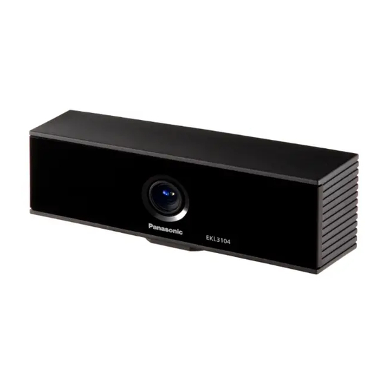
- Page 1 3D Image Sensor Model No. EKL3104 User’s Manual Version 1.20 2010.9.30 1/15...
-
Page 2: Table Of Contents
11.Special Notice ………………………………………….. 14 12.Modification History ………………………………….. 15 Notice ○ This manual and the software are copyrighted by Panasonic Electric Works Co., Ltd. ○ Reproduction of this manual in any form without prior approval is strictly prohibited. ○ Windows ® ®... -
Page 3: Safety Precautions
1.Safety Precautions THESE WARNINGS MUST BE STRICTLY OBSERVED TO PREVENT INJURY TO HUMANS OR DAMAGE TO PROPERTY. Warning MISUSE OF THIS PRODUCT MAY RESULT IN DEATH OR SERIOUS INJURY. Our company is committed to making products of the highest quality and reliability. Nevertheless, all electrical components are subject to natural deterioration, and durability or characteristics of a product will depend on the operating environment and conditions of use. -
Page 4: Operating Precautions
2.Operating Precautions 2.1 Basic Precautions The 3D Image Sensor calculates the distance to a target by measuring the “Time-of-Flight” of near-emitted infrared rays. Efficiency and reliability of the system may vary depending on actual operating conditions. Always consider the following factors: 1) High reflectance target: For example if the target is close to the sensor (closer than 1.2m(3.94ft)) or in case the sensor receives light reflected by a mirror, the amount of power received increases... -
Page 5: Other Precautions
5) The USB drivers, range image display software, library for application software development and installation manual are copyrighted by Panasonic Electric Works Co., Ltd. (“PEW”). Moreover, PEW provides the software as is, with no warranty as to its functionality, and disclaims any liability or responsibility for damage resulting from its use. -
Page 6: Included Items
5.Included Items ・Sensor unit ・Fall prevention wire, installation washer, installation screw ・Wiring fixation cramp, installation screw ・Password for software download ※The below software and manuals can be downloaded on the official home page. ・USB Drivers (XP,Vista) (Dimagerusb.inf、Dimagerusb.sys) ・Range Image Display Software (DigiCapUSB.exe) ・Library for Application Software Development (Dimagerdll.h、Dimagerdll.lib、Dimagerdll.dll) ・User’s Manual (this document) -
Page 7: Device Installation
7.Device Installation 7.1 System Composition 1) Recommended configuration (PC) ・OS :Windows ® XP(Service Pack1, Service Pack2 , Service Pack3) 32bit ® Windows Vista SP1 32bit ・CPU :Pentium ® ® 4, Pentium M 1GHz or more ※At least one available USB 2.0 port 2) AC Adaptor(Not provided with the product)... - Page 8 ■Wiring Fixation Cramp Installation Method Use the wiring fixation cramp to prevent disconnection of the USB and power supply connectors. 1) Plug-in the USB and power supply connector into the sensor unit. 2) Cross the cables and attach the wiring fixation cramp at the intersection. Use the provided M3 screw to fix the cramp to the sensor unit.
-
Page 9: Startup And Shutdown Procedures
8.Startup and Shutdown Procedures 8.1 Startup Procedure The following screenshots are from Windows XP. The process is the same for windows Vista. 1) Connect the USB of the PC and 3D image sensor. 2) Turn on the power supply of the 3D image sensor. *Turn on the power supply of the 3D image sensor only after the PC has been turned on. - Page 10 5) Designate the location of the downloaded Dimagerusb.ini and Dimagerusb.sys and click "Next." (The screen shows an example where the above files are stored in the C: ¥Dimager folder.) 6) Found New Hardware Wizard is displayed, and then hardware Installation is displayed. Click "Continue Anyway."...
- Page 11 7) Completing the Found New Hardware Wizard is displayed in the Found New Hardware Wizard, and the install is complete. *This installation is omitted at the second and all subsequent connections. However, for PCs with multiple USB ports, this recognition/setting change window may appear again if you insert the USB cable into another USB port and switch the power on.
-
Page 12: Specifications
9.Specifications 9.1 Dimensions Height:54mm Width:170mm Depth:49mm (except protuberance) 9.2 Basic Specifications Value Special Mention For a 0 lx ambient illumination 1.2m ~ 9.0m and a 90% near-infrared reflectance of Operating Range target object 3.94ft~29.53ft (20fps) Horizontal Approx.60° - Field of View Vertical Approx.44°... -
Page 13: Provision On Export Trade Control
4) In the event CUSTOMER breaches any provision of this Article, CUSTOMER shall be liable for any and all direct and indirect damages incurred by Panasonic Electric Works Co., Ltd. ("PEW") arising from such breach, and, notwithstanding anything herein contained to the contrary, PEW shall have the right to terminate this AGREEMENT forthwith without any liability to CUSTOMER. -
Page 14: Special Notice
11.Special Notice As improvements are continually being made, the specifications or design of this product are subject to change without notice. Please strictly follow the “Safety Precautions” and “Operating Precautions” on the specifications sheet. Normal functioning cannot be expected if used in environments or conditions other than those specified above. -
Page 15: Modification History
X-ON Electronics Largest Supplier of Electrical and Electronic Components Click to view similar products for manufacturer: panasonic Other Similar products are found below : ECE-A1HKAR47 ELC-09D151F HC2-H-DC48V-F HL2-HP-AC120V-F HL2-H-DC12V-F HL2-HP-DC12V-F HL2-HP-DC6V-F HL2-HP- DC24V-F HL2-H-DC110V-F HC4-H-DC24V HL2-HTM-DC24V-F HL2-HTM-AC24V-F HC4-H-AC24V HC4-H-AC120V HC4-H-DC12V...
Need help?
Do you have a question about the D-IMager EKL3104 and is the answer not in the manual?
Questions and answers