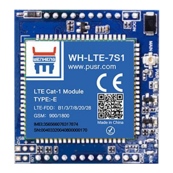
Summary of Contents for USR IOT WH-LTE-7S1-E
-
Page 1: Wh-Lte-7S1-E Hardware Manual
Technical Support: WH-LTE-7S1-E Hardware Manual Document version: V1.0.0 www.usr.cn... -
Page 2: Table Of Contents
WH-LTE-7S1-E Hardware Manual Technical Support: WH-LTE-7S1-E Hardware Manual..........................1 1. Overview..................................3 2. Introduction..................................3 2.1. Specifications..............................3 2.2. System Diagram..............................4 2.3. Pins Definition..............................5 2.4. Evaluation Board..............................6 3. Application Interfaces..............................7 3.1. Power Interface..............................7 3.2. USB Interface..............................8 3.3. -
Page 3: Overview
This document describes the pin definition, electrical characteristics and structural dimensions of the WH-LTE-7S1-E module. Combined with this document and other application documents of WH-LTE-7S1-E module, users can quickly embed the module in various terminal devices to design mobile communication application schemes. -
Page 4: System Diagram
Base station geolocation Support FTP upgrade Support Support 2.2. System Diagram WH-LTE-7S1-E uses a double inline package design, offers multiple communication interfaces: POWER, Reset, Reload, work status indicators, SIM, USB, UART and so on. Jinan USR IOT Technology Limited www.pusr.com... -
Page 5: Pins Definition
USB Power Working status indicator, flashes. The high and low WORK level change every second. POWER KEY Power on and off, low level off. Power GND. Power GND. DCIN 5-16V power. DCIN 5-16V power. Jinan USR IOT Technology Limited www.pusr.com... -
Page 6: Evaluation Board
RELOAD and RST pins are compatible with 3.3V and 5V input. NC: pin is not in use. I/O stands for bidirectional data transfer pins. 2.4. Evaluation Board In order to facilitate application development with 7S1-E conveniently, we supplies the evaluation board (EVB)--USR-7SX-EVK. Jinan USR IOT Technology Limited www.pusr.com... -
Page 7: Application Interfaces
Technical Support: 3. Application Interfaces 3.1. Power Interface WH-LTE-7S1-E supports DC 5~16V or DC 3.4~4.2V power supply. 3.1.1.DC 5~16V Power Supply Connecting pins 13 and 14 with 5~16V power supply. When designing the product, please ensure that the peripheral circuit can provide sufficient power supply capacity, and strictly control it within 5V ~ 16V. It is recommended to add 220uF electrolytic capacitor at the front end of the pin interface to increase the stability of the power supply. -
Page 8: Usb Interface
3.3. UART Interface WH-LTE-7S1-E supports below baud rate: 1200,2400,4800,9600,19200,38400,57600,115200,230400,460800,921600 When the I/O of the user's MCU is not 3.0V, level matching is needed to achieve communication with WH-LTE-7S1-E module. The conversion circuit is as follows: Jinan USR IOT Technology Limited www.pusr.com... -
Page 9: Sim Interface
V_PAD is the module serial power pin (3.0V). VDD is the user’s MCU level. For triodes, S9014/J6 of JCET Group is recommended, or other devices of the same specification. 3.4. SIM Interface The module provides an ISO 7816-3 standard SIM card interface that automatically recognizes 3.0V and 1.8V SIM cards. Jinan USR IOT Technology Limited www.pusr.com... - Page 10 WH-LTE-7S1-E Hardware Manual Technical Support: WH-LTE-7S1-E has integrated SIM card function and can be used directly, users can also design according to the needs with the SIM pins. Recommendations: In order to prevent the damage of USIM card and chip caused by static electricity, it is necessary to add TVS tube for electrostatic protection.
-
Page 11: Indicators
WH-LTE-7S1-E Hardware Manual Technical Support: 3.5. Indicators WH-LTE-7S1-E provides LED to display the working status of the module. Symbol Description Type voltage LINKA Socket A status 3.0V LINKB Socket B status 3.0V WORK Module work status 3.0V Network status 3.0V... - Page 12 Note: If the user needs to read the indicator light level, cannot directly connect the MCU pins to the module’s indicator light pins, need to do the level matching. VCC is the user level. Jinan USR IOT Technology Limited www.pusr.com...
-
Page 13: Reset/Reload
Technical Support: 3.6. Reset/Reload WH-LTE-7S1-E supports hardware reset and restore the factory settings: RESET: Pull down the “RESET” pin for 0.5s, then pull up or open it. Reload: Pull down for 3~15s, then pull up or open it to restore the factory settings. -
Page 14: Electrical Characteristics
3.0V U(S)IM: Class B, USIM_VDD=3.0V For RST, POWER KEY and others: 1.8V I/O voltage parameters: Symbol Parameter Unit High-level input voltage 1.17 Low-level input voltage -0.4 0.63 High-level output voltage 1.35 Low-level output voltage 0.45 Jinan USR IOT Technology Limited www.pusr.com... -
Page 15: Io Current Range
Unit High-level input voltage Low-level input voltage High-level output voltage Low-level output voltage 0.45 4.4. IO Current Range IO pin Maximum input current Maximum drive current IO current 5. Mechanical Characteristics 5.1. Reflow Soldering Jinan USR IOT Technology Limited www.pusr.com... -
Page 16: Dimensions
WH-LTE-7S1-E Hardware Manual Technical Support: 5.2. Dimensions Jinan USR IOT Technology Limited www.pusr.com...


Need help?
Do you have a question about the WH-LTE-7S1-E and is the answer not in the manual?
Questions and answers