
Related Manuals for USR IOT USR-ES1


Summary of Contents for USR IOT USR-ES1
-
Page 1: Spi To Ethernet Module
SPI to Ethernet Module www.usr.so SPI to Ethernet Module (USR-ES1) File version: Ver 1.0 Jinan USR IOT Technology Limited 1 / 11 tec@usr.cn... -
Page 2: Table Of Contents
4.1 IAR Embedded............................10 5. Application Structure............................10 6. FAQ..................................11 6.1 No communication.............................11 6.2 IAR routine compilation errors.........................11 6.3 No communication, cable connection does not recognize..............11 7. Contact...................................11 8. Update History..............................11 Jinan USR IOT Technology Limited 2 / 11 tec@usr.cn... -
Page 3: Quick Start
Network cable, USB to TTL converter. The hardware connection diagram as follows: Diagram 1-1 Connection Diagram Because here the use of the 3.3V micro controller system, so the middle without adding a level conversion. Jinan USR IOT Technology Limited 3 / 11 tec@usr.cn... - Page 4 Diagram 1-2 Connection with an Core Board Routine parameters module, the default for the: IP Address: 192.168.1.101 The subnet mask: 255.255.255.0 GateWay Address: 192.168.1.1 Diagram 1-3 The Sample Project Ping module’s IP address. Diagram 1-4 Ping Jinan USR IOT Technology Limited 4 / 11 tec@usr.cn...
-
Page 5: Introduction
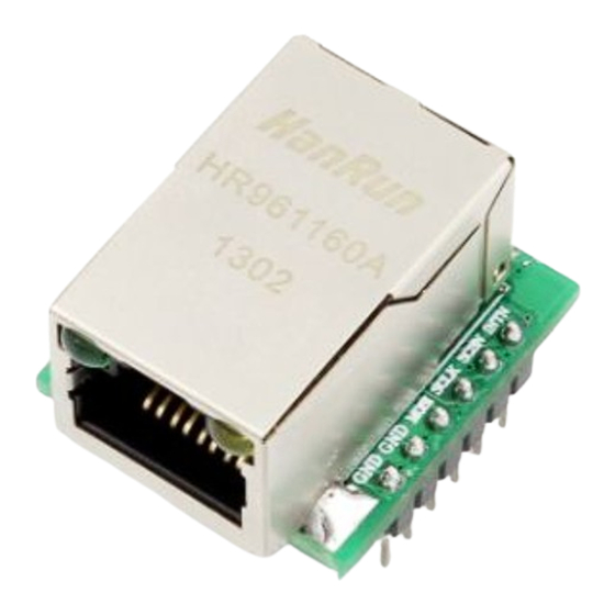
Diagram 1-5 Module’ webpage 2. Introduction USR-ES1 is the Ethernet module of a SPI interface, interface is TTL level of 3.3V, power supply voltage of +3.3V, please ensure that the current is not less than 200mA, voltage is continuous and stable +3.3V. -
Page 6: Characteristic
28.5 * 23 * 24 Diagram 2-1 Characteristic 2.3 Part Number Type characteristic remarks USR-ES1 The SPI communication interface, pin package, TTL level 3.3V Diagram 2-1 Characteristic 2.4 Packing List USR-ES1 module * 1 Jinan USR IOT Technology Limited 6 / 11 tec@usr.cn... -
Page 7: Hardware Description
SPI to Ethernet Module www.usr.so 3. Hardware Description 3.1 Hardware A total of two sets of pins, the first group and the second group. 3.2 Pin Definition Jinan USR IOT Technology Limited 7 / 11 tec@usr.cn... - Page 8 PLL logic to be stable. SPI Master In Slave Out 2 - 6 MISO This pin is used to SPI MISO signal pin. Diagram 3-1 Pin Diagram Jinan USR IOT Technology Limited 8 / 11 tec@usr.cn...
-
Page 9: Dimensions
SPI to Ethernet Module www.usr.so 3.3 Dimensions Symbol Dimension(mm) Symbol Dimension(mm) 23.00 1.34 20.32 (2.54 x 8) 2.50 (+/- 0.50) 1.34 6.40 2.11 2.54 16.10 5.80 2.11 25.00 Diagram 3-2 Dimensions 3.4 Reset Timing Jinan USR IOT Technology Limited 9 / 11 tec@usr.cn... -
Page 10: Develop Tools
IAR embedded workbench. currently support ARM IDE. (other IDE tools also support ARM IDE, for example, such as the Keil). software version is for ARM 5.41 embedded workbench. On how to use IAR, see the IAR manual. 5. Application Structure Diagram 5-1 Connection Diagram Jinan USR IOT Technology Limited 10 / 11 tec@usr.cn... -
Page 11: Faq
Such as modules connected module, require the use of cross line, module. The router or switch requires the use of straight line. 7. Contact Company: Jinan USR IOT Technology Limited Address: 1-728, Huizhan Guoji Cheng, Gaoxin Qu, Jinan, Shandong, China Tel:...
Need help?
Do you have a question about the USR-ES1 and is the answer not in the manual?
Questions and answers