Advertisement
Quick Links
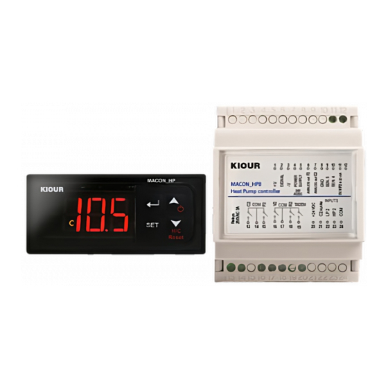
Control device CHILLER / heat pump for 1 or 2 circuits with 2 or 4 compressors,
with analog outputs 0-10 Volt in compressors and fans.
Models: MACON_HP (panel), MACON_HPR (rail) (1
DESCRIPTION
MACON_HP controller is suitable for controlling a chiller or 2-circuit heat pump. Available in 28x70mm box or in 70mm rail box. The second circuit (MACON_HPB) is
available in a 70mm rail box and is connected to the main unit via three cables.
MACON_HP (1st circuit) has the following specifications:
3 analog inputs for measuring temperature with range -50 ÷ +150°C
1 analog high pressure input (HP1) 4-20 mA for transmitter
SENsor 1. Water input circuit 1. Operation thermostat HEATING - COOLING
SENsor 2. Water output. Safety thermostat Νo1. Resistance Νo1
SENsor 3. Defrost control C1 (Compressor 1
6 digital inputs:
1st input Terminal block 15. ΟΝ-OFF device from a remote switch
2
input Terminal block 16 HEAT-COOL from a remote switch
nd
3
input Terminal block 17 HP1. High pressure 1
rd
4
th
input Terminal block 18 LP1. Low pressure 1
5
th
input Terminal block 19 C1. Thermal of 1
6
input Terminal block 20 FLOW SWITCH.
th
7 relay outputs 250VAC 5Amp: pump relay, compressor C1, valve V1,
resistance R1, fan FAN 1, alarm, compressor C1b Tadem or capacitive.
2 analog output 0-10 Volt Compressor C1 (Terminal blocks 25, 28), and
for the fan FAN1 (Terminal blocks 25, 27).
CONNECT TO NETWORK
The device can connect to a PC via network RS485 or to a Remote Control via four cables.
Connect to a PC: CAMIN software can monitor all temperatures, compressors relays, alarms, parameters, while sending SMS and emails in case of an alarm.
More than 250 devices can connect to this network.
Connect to a Remote Control device: it displays on screen whatever is displayed on the main device and it has full access from the keyboard to the main device.
It can be installed up to 500 meters away from the main device.
PARAMETERS
Parameters are separated in two groups: 120 main parameters and 16 secondary parameters (A1-A16). Two of the main and 16 of the secondary parameters are easy
accessible. For the rest we have to enter in the parameter Cod = 22 to have access to all the parameters
TECHNICAL SPECIFICATIONS
Power supply: 24 VAC/DC 50/60 Hz 10W
Connection with terminal blocks 28-16 AWG 1.5 mm
7 relays 250VAC 5A/3A Resistive Load in MACON_HP
5 relays 250VAC 5A Resistive Load in MACON_HPΒ
Operation temperature: -10 ÷ +50 °C
ON/OFF DEVICE
Press
for 4 seconds to toggle the device between ON/OFF state if the parameter is set to Grc=0
If ON-OFF input No 15 is activated or if the parameters are under programming, this function is canceled.
HEATING – COOLING OPERATION
Press
for 4 seconds to toggle the operation between heating and cooling or cooling and heating mode if parameter is set to GrH=0.
If the input No 16 Heating-Cooling is activated or the parameters are under programming, this operation is cancelled.
dFrost
Pressing the SET button for 5 sec starts dFrost on both circuits. The display shows the message dF1 and dF2 every 2 sec, for a fraction of a second, which means that
circuits 1 and 2 do dFrost.
RESET ALARMS
Pressing
to reset the alarms: this feature is active even during programming the parameters.
PROGRAMMING PARAMETERS
Press
to enter or exit the parameters menu.
The first parameter "SCo" is displayed and with the
Press SET to display the parameters value and adjust it with the
Press
to confirm the new value and display the parameters name.
Press SET to cancel the new value and revert to the parameters name.
NOTE: for safety reasons all parameters as presented to the parameters table are not displayed. We must enter parameter Cod=22 to access full parameters menu.
circuit) and MACON_HPB (rail), (2
st
)
st
circuit
st
st
circuit
st
circuit compressor
2
,
we scroll into the parameters menu.
,
.
nd
MACON_HPB (2
circuit) has the following specifications:
nd
2 analog inputs for measuring temperature with range -50 ÷ +150°C
1 analog high pressure input (HP1) 4-20 mA for transmitter
SENsor 4. Water output 2
circuit. Safety thermostat Νo2. Resistance Νo2
nd
SENsor 5. Defrost C2 control (2
3 digital outputs:
7
th
input Terminal block 23 HΡ2. High pressure 2
8
input Terminal block 22 LP2. Low pressure 2
th
9
input Terminal block 21 C2.
th
5 relay outputs 250VAC 5Amp: compressor relay C2, valve V2, resistance R2, fan
FAN 2, compressor C2b Tadem or capacitive.
2 analog output 0-10 Volt Compressor C2 (Terminal blocks 7, 8) and for the
fan FAN2 (Terminal blocks 6, 8).
.
Check relevant table on page 2.
Storage temperature: -20 ÷ +80 °C
MACON_HP is mounted on a panel / Dimensions 28x70x75mm
MACON_HPΒ is mounted on a Ω rail / Dimensions 70x90x65mm
It is suggested using a safety switch 1Α (not included)
Maximum consumption for each device 10 Watt
.
circuit) V.2.1
circuit.)
nd
nd
circuit
circuit
nd
Thermal of 2
circuit compressor
nd
Advertisement

Subscribe to Our Youtube Channel
Related Manuals for KIOUR MACON HP


Summary of Contents for KIOUR MACON HP
- Page 1 Control device CHILLER / heat pump for 1 or 2 circuits with 2 or 4 compressors, with analog outputs 0-10 Volt in compressors and fans. Models: MACON_HP (panel), MACON_HPR (rail) (1 circuit) and MACON_HPB (rail), (2 circuit) V.2.1 DESCRIPTION MACON_HP controller is suitable for controlling a chiller or 2-circuit heat pump. Available in 28x70mm box or in 70mm rail box. The second circuit (MACON_HPB) is available in a 70mm rail box and is connected to the main unit via three cables.
- Page 2 DISPLAY AND RESET OPERATION HOUR OF COMPRESSORS Press to display the first parameter SCo. By pressing up arrow button parameters from A16 to A1 are displayed. From A10-A14 are the operating hours of compressors and pump. When the parameter name is displayed, for eg. h P and press SET the pump operating hours are displayed and by pressing simultaneously resets the hours.
- Page 3 PARAMETERS DESCRIPTION DEFAULT Temperature ending defrost With the parameter dto = 1 the defrost ends when it reaches this temperature in less than the 15.6 °C maximum duration of the defrost. With the parameter t3E = 1 it functions as a differential (differential = dEn - dbE) safety thermostat of the temperature SEn3, SE55 Over this temperature, the fan is ON during defrost.
- Page 4 PARAMETERS DESCRIPTION DEFAULT Pump-Compressor Time. Compressor start time after pump. Compressor-Pump Time. OFF time of the pump after OFF of the compressor. Intermittent operation of the pump when the compressor is OFF. The tPO parameter works in conjunction with the GFr parameter. GFr = 0 deactivates the function of the tPO parameter. If GFr = 1 and tPO = 1-100 min, the pump restarts after the time specified by the parameter (OFF time) and remains ON at the time specified by the parameter tPd, (time ON).
-
Page 5: Alarm Table
PARAMETERS DESCRIPTION DEFAULT C2. Lower analog output voltage. Compressor C2 of the 2 circuit. The analog signal 0-10 Volt corresponds consistently to C2. Values from 0 to 4.0 Volts. The analog output will be between C2U - Volt C2d in a temperature range defined by the parameter C2H or C2C. For example, C2U - C2d = 7 and C2H = 3 and SHt =45°C, the voltage will change 10-3Volt from 42 ÷... - Page 6 MESSAGE BOARD Display does not flash when displaying messages. Displays the message sequentially for 0.2 seconds and the temperature for 2 seconds. Drainage procedure of the 1 circuit after deFrost. Drainage procedure of the 2nd circuit after deFrost. dFrost is running on the 1 circuit dFrost is running on the 2 circuit.
- Page 7 The same applies to FAN 2, respectively with the parameters F2d, F2U, F2C...
- Page 8 In case of using analog signals, the use of an isolation transformer in the power supply is recommended. Temperature sensor No 1. Water inlet, circuit 1. Thermostat operation: HEATING-COOLING Temperature sensor No 2. Water outlet. Safety thermostat No. 1. Resistance No. 1. Temperature sensor No 3.
- Page 9 The device is under two year’s guarantee. The guarantee is valid only if the manual instructions have been applied. The control and service of the device must be done by an authorized technician. The guarantee covers only the replacement or the service of the device. preserves the right to adjust its products without further notice. V2.1.080721 392 Mesogeion Avenue Agia Paraskevi 153 41 Τ: 210 6533730 F: 210 6546331 info@kiour.com www.kiour.com...
Need help?
Do you have a question about the MACON HP and is the answer not in the manual?
Questions and answers