Table of Contents
Advertisement
Available languages
Available languages
Quick Links
OWNER'S MANUAL
C
C
C
C
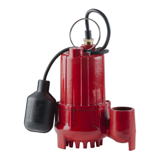
Cast Iron Sump Pumps
a
a
a
s
s
t
t
I
I
r
r
o
o
n
n
S
S
u
u
m
m
This submersible pump is for use in basins or lift stations and is suit-
able for pumping clear water and other non-explosive, non-corrosive
liquids. Do not use the pump in applications where sewage or any
other debris (gravel, sand, floating debris, etc.), abrasives, or corro-
sives are present.
The pump motor is equipped with an automatic resetting thermal
protector, and may restart unexpectedly. Thermal Protector tripping is
an indication of motor overloading or overheating, which can be
caused by application issues such as an obstructed pump impeller,
float stuck in the ON position, pump running dry, pump air-locked,
pump short cycling, excessively high or low voltage supply, or possi-
bly the pump, motor, bearings, or seal have reached the end of their
useful life.
This product is covered by a Limited Warranty for a period of 3 years from the date of original purchase by
the consumer. For complete warranty information, refer to www.redlionproducts.com, or call Technical
Support for a printed copy.
Specifications
Model
Item Number
RL-SC33T
RL-SC33V
RL-SC50T
RL-SC50V
Model
RL-SC33T
RL-SC33V
RL-SC50T
RL-SC50V
p
p
P
P
umps
HP
14942744
1/3
14942745
14942746
1/2
14942747
Gallons/Liters per Hour @ Height (Head)
5 ft (1.5m)
10 ft (3 m)
3000 / 11356
2460 / 9312
3840 / 14536 3000 / 11356
Volts
Amps
4.3
115
5.3
15 ft (4.5 m)
1860 / 7041
2220 / 8404
Table of Contents
INSTALLATION- - - - - - - - - - - - - - - - - - - - - - - - - -4
Typical Installation - - - - - - - - - - - - - - - - - - -4
Physical Installation- - - - - - - - - - - - - - - - - - -5
Electrical Connections - - - - - - - - - - - - - - - - -6
OPERATION TESTING - - - - - - - - - - - - - - - - - - - - -6
MAINTENANCE - - - - - - - - - - - - - - - - - - - - - - - - -7
Periodic Service - - - - - - - - - - - - - - - - - - - - -7
Cleaning Impeller and Volute - - - - - - - - - - - -9
Troubleshooting - - - - - - - - - - - - - - - - - - - - -9
Replacement Parts - - - - - - - - - - - - - - - - - - -9
EN
EN
ON Levels
13" (33.0 cm)
7" (17.8 cm)
2.25" (5.7 cm)
13" (33.0 cm)
5" (12.7 cm)
7" (17.8 cm)
2.25" (5.7 cm)
20 ft (6.1 m)
960 / 3634
1440 / 5451
English
English
English
English
Off Levels
5" (12.7 cm)
Shut Off
25 ft (7.6 m)
28 ft (8.5 m)
Advertisement
Chapters
Table of Contents

Related Manuals for red lion RL-SC33T


Summary of Contents for red lion RL-SC33T
-
Page 1: Table Of Contents
For complete warranty information, refer to www.redlionproducts.com, or call Technical Support for a printed copy. Specifications Model Item Number Volts Amps ON Levels Off Levels RL-SC33T 14942744 13” (33.0 cm) 5” (12.7 cm) RL-SC33V 14942745 7” (17.8 cm) 2.25” (5.7 cm) RL-SC50T 14942746 13”... - Page 2 Failure to comply with national and local electrical and plumbing codes and within Red Lion recommendations may result in elec- trical shock or fire hazard, unsatisfactory performance, or equipment failure.
- Page 3 SAFETY INSTRUCTIONS Table of Contents Risk of bodily injury, electric shock, or equipment damage. • This equipment must not be used by children or persons with reduced physical, sensory or mental abilities, or lacking in experience and expertise, unless supervised or instructed. Children may not use the equipment, nor may they play with the unit or in the immediate vicinity.
-
Page 4: Installation
INSTALLATION Typical Installation INSTALLATION Typical Installation SEPARATE PROTECTED AND GROUNDED SERVICE OUTLET, 4’ FROM FLOOR MINIMUM FLOAT SWITCH POWER CORD PUMP POWER CORD GATE VALVE TETHER LENGTH: 3-1/2” (89 mm) CHECK VALVE On: 13” (330 mm) Off: 5” (127mm) DISCHARGE PIPE NO SMALLER THAN PUMP OUTLET 2”... -
Page 5: Physical Installation
• For RL-SC33V and RL-SC50V models, the basin must be 15” (38.1 cm) in diameter. • For RL-SC33T and RL-SC50T models, the basin must be 18” (45.7 cm) in diameter. • Place as close as possible to a water source to minimize suction piping length. -
Page 6: Electrical Connections
OPERATION TESTING Electrical Connections Electrical Connections High voltages capable of causing severe injury or death by electrical shock are present in this unit. • Be certain that this pump is connected to a circuit equipped with a ground fault circuit interrupter (GFCI) device if required by code. -
Page 7: Maintenance
MAINTENANCE Periodic Service 4. Run water into the basin until the pump is activated. 5. Make sure the pump and its float switch are functioning as intended. • Confirm that no potential obstructions exist that could inhibit switch operation. NOTE: It is normal for a stream of water to spray from the air relief bleed hole in the pump's plumbing. -
Page 8: Cleaning Impeller And Volute
MAINTENANCE Cleaning Impeller and Volute Cleaning Impeller and Volute 1. Disconnect power to the pump. 2. Disconnect the pump from the discharge plumbing. 3. Remove the bolts that hold the volute to the base. 4. Separate the volute from the motor housing. IMPORTANT: Do not remove the motor housing bolts or screws. - Page 9 Pour obtenir des informations complètes sur la garantie www.redlionproducts.com. Spécifications Modèle Numéro d'article Volts Ampères SUR le niveau ARRÊTEZ le niveau RL-SC33T 14942744 33,0 cm (13 po.) 12,7 cm (5 po.) RL-SC33V 14942745 17,8 cm (7 po.) 5,7 cm (2,25 po.)
- Page 10 équipements et les procédures appropriés. Le non-respect des codes électriques nationaux et locaux et des recommandations de Red Lion peut entraîner un risque de choc électrique ou d’incendie, des problèmes de performance, ou une panne de l’équipement.
- Page 11 CONSIGNES DE SÉCURITÉ Table des matières Risque de blessure, de choc électrique ou de dégâts matériels. • Cet équipement ne doit pas être utilisé par des enfants ou des personnes aux capacités physiques, sensorielles ou cognitives réduites, ou par des personnes n’ayant pas l’expérience ou l’expertise appropriée, sauf si ces per- sonnes sont supervisées ou ont reçu des instructions à...
-
Page 12: Installation
INSTALLATION Installation typique INSTALLATION Installation typique PRISE DE COURANT DE MISE À LA TERRE À PROTECTION SÉPARÉE À UNE DISTANCE MINIMALE DE 4 PI DU SOL FIL D’ALIMENTATION DE L’INTERRUPTEUR À FLOTTEUR CORDON D’ALIMENTATION DE LA POMPE CLAPET DE LA VANNE CLAPET DE RETENUE FIL DE L’INTERRUPTEUR : 89 mm (3 1/2 po) marche : 330 mm (13 po) -
Page 13: Installation Physique
• Pour les modèles de RL-SC33V et RL-SC50V, le bassin doit être 38,1 cm (15 pi) de diamètre. • Pour les modèles de RL-SC33T et RL-SC50T, le bassin doit être 45,7 cm (18 pi) de diamètre. • Placez la pompe plus près possible de la source d’eau, afin de réduire au minimum la longueur de la tuyauterie d’aspiration. -
Page 14: Connexions Électriques
INSTALLATION Connexions électriques 8. Confirmez que la pompe fonctionne comme prévu. Consultez « Test de fonctionnement » page REMARQUE : Il est normal qu’un filet d’eau s’échappe de l’orifice de prise d’air de la plomberie de la pompe. (L'eau gicle de l'orifice d'un boulon situé à la base de l'appareil.) Assurez-vous que ce filet est recueilli à... -
Page 15: Test De Fonctionnement
TEST DE FONCTIONNEMENT Connexions électriques TEST DE FONCTIONNEMENT Risque de blessure corporelle ou de dommage à la pompe ou d’autres équipements. • Il convient de faire fonctionner la pompe en mode manuel et continu seulement en cas d’urgence ou lorsqu’un volume d’eau important doit être pompé. -
Page 16: Entretien
ENTRETIEN Service périodique ENTRETIEN Risque de blessure grave ou de mort par électrocution, température élevée ou liquide sous pression. • Avant d’effectuer des travaux sur la pompe ou l’interrupteur, vous devez toujours débrancher le cor-don d’ali- mentation de la pompe, en plus de retirer le fusible ou de couper le disjoncteur. •... -
Page 17: Dépannage
ENTRETIEN Dépannage Dépannage Problème Causes probables Mesure Corrective La pompe n’est pas branchée. Branchez la pompe. Disjoncteur éteint ou fusible retiré. Activez le disjoncteur ou remplacez le fusible. La pompe ne démarre Moteur défectueux. Remplacer la pompe. L'interrupteur à flotteur ou d'autres com- mandes de niveau ne fonctionnent pas cor- Consultez le manuel du propriétaire de l'interrupteur à... - Page 18 Pour l’aide technique, entrez s’il vous plaît en contact : 888.885.9254 | redlionproducts.com 998495 Rév. 005 11/21 Droits d’auteur © 2021, Franklin Electric, Co., Inc. Tous droits réservés.
- Page 19 Para obtener información completa sobre la garantía, consulte www.redlionproducts.com. Especificaciones Número de Amperio Modelo Vatios Nivel ON Nivel OFF artículo RL-SC33T 14942744 33.0 cm (13 pulg) 12.7 cm (5 pulg) RL-SC33V 14942745 17.8 cm (7 pulg) 5.7 cm (2.25 pulg) RL-SC50T 14942746 33.0 cm (13 po)
- Page 20 El hecho de no cumplir con los códigos eléctricos nacionales y locales y con las recomendaciones de Red Lion puede provocar peligros de descarga eléctrica o incendio, desempeños insatisfactorios o fallas del equipo.
- Page 21 INSTRUCCIONES SOBRE SEGURIDAD Indice Riesgo de lesiones corporales, descargas eléctricas o daños al equipo. • Este equipo no deben usarlo niños ni personas con capacidades físicas, sensoriales o mentales reducidas, ni aquellos que carezcan de experiencia y capacitación, salvo que estén bajo supervisión o instrucción. Los niños no podrán usar el equipo ni jugar con la unidad o en las cercanías inmediatas.
- Page 22 INSTALACIÓN Instalación típica INSTALACIÓN Instalación típica TOMACORRIENTES DE SERVICIO CONECTADO A TIERRA Y PROTEGIDO SEPARADO POR LO MENOS A 4 PIES DEL SUELO. CORDÓN DE LA CORRIENTE DEL INTERRUPTOR DEL FLOTANTE CABLE DE POTENCIA DE LA BOMBA VÁLVULA DE LA COMPUERTA VERIFIQUE VÁLVULA PRISIONERO DE : 89 mm (3-1/2 pulg.)
- Page 23 • Para los modelos RL-SC33V y RL-SC50V, la cuenca debe tener un diámetro de 38.1 cm (15 pulg.). • Para los modelos RL-SC33T y RL-SC50T, la cuenca debe tener un diámetro de 45.7 cm (18 pulg.). • Plazca la bomba lo más cerca posible de la fuente de agua para minimizar la longitud de las tuberías de succión.
- Page 24 INSTALACIÓN Conexiones eléctricas 8. Confirme que la bomba está funcionando según lo previsto. Consulte “Prueba de operación” en la página NOTA: Es normal que una corriente de agua rocíe desde el orificio de purga de aire en la tubería de la bomba. Confirme que este aerosol es capturado dentro de la cuenca. 9.
- Page 25 PRUEBA DE OPERACIÓN Conexiones eléctricas PRUEBA DE OPERACIÓN Riesgo de lesiones corporales, descargas eléctricas o daños al equipo. • La operación manual y continua de la bomba se debe utilizar solo en caso de emergencia o cuando haya que bombear un gran volumen de agua. La bomba se debe monitorear permanentemente durante la operación y se debe desconectar de la alimentación antes de que funcione en vacío.
- Page 26 MANTENIMIENTO Servicio periódico MANTENIMIENTO Riesgo de lesiones graves o muerte por descarga eléctrica, temperaturas elevadas o líquidos presurizados. • Siempre desenchufe el cable eléctrico de la bomba y desconecte la alimentación eléctrica antes de realizar el mantenimiento de la bomba o del interruptor. •...
- Page 27 MANTENIMIENTO Solución de problemas Solución de problemas Problema Causas probables Acción correctiva La bomba no está conectada al suministro Conecte la bomba a un circuito dedicado que esté equipado eléctrico. con GFCI. Disyuntor apagado o sin fusible. Encienda el disyuntor o reemplace el fusible. La bomba no se enciende Motor defectuoso.
- Page 28 Para la ayuda técnica, por favor póngase en contacto: 888.885.9254 | redlionproducts.com 998495 Rev. 005 11/21 Copyright © 2021, Franklin Electric, Co., Inc. Todos los derechos están reservados.
Need help?
Do you have a question about the RL-SC33T and is the answer not in the manual?
Questions and answers