Advertisement
+050001320 - rel. 1.0 date 13.09.2007
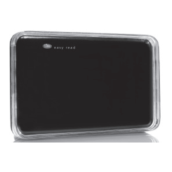
EW00S**00*:
easy read sensore wireless di temperatura ed umidità/easy read wireless temperature and humidity sensor
Dimensioni (mm)/Dimensions (mm)
121,55
Dip-switch/Dipswitches
A
B
DIP SWITCH
ON
OFF
LSB
1 2 3 4 5 6 7 8
MSB
C
Caratteristiche generali
Il sensore EasyRead, dispositivo elettronico che fa parte del sistema "EasyWay", permette di
comunicare con l'Access Point e di inviare la temperatura e l'umidità, a seconda del modello scelto, ai
sistemi di supervisione CAREL.
Il prodotto può essere commercializzato in tutti i paesi della Comunità Europea.
Per tutti gli altri paesi si verifi chi la Normativa vigente in relazione alle caratteristiche radio.
Montaggio a parete
Il sensore può essere appoggiato ad una superfi cie o fi ssato ad una parete tramite il supporto plastico
contenuto nella confezione, per un corretto montaggio a parete seguire le seguenti istruzioni:
• Eseguire i due fori nella parete come mostrato in Fig. 3 seguendo gli accorgimenti racchiusi nella
sezione "Avvertenze generali";
• Tramite una forbice o un tronchesino, eliminare il particolare "A" in plastica mostrato in Fig. 4 se si
vuole che lo strumento possa essere sganciato dal supporto senza l'utilizzo di un cacciavite. In caso
contrario invece non rimuovere il particolare. Per sganciare lo strumento sarà necessario un
cacciavite inserito nella posizione mostrata in Fig. 5;
• Far scorrere il terminale, in modo da agganciarlo al supporto come mostrato in Fig. 4;
• Il terminale è fi ssato alla parete ed è pronto per essere confi gurato seguendo le indicazioni per
l'installazione.
Installazione
Il sensore è alimentato a batteria, che in condizioni normali di funzionamento, ne garantisce la durata
per alcuni anni.
Prima di accendere lo strumento accertarsi di aver eseguito le seguenti istruzioni:
• Aprire il vano batteria togliere la batteria e tramite il dip switch assegnare un indirizzo tra 16 e 199.
Indirizzo CAREL
0...15
16
17
18
19
20
...
199
42,5
(*) È possibile settare l'indirizzo ma il dispositivo non potrà essere associato all'Access point/ripetitore.
Utilizzo della calcolatrice per decodifi ca indirizzo 157:
Decimale: 157
Fig. 1
Conversione in notazione binaria: (MSB) 10011101 (LSB)
Invertire la stringa (10111001) e settare i dip-switches da 1 a 8.
Dip Switches
1 2 3 4 5 6 7 8
1 0 1 1 1 0 0 1
• Inserire la batteria facendo attenzione alla polarità. Controllare che il led L1 si accenda per qualche sec.;
• Per assegnare il sensore ad una rete esistente aprire il canale di annessione premendo il tasto
dell'Access Point a cui si vuole assegnare lo strumento e i 3 led iniziano a lampeggiare (si veda la
Legenda:
documentazione dell'Access Point per maggiori informazioni su come connettere uno strumento);
A
Led L1
• Premere il tasto T1 con una punta e il led del sensore si accende per qualche secondo, mentre
B
Tasto T1
quelli dell'Access Point si accendono in sequenza. Il sensore sarà correttamente annesso
C
Vano batteria
se ad ogni singola pressione di T1 corrisponde un singolo lampeggio di L1;
• Per vedere i dati provenienti dal sensore collegare il supervisore e impostare lo stesso indirizzo
Key:
inserito sul dip switch. Dopo qualche minuto comparirà il set di variabili per il supervisore;
A
LED L1
• Se i led non si accendono come descritto, oppure il sensore non compare sul supervisore signifi ca
B
Button T1
che è stato fatto qualche errore durante l'installazione. Per re-inizializzare lo strumento si prema il
C
Battery compart.
tasto T1 per qualche secondo fi no a quando il led lampeggia. Lo strumento a questo punto è stato
sconnesso dalla rete esistente, si ripetano le operazioni a partire dall'inizio.
Fig. 2
Dip Switches
Note
1 2 3 4 5 6 7 8
x
x
x
x
x
x
x
x Indirizzi non permessi (*)
0 0 0 0 1 0 0 0
1 0 0 0 1 0 0 0
0 1 0 0 1 0 0 0
1 1 0 0 1 0 0 0
0 0 1 0 1 0 0 0
1 1 1 0 0 0 1 1
General features
The EasyRead sensor, an electronic device that is part of the "Easy Way" system, is used to
communicate with the Access Point and send the temperature and humidity readings, depending
on the model chosen, to CAREL supervisor systems.
The product may be sold in all EU countries.
For all other countries, check the legislation in force with regards to the radio specifi cations.
Wall-mounting
The sensor can be rested on a surface or fastened to the wall using the plastic support contained in
the packaging; for correct wall-mounting, observe the following instructions:
• Make two holes in the wall as shown in Fig. 3, following the details described in the section on
• Use scissors or cutting nippers to remove the plastic part "A" shown in Fig. 4 if the device needs to
be removed from the support without needing a screwdriver. Otherwise, leave the part intact, and a
screwdriver inserted in the position shown in Fig. 5 will be required to release the device;
• Slide the terminal onto the support, as shown in Fig. 4;
• The terminal is now fastened to the wall and is ready to be confi gured, following the installation
instructions.
Installation
The sensor is powered by battery, which in normal operating conditions guarantees operation for a
number of years.
Before switching the instrument one, make sure the following operations have been completed:
• Open the battery compartment, remove the battery and use the dipswitches to set an address
between 16 and 199.
CAREL address
Dipswitch
1 2 3 4 5 6 7 8
0...15
x
x
x
x
x
x
x
x
16
0 0 0 0 1 0 0 0
17
1 0 0 0 1 0 0 0
18
0 1 0 0 1 0 0 0
19
1 1 0 0 1 0 0 0
20
0 0 1 0 1 0 0 0
...
199
1 1 1 0 0 0 1 1
(*) The address can be set, however the device cannot be associated with any Access point/repeater.
Use the calculator to decode the address 157:
Decimal: 157
Conversion to binary notation: (MSB) 10011101 (LSB)
Invert the string (10111001) and set dipswitches from 1 to 8.
Dipswitches
1 2 3 4 5 6 7 8
1 0 1 1 1 0 0 1
• Insert the battery, making sure the polarity is correct. Check that LED L1 comes on for a few seconds;
• To assign the sensor to an existing network, open the connection channel by pressing the button
on the Access Point that the sensor is being connected to, and the 3 LEDs will start fl ashing (see the
documents on the Access Point for further information on how connect an instrument);
• Press button T1 with a pointed tool, the LED on the sensor comes on for a few seconds, while the
LEDs on the Access Point come on in sequence. The sensor will be correctly connected if when
pressing T1 once L1 fl ashes once;
• To see the data from the sensor, connect the supervisor and set the same address as selected by
dipswitch. After a few minutes the set of supervisor variables will be shown;
• If the LEDs do not come on as described, or alternatively the sensor is not displayed on the supervi
sor, there has been an error during installation. To re-initialise the sensor, press button T1 for a few
seconds until the LED fl ashes. The sensor has now has been disconnected from the existing
network; then repeat the operations starting from the beginning.
Note
Addresses not allowed (*)
Advertisement
Table of Contents

Subscribe to Our Youtube Channel
Related Manuals for Carel EW00S Series


Summary of Contents for Carel EW00S Series
- Page 1 Access Point and send the temperature and humidity readings, depending sistemi di supervisione CAREL. on the model chosen, to CAREL supervisor systems. Il prodotto può essere commercializzato in tutti i paesi della Comunità Europea. The product may be sold in all EU countries.
- Page 2 The customer must use the product only in the manner described in the documentation relating to the EW00SB* • • product. The liability of CAREL in relation to its products is specifi ed in the CAREL general contract conditions, Tab. 3 available on the website www.carel.com and/or by specifi c agreements with customers. Tab. 3 Note: for further information (list of supervisor models,...) see the corresponding manual +030220840...
Need help?
Do you have a question about the EW00S Series and is the answer not in the manual?
Questions and answers