Table of Contents
Advertisement
Quick Links
Advertisement
Table of Contents

Related Manuals for Riken Keiki FI-915


Summary of Contents for Riken Keiki FI-915
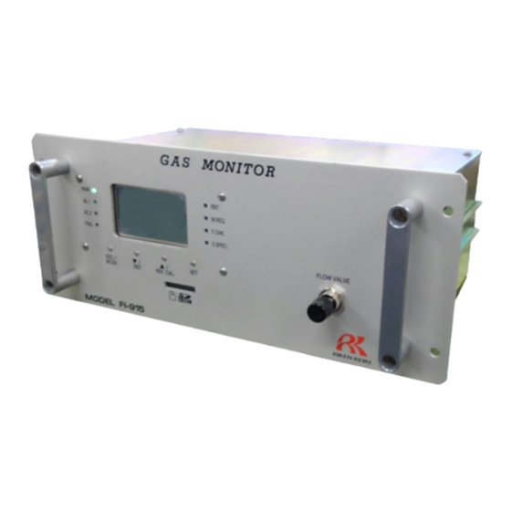
- Page 1 PT6E-0281 Optical Interferometric Gas Monitor FI-915 Operating Manual...
- Page 2 Thank you for choosing our optical interferometric gas concentration reading adjustment meter FI-915. This manual describes how to use FI-915. Not only the first-time users but also the users who have already used FI-915 must read and understand the operating manual before using FI-915.
-
Page 3: Table Of Contents
7-5. How to Replace Pump ........................58 7-6. How to Replace Fuse ........................59 8 Storage, Relocation and Disposal ......................... 60 8-1. Procedures to Store FI-915 or Leave It for a Long Time ..............60 8-2. Disposal of Products .......................... 61 9 Troubleshooting ............................. 62 9-1. - Page 4 11 Definition of Terms ............................73 - 4 -...
-
Page 5: Important Notices On Safety
FI-915 is designed to draw gases under the atmospheric pressure. If excessive pressure is applied to the gas inlet (GAS IN) and outlet (GAS OUT) of FI-915, measured gases may leak out from its inside and may cause dangerous conditions. Be sure that excessive pressure is not applied to FI-915 while used. -
Page 6: Precautions
FI-915 cannot be measured. Do not use FI-915 near a device that significantly disturbs the waveform of power supply such as electric welder. Also, do not use a power supply of the same system as a device that significantly disturbs the waveform of power supply. -
Page 7: Product Components
In addition, it has a reference calibration function that automatically performs sensor output adjustment using a reference gas (for FI-915, a zero gas such as fresh air) as a reference for concentration measurement, allowing more stable operations. -
Page 9: Accessories
2 Product Components 2-3. Accessories 2-3. Accessories 2-3-1. Standard Accessories ・ Main unit operating manual ・ MC (ST) filter (GAS IN dust filter) ・ Cylindrical filter CF-8369 (REF IN dust filter) 2-3-2. Optional Accessories SD card (2 GB) Fuse 2-3-3. Maintenance Parts ・... -
Page 11: Block Diagram
2 Product Components 2-5. Block diagram 2-5. Block diagram Absolute pressure sensor Activated Carbon filter Solenoid Pulsation prevention buffer valve Needle Pump valve Flow sensor - 11 -... -
Page 12: How To Install
3 How to Install 3-1. Precautions on Installation Site How to Install 3-1. Precautions on Installation Site Do not install FI-915 in any of the following locations. (1) Place where FI-915 is exposed to water, oil, Place with vibrations chemicals, etc. -
Page 14: How To Install Product And Precautions
Do not drop or give strong shock to FI-915 during installation. Otherwise, the device may be damaged. If FI-915 is to be fixed on a rack, etc., install it properly on a rack that can hold its weight. When performing construction work, prevent dust, etc., from entering the inside of FI-915. -
Page 15: How To Connect Wire
3 How to Install 3-3. How to Connect Wire 3-3. How to Connect Wire 3-3-1. Descriptions of External Terminal Plate And How to Connect Wire <Details of the terminal plate> (11) 100 - 240 VAC ± 10% 50/60 Hz (12) This is not used. -
Page 16: Precautions On Electrical Work
(A restart may be required to recover from the momentary blackout for 50 msec or more.) To ensure continuous operation and activation, install a UPS outside FI-915. (2) Do not make the power supply line in parallel with another high-voltage/high-current line. -
Page 17: Protective Grounding
"b" contact. 3-3-3. Protective grounding For stable operation of FI-915 and safety, it must be connected to a grounding terminal. The grounding wire should be thick and short as much as possible to minimize grounding resistance. Use the EARTH terminal (terminal 3) of the external terminal plate to ground FI-915. -
Page 19: How To Tube
(8) For safety, to provide a flame arrestor for line, install it into each line of the GAS IN and GAS OUT. CAUTION FI-915 requires appropriate tubing works (selection of materials and other works) depending on types of sample gas and installation conditions. For questions about tubing works, please contact the distributor . -
Page 26: How To Operate In Check Mode
5 How to Operate in Check Mode How to Operate in Check Mode "Check mode" is mode to display/check operating states of the sensor, setting conditions of the product, etc., while continuing measurement. In this mode, measurement is not stopped and the measurement result is output to output to the 4-20mA gas concentration output signal. -
Page 27: Check Mode Menu Items
5 How to Operate in Check Mode 5-1. Check Mode Menu Items 5-1. Check Mode Menu Items The following table shows menu items selectable in check mode. The description for each item is provided on the subsequent pages. Displays the state of the Displays the state of the The 4 to 20 mA signal Displays the pressure... -
Page 28: Each Item And Details
5 How to Operate in Check Mode 5-2. Each Item and Details 5-2. Each Item and Details In the check mode menu screen, select an item to be checked using the ▲▼ buttons and press the SET button to display the detailed information of the item. This section describes detailed information displayed for each item. - Page 29 5 How to Operate in Check Mode 5-2. Each Item and Details Items displayed in the optical sensor check screen and their details are as follows. Displays the program Displays the sum value Displays the revision Displays the number. of the program. number of the program.
- Page 30 5 How to Operate in Check Mode 5-2. Each Item and Details C.02.-- Check of State of Main Controller 'MAIN CONTROLLER' Displays program information of the main controller, the result of the self-diagnostic performed inside, etc. In the "MAIN CONTROLLER" menu screen, press the SET button to display the check screen. Use the ▲▼...
- Page 31 5 How to Operate in Check Mode 5-2. Each Item and Details C.03.-- Check of State of 4 to 20 mA Setting '4-20mA PARAM.' Displays the condition, setting, etc., of the 4 to 20 mA signal. In the "4-20mA PARAM." menu screen, press the SET button to display the check screen. Use the ▲▼...
- Page 32 Items displayed in the pressure sensor output check screen and their details are as follows. Displays the output of This is not used on Displays the output of the fine pressure FI-915. the absolute pressure difference sensor that sensor used for detects the flow rate of pressure correction.
- Page 33 5 How to Operate in Check Mode 5-2. Each Item and Details C.05.-- Check of Output of Temperature Sensors 'TEMP. SENSOR' Displays the output of the temperature sensors embedded in the LCD display and the sensor unit. In the "TEMP. SENSOR" menu screen, press the SET button to display the check screen. Use the ▲▼...
- Page 34 C.09.-- Check of Output of Self-diagnostic 'DIAG. ACTION (C)' Displays detailed operation settings of the LCD display and F.CHK. lamp (orange) for each condition for when FI-915 enters the "FUNCTION CHECK" state. Since this function is intended to be operated by our service engineer, its description is omitted.
- Page 35 The trace display is a function that alternately displays the normal measurement screen and the screen of an abnormal state that occurred in the past to inform the customer about the past event when the product recovers from some abnormal state to the normal state. FI-915 does not use this function.
- Page 36 This menu item is for resetting the trace display state of the LCD display and the self-latching state of the contact. Since FI-915 does not use these functions, there is no need to use this menu usually. In the menu screen, press the SET button to display the caution screen stating that it will reset the latching state of the display screen and contact.
-
Page 37: How To Operate In Setup Mode
6 How to Operate in Setup Mode How to Operate in Setup Mode "Setup mode" is mode to change the measured gas, set the condition of the 4 to 20 mA signal and set the SD card operation, etc. When this mode is entered, measurement is stopped, the "FUNCTION CHECK" state is entered and the 4 to 20 mA signal is fixed to the previous value. -
Page 38: Items In Setup Mode
6 How to Operate in Setup Mode 6-1. Items in Setup Mode 6-1. Items in Setup Mode The following table shows items that are displayed in the setup mode menu screen. The description for each item is provided on the subsequent pages. Selects the measured Sets up the 4 to 20 mA Adjusts the 4 to 20 mA... - Page 41 6 How to Operate in Setup Mode 6-2. Each Item And Details S.03.-- 4 to 20 mA Signal Adjustment '4-20mA ADJ.' The 4 to 20 mA gas concentration output signal. In the "4-20mA ADJ." menu screen, press the SET button. The "caution screen" will appear stating that the 4 to 20 mA signal will be changed. Press the ▲...
- Page 42 6 How to Operate in Setup Mode 6-2. Each Item And Details S. 04.-- 4 to 20 mA Signal Test '4-20mA TEST' Adjusts any test signal of the 4 to 20 mA output signal. In the "4-20mA TEST" menu screen, press the SET button.
- Page 43 6 How to Operate in Setup Mode 6-2. Each Item And Details S.05.-- Setup of Concentration Alarm Function 'ALARM SETUP' Set the concentration alarm function. In the "Alarm Setup" menu screen, press the SET button to display preset alarm function. After that, press the SET button. The setting contents will start blinking. Use the ▲▼...
- Page 44 6 How to Operate in Setup Mode 6-2. Each Item And Details S.06.-- Alarm Test 'ALARM TEST' Test the concentration alarm function. In the "ALARM TEST" menu screen, press the SET button to test concentration the alarm function. The "caution screen" will appear stating that the 4 to 20 mA signal will be changed and the alarm contact will be activated.
- Page 45 S.08.-- Contact Operation Check 'CONTACT TEST' Outputs a test signal of a usual/unusual state to test the operation of the contact used in FI-915. Since this function is intended to be operated by our service engineer, its description is omitted.
- Page 46 6 How to Operate in Setup Mode 6-2. Each Item And Details S.09.-- Reference Calibration 'REF. CAL' Performs the reference calibration. In the "REF. CAL" menu screen, press the SET button to display the "REF. CAL" execution standby screen. Press the SET button again to perform the reference calibration.
- Page 47 6 How to Operate in Setup Mode 6-2. Each Item And Details S.11.-- Span Adjustment 'SPAN SETUP' Performs the span adjustment of the measurement result. Since this operation is intended to be performed by our service engineer, the description of how to operate it is omitted. S.12.-- Suppression Adjustment 'SUPPRESS' Sets up the upper limit and lower limit for display of the measurement result.
- Page 48 S.17.-- Self-diagnostic Operation (at FUNCTION CHECK) 'DIAG. ACTION (C)' Sets up detailed operations of the LCD display and LED lamp for each condition for when FI-915 enters the "FUNCTION CHECK" state. Since this function is intended to be operated by our service engineer, its description is omitted.
- Page 49 6 How to Operate in Setup Mode 6-2. Each Item And Details S.19.-- Setup of RS-485 Communication 'RS-485/MODBUS' Change the RS-485 (MODBUS) communication settings. In the menu screen, press the SET key to display the setting value check screen and display the current settings of communication conditions. Use the ▲▼...
- Page 50 6 How to Operate in Setup Mode 6-2. Each Item And Details PARITY BIT: NONE, IGNORE, EVEN, ODD SEND WAIT 1 :8 to 127 characters(fixed value) SEND WAIT 2 :8 to 127 characters(random value) Displays all message receipt counters. Displays the CRC error counter. Displays the exception error counter.
- Page 51 Select OK and press the Set button to clear all counter values. Initializes the address map. CAUTION If the address map is initialized, FI-915 might not communicate properly Since this function is intended to be operated by our service engineer, do not initialize the address map.
- Page 52 6 How to Operate in Setup Mode 6-2. Each Item And Details S.20.-- SD Card Operation 'SD CARD' In the "SD CARD" menu screen, press the SET button to display the miscellaneous operation items. Use the ▲▼ buttons to select an operation item to be executed, and then press the SET button to display each execution screen.
- Page 53 "operational status" and "self-diagnostic result" recorded in FI-915 will be exported to the SD card. Press the ▲ button repeatedly to display all the texts of the "caution screen" and read them, and then press the SET button to export to the SD card (it takes 1 to 3 minutes).
- Page 55 6 How to Operate in Setup Mode 6-2. Each Item And Details S.21.-- Setup of Automatic Reference Calibration 'AUTO REF. CAL SET' The automatic reference calibration is a function to perform the reference calibration at a specific time interval automatically using a built-in timer of the product. Since this function is intended to be operated by our service engineer, its detailed description is omitted.
-
Page 63: Troubleshooting
9 Troubleshooting 9-1. FAILURE An abnormal temperature When no abnormality is recognized in the has been detected on the installation environment, main controller the main controller may malfunction. - 63 -... - Page 74 Manual Log Rev. Revision Issue date First issue 2018/7/19 2-5. Block diagram updated 2018/10/3 - 74 -...
Need help?
Do you have a question about the FI-915 and is the answer not in the manual?
Questions and answers