Advertisement
Quick Links
All manuals and user guides at all-guides.com
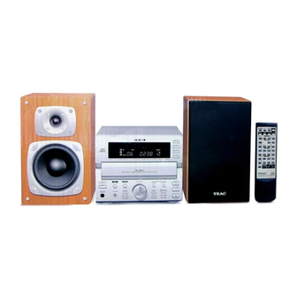
MC-D90
CD/TUNER/AMPLIFIER
NOTES
PC boards shown are viewed from parts side.
The parts with no reference number or parts number in the
exploded views are not supplied.
As regards the resistors and capacitors, refer to the circuit
diagrams contained in this manual.
Parts marked with this sigh are critical components.
They must be replaced with identical components - refer to
the appropriate parts list and ensure exact replacement.
Parts of [
] mark can be used only with the version
designated.
[J] : JAPAN
[US] : U.S.A.
[C] : CANADA
[E] : EUROPE [UK] : U.K.
[GE] : GENERAL EXPORT
9A08312000
Advertisement

Related Manuals for Teac MC-D90


Summary of Contents for Teac MC-D90
- Page 1 All manuals and user guides at all-guides.com MC-D90 CD/TUNER/AMPLIFIER NOTES PC boards shown are viewed from parts side. The parts with no reference number or parts number in the exploded views are not supplied. As regards the resistors and capacitors, refer to the circuit diagrams contained in this manual.
-
Page 2: Table Of Contents
All manuals and user guides at all-guides.com CONTENTS SPECIFICATIONS................. . 2 IC PIN FUNCTION . - Page 3 All manuals and user guides at all-guides.com IC36 PIN FUNCTION (IC : BVITMP87PM78F)(AMP) PIN No. NAME DESCRIPTION POWER SUPPLY (+5V) 1, 25 BUS for CD CLOCK HREQ BUS for CD CHIP ENABLE SLQCLK RESET for CD SLQIN MUTE for CD SINGLE SLQOUT DATA EUROPE VERSION RDS DATA CONTROL PORT...
- Page 4 All manuals and user guides at all-guides.com IC 66 PIN FUNCTION (IC : BVITMP87PM78F)(CD) PIN No. NAME DESCRIPTION POWER SUPPLY (+5V) 1, 25 BUS for CD DATA BUS 0 BUS for CD DATA BUS 1 BUS for CD DATA BUS 2 BUS for CD DATA BUS 3 BUS for CD CLOCK...
- Page 5 All manuals and user guides at all-guides.com PIN ASSIGNMENTS (TOP VIEW) PIN BLOCK DIAGRAM SERVICE MANUAL...
- Page 6 All manuals and user guides at all-guides.com IC11 (TUNER) LA1836M BLOCK DIAGRAM TDA7318D IC23(INPUT) LC4966 SERVICE MANUAL...
- Page 7 All manuals and user guides at all-guides.com ALIGNMENT INSTRUCTIONS EQUIPMENT NEEDED: AM Signal Generator FM Signal Generator Oscilloscope VTVM(AC, DC) Test loop antenna (AW Adjustment) Dummy antenna (FM Adjustment) Stereo signal modulator Frequency counter Distortion analyser IMPORTANT 1. Check power-source voltage. 2.
-
Page 8: Measurements And Adjustments
All manuals and user guides at all-guides.com MEASUREMENTS AND ADJUSTMENTS 1. FM, AM TRACKING VOLTAGE ADJUSTMENTS (FM, AM) DC VOLTMETER ......CONNECT TO TEST POINT TP1 and GND Band Frequency Adjust for Adjustment 87.50MHz 1.5V 530KHz T404 2. AM RF ADJUSTMENT Signal Generator ...... - Page 9 All manuals and user guides at all-guides.com 4. FM MONO DISTORTION ADJUSTMENT DC VOLT METER ......Connect to TP1(-), TP2(+) Through the choke coll (100 H) Signal Generator......Connect to FM ANT Jack (FM IN) through the dummy. Distortion Meter ......Connect to the output. Frequency Adjust for Adjustment...
-
Page 10: Block Diagram
All manuals and user guides at all-guides.com TA2092N (POWER DRIVER) PIN No. NAME DESCRIPTION Power GND Connected to substrate. PW GND pin are connected inside. Inverted output for CH1 OUT (-) 1 Supply terminal of output stage for CH1 Supply terminal of output stage are not connected to other channel terminal. Non-inverted output for CH1 OUT (+) 1 Input for CH1. - Page 11 All manuals and user guides at all-guides.com TA2109F (RF/DIGITAL SERVOR) PIN No. NAME DESCRIPTION REMARK Power supply input terminal Main beam I-V amp input terminal Connected to pin diode A,C Main beam I-V amp input terminal Connected to pin diode B,D Sub beam I-V amp input termianl Connected to pin diode F Sub beam I-V amp input termianl...
- Page 12 All manuals and user guides at all-guides.com SERVICE MANUAL...
- Page 13 All manuals and user guides at all-guides.com SERVICE MANUAL...
- Page 14 All manuals and user guides at all-guides.com SERVICE MANUAL...
- Page 15 All manuals and user guides at all-guides.com SERVICE MANUAL...
- Page 16 All manuals and user guides at all-guides.com SERVICE MANUAL...
- Page 17 All manuals and user guides at all-guides.com SERVICE MANUAL...
- Page 18 All manuals and user guides at all-guides.com...
- Page 19 All manuals and user guides at all-guides.com...
-
Page 20: Schematic Diagram
All manuals and user guides at all-guides.com SCHEMATIC DIAGRAM... - Page 21 All manuals and user guides at all-guides.com...
-
Page 22: Printed Circuit Boards
All manuals and user guides at all-guides.com PRINTED CIRCUIT BOARDS... - Page 23 All manuals and user guides at all-guides.com...
- Page 24 All manuals and user guides at all-guides.com SERVICE MANUAL...
- Page 25 INCLUDED ACCESSORIES REF. NO. PARTS NO. DESCRIPTION REMARKS 9A08561000 SPEAKER ASS'Y LS-H90A 9A01397000 ANTENNA TERMINAL T-60 KSA267 9A07871200 REMOCON TRANSMITTER ASS'Y CARTCR-H100TCCC 9A08523100 OWNER'S MNL,T/C MC-D90 CQX1A614Z 9A08046100 ADAPTOR,75-300 (NTSC) KLR1T201 9A08561100 AM LOOP ANTENNA ASS'Y KSA3A012Z SERVICE MANUAL SERVICE MANUAL...
- Page 26 All manuals and user guides at all-guides.com EXPLODED VIEW MC-D90TC ...
-
Page 27: Exploded View
2- 4 9A08562500 ORNAMENT, DOOR CGR1A203M7ZK101 2- 5 9A08562600 WINDOW CGU1A240 2- 6 9A08562300 ORNAMENT, FRONT CGK1A057ZC25 2- 7 9A08127900 BADGE, TEAC KGB1A080Z 2- 8 9A07889500 CUSHION, FOOT KHG1A165 2- 9 9A07872900 FOOT CKL1A059M9K63 2-10 9A08562800 PANEL, FRONT CGW1A289M7ZK101 2-11... - Page 28 All manuals and user guides at all-guides.com SERVICE MANUAL...
- Page 29 All manuals and user guides at all-guides.com MAIN PCB ASS’Y REF. NO. PARTS NO. DESCRIPTION REMARKS 9A08215500 MAIN PCB ASS’Y COP11318B 9A08217300 MAIN PCB CUP11318Y C 124 9A07886400 CAP, STYROLE HCQS1H471JZ C 127 9A01405900 C, VARIABLE 20PF A020S12 KCRA020S12 C 129 9A07882400 CAP, ELECT 100UF/16V HCEA1CH101T...
- Page 30 All manuals and user guides at all-guides.com MAIN PCB ASS’Y REF. NO. PARTS NO. DESCRIPTION REMARKS JK21 9A07872700 TERMINAL, IN/OUT CJJ4R012Z JK22 9A07889600 JACK , PIN BOARD KJJ4R018Z JW21 9A06867500 WIRE , ASS’Y KWZAH300JW74 JW51 9A07295100 WIRE ASSS’Y KWZAAV1100W801 L 130 9A07886600 COIL , AXAIL 10UH HLQ02C100KT...
- Page 31 All manuals and user guides at all-guides.com MAIN PCB ASS’Y REF. NO. PARTS NO. DESCRIPTION REMARKS T 901 9A07873400 TRANS, POWER(MAIN) CLT5P037ZU TF01 9A08215300 PACK , FRONT END CNVKSTF401VA3 TW91 9A06674400 WAFER, 7.92MM (YUNHO) KJP02KA060ZY VR11 9A05940500 R, SEMI FIXED EVNDJAA03B53 BVN1PA502B01T VR12 9A08040700...
- Page 32 All manuals and user guides at all-guides.com CD PCB ASS’Y REF. NO. PARTS NO. DESCRIPTION REMARKS 9A08563300 CD PCB ASS’Y COP11381B 9A08564000 CD PCB CUP11381Z BN66 9A08222000 WIRE ASS’Y KWDB015150EW BN67 9A08222200 WIRE ASS’Y KWZCR130BN67 CN61 9A08220300 WAFER , CARD CABLE (STRAI) KJP16GA117ZG CN62 9A08220400...
Need help?
Do you have a question about the MC-D90 and is the answer not in the manual?
Questions and answers