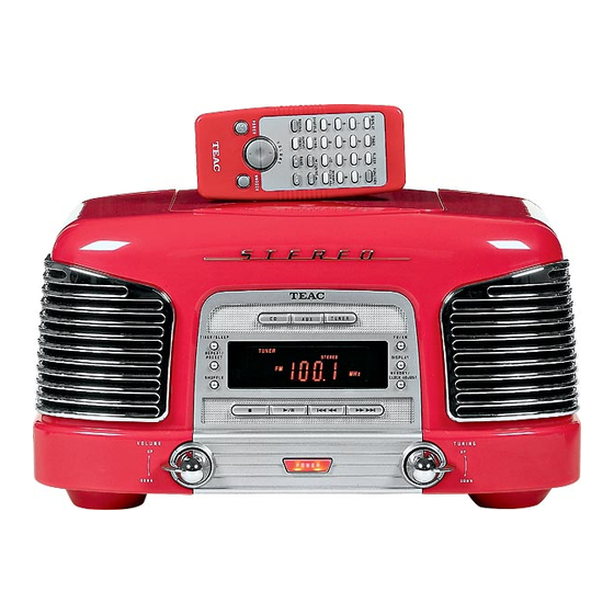
Teac SL-D90 Service Manual
Am/fm stereo digital
radio with cd player
Hide thumbs
Also See for SL-D90:
- Owner's manual (24 pages) ,
- Service manual (35 pages) ,
- Service manual (27 pages)
Table of Contents
Advertisement
PC board shown are viewed from parts side.
The parts with no reference number or no parts number
in the exploded views are not supplied.
As regards the resistors and capacitors, refer to the
circuit diagrams contained in this manual.
!
Parts marked with this sign are safety critical
components. they must be replaced with identical
components - refer to the appropriate parts list and
ensure exact replacement.
Parts of [ ] mark can be used only with the version designated.
[UL/CSA]: T/C
[ME/UNI]: EX/T [JIS]: DM [IT]: EUR
[HK]: UK/HKG
SL-D90
AM/FM STEREO DIGITAL
RADIO WITH CD PLAYER
3 ADJUSTMENT AND CHECKS
4 EXPLODED VIEW AND PARTS LIST
2
3
4
7
13
23
25
Advertisement
Table of Contents

Related Manuals for Teac SL-D90


Summary of Contents for Teac SL-D90
- Page 1 SL-D90 AM/FM STEREO DIGITAL RADIO WITH CD PLAYER 1 SAFETY INFORMATION PC board shown are viewed from parts side. The parts with no reference number or no parts number 2 SPECIFICATIONS in the exploded views are not supplied. 3 ADJUSTMENT AND CHECKS...
-
Page 2: Safety Information
SL-D90 1 SAFETY INFORMATION SAFETY INFORMATION This product has been designed and manufactured according to FDA regulations " title 21, CFR, chapter 1,subchapter J,based on the Radiation Control for Health and Safety Act of 1968" and is classified as class 1 laser product. There is not hazardous invisible laser radiation during operation because invisible laser radiation emitted inside of this product is completely confined in the protective housings. -
Page 3: Specifications
SL-D90 2 SPECIFICATIONS TUNER Section 87.5MHz to 108.00 MHz Frequency Range (FM): Frequency Range (AM): 520kHz to 1710 kHz CD PLAYER Section Frequency Response: 20 Hz to 20 kHz (+/- 1dB) Unmeasurable Wow and Flutter: SPEAKER SYSTEM Section Type: 1-way Impedance: 8 ohms (L &... -
Page 4: Tuner Section
SL-D90 3 ADJUSTMENTS AND CHECKS 3-1 TUNER SECTION Use a screwdriver with a plastic or ceramic grip for all adjustment. 3-1-1 AM adjustment 1. Set the function switch to the TUNER position. 2. Set the BAND switch to the AM position. - Page 5 SL-D90 3-2-2 AM Tuner SIGNAL GENERATOR SETTING TUNER MEASURING ADJUSTMENTS ITEM SETTING Audio Modulation Frequency Output POINTS, RESULT 1710KHz 8.0V 1. VOLTAGE adjustment 530 KHz Check 1.5V Maximum 2. IFT 1KHz 610KHz 76 dBuV 610KHz output level adjustment Maximum AM ant coil 3.
- Page 6 SL-D90 3-2-4 FM Tuner SIGNAL GENERATOR SETTING TUNER MEASURING ADJUSTMENTS ITEM Audio SETTING Modulation Frequency Output POINTS, RESULT 106.1MHz Check 5.5-5.9V 1. VOLTAGE adjustment Check 90.1MHz 1.2-1.6V Maximum 2. IFT 22.5KHz 90.1MHz 25 dBuV 90.1MHz 1KHz output level adjustment FM signal generator...
- Page 7 SL-D90 4 EXPLODED VIEWS AND PARTS LIST EXPLODED VIEW - 1...
- Page 8 SL-D90 EXPLODED VIEW-1 REF. NO PARTS NO. DESCRIPTION REMARK CD PCB ASSY 100-SD902030 011-SD900300 TUNER PCB SHIELD PLATE 011-SD900200 HEAT SINK BRACKET 100-SD902010 MAIN PCB ASSY 011-SD900100 CD PCB SHIELD PLATE TUNER PCB ASSY 100-SD902040 010-SD900000 SPEAKER BOX ADIABATIC SHEET...
- Page 9 SL-D90 EXPLODED VIEW-1 REF. NO DESCRIPTION REMARK PARTS NO. 1-26 036-00000001 CLOSE END CONNECTOR 041-00000004 WIRE CLAMPER W/TUBE 1-27 1-28 100-SD902070 HEAD PHONE JACK ASSY 1-29 010-SD900600 CORD STOP 1-30 100-SD902050 AUX PCB ASSY 1-31 004-SD900700 BASE KNOB 044-SLD90040 1-32...
- Page 10 SL-D90 EXPLODED VIEW - 2...
- Page 11 SL-D90 EXPLODED VIEW-2 REMARK REF. NO DESCRIPTION PARTS NO. 007-SD900100 LCD DISPLAY WINDOW 004-SD900100 VOLUME KNOB 004-SD900200 TUNER KNOB 001-SD900300 CONTROL PANEL 012-02120612 PVC WASHER 009-28000000 TUNER/VOLUME SW. LEVER 031-28000010 VOLUME SPRING 010-SD900700 VOLUME SPRING COVER 010-SD900800 TUNER SPRING COVER...
- Page 12 SL-D90 EXPLODED VIEW-2 REMARK REF. NO PARTS NO. DESCRIPTION 2-34 001-SD900000 FRONT PANEL-RED (T/C,EX/T,EUR,UK/HKG) 001-SD900001 FRONT PANEL-WHITE (T/C,EX/T,EUR,UK/HKG) 001-SD900002 FRONT PANEL-JADE (T/C,EX/T,EUR,UK/HKG) 001-SD900003 FRONT PANEL-BLACK (T/C,EX/T,EUR,UK/HKG) 001-SD900005 FRONT PANEL-RED (DM) 001-SD900006 FRONT PANEL-WHITE (DM) 001-SD900007 FRONT PANEL-JADE (DM) 001-SD900008 FRONT PANEL-BLACK (DM)
-
Page 13: Pc Boards And Parts List
SL-D90 5 PC BOARDS AND PARTS LIST MAIN PCB ASSY REMARK PARTS NO. REF. NO DESCRIPTION 100-SD902010 MAIN PCB ASSY 062-SLD90000 MAIN PCB C64,67,68 072-30100251 CE, 25V 1000UF 072-30220251 CE, 25V 2200UF 072-30470251 CE, 25V 4700UF 082-10440100 CONNECTOR 4P P=2.5MM CONNECTOR 3PIN P=2.5MM... - Page 14 CD IN C140 M G L R R116 R111 R101 SPEAKER-R WOOFER SPEAKER-L R118 R113 R117 R114 R115 R103 R112 R122 AUX INPUT IC12 R100 R102 R135 R134 062-SLD90000 CN19 REV.02 94-V0 E193177 SL-D90 MAIN PCB 2002.09.06 G.F.KOU FUSE01 CN15 T2AL/250V...
- Page 15 SL-D90 CD PCB ASSY PARTS NO. DESCRIPTION REMARK REF. NO 100-SD902030 CD PCB ASSY 062-SLD90002 CD PCB C230 072-30220101 CE, 10V 2200UF 082-21250100 CONNECTOR 12PIN P=1.25MM CN12 082-23050100 CONNECTOR 30PIN P=1.25MM CN16 082-20400100 CONNECTOR 4PIN P=2MM 082-10600100 CONNECTOR 6PIN P=2MM...
- Page 16 SL-D90 CD PCB C240 IC10 TA2092N C238 R207 C241 C246 C209 C242 C243 C203 R231 R249 C244 R201 R255 C258 C201 R232 C237 C247 R244 C208 R247 J032 C251 R245 R248 C255 C217 C222 R246 R242 C207 C219 C221 R240...
- Page 17 SL-D90 TUNER PCB ASSY PARTS NO. DESCRIPTION REMARK REF. NO 100-SD902040 TUNER PCB ASSY 062-SLD90003 TUNER PCB 056-10080001 FERRITER BAR D10x80MM CF1,CF2 AM FILTER L10.7MA5-A 081-31070001 081-04500000 FM FILTER SFU450B CN10 082-10600100 CONNECTOR 6PIN P=2MM D16-21 077-00414801 DIODE IN4148 F001...
-
Page 18: Tuner Pcb
SL-D90 TUNER PCB C106 R181 R151 R179 C117 J107 J106 J112 C103 J109 R150 C118 J108 C114 R154 IF-M C135 C133 R170 C111 C136 C144 CN10 C134 J114 R166 J104 R167 R168 J100 J101 C116 R148 R165 R183 R161 R160... - Page 19 SL-D90 CONTROL PCB ASSY PARTS NO. DESCRIPTION REMARK REF. NO 100-SD902020 CONTROL PCB ASSY CONTROL PCB 062-SLD90001 LCD1 080-SLD90021 LCD DISPLAY LED 3MM-ORANGE LED01,03 094-03020301 Q301-304 076-00C94500 TR-2SC945 SW01,04-10,012, TACH SW H=5MM 063-0GP28020 SW014-018 SW02,03,011,013 TACH SW SKHHALM 063-D2800020...
-
Page 20: Display Lcd
SL-D90 CONTROL PCB SL-D90 CONTROL PCB 062-SLD90001 SW04 SW06 SW05 2002-6-7 TUNER DISPLAY LCD R328 LCD1 SW09 SW018 R323 FM/AM SLEEP SW014 SW015 REPEAT DISPLAY CW12 SW016 SW017 J308 RANDOM CL0CK J318 J319 J305 SW08 SW07 SW012 SW010 STOP R313... - Page 21 SL-D90 SNOOZE PCB ASSY REF. NO REF. NO PARTS NO. PARTS NO. DESCRIPTION REMARK 100-SD902080 SNOOZE PCB ASSY SNOOZE PCB TACH SW H=4.3MM SW019,021 063-SLD90000 TACH SW H=5MM SW020 063-SLD90001 AUX PCB ASSY REF. NO PARTS NO. DESCRIPTION REMARK 100-SD902050...
- Page 22 SL-D90 SNOOZE PCB REV:00 2002.6.1. SL-D90 SNOOZE PCB 94-HB REV:00 CW14A SNOOZE SNOOZE 2002.6.1. SNOOZE SW021 SW019 SW020 AUX PCB IN G OUT R G L AUX JACK PCB 94-HB REV:00 JK02 JK03 CD SWITCH PCB RESET CD SW. PCB...
- Page 23 SL-D90 6 WIRING DIAGRAM TO SPEAKER-P TO SPEAKER-L TO WOOFER TO PHONE JACK CW1 MAIN PCB CN11 TO TUNER PCB CW1 1 TO CD PCB CW6 TO AUX JACK PCB CW7 CN19 TO TRANSFORMER CN15 TO CD PCB CN5...
- Page 24 SL-D90 TO CD DECK MOTOR CD PCB CN18 CW10 TO CD PICK UP TO TUNER PCB CN10 TO CD SWITCH PCB CW16 TO CONTROL PCB CW12...
- Page 25 SL-D90 7 INCLUDED ACCESSORIES INCLUDED ACCESSORIES PARTS NO. DESCRIPTION REF. NO REMARK 047-D2831000 GUARANTEE SHEET 046-SLD90000 INSTRUCTION BOOK - E/F (T/C) 046-SLD90010 INSTRUCTION BOOK - S/P (EX/T) 046-SLD90020 INSTRUCTION BOOK - J (DM) 046-SLD90030 INSTRUCTION BOOK - I/S (EUR) 046-SLD90040...
- Page 26 TEAC NEDERLAND BV Oeverkruid 15,NL-4941 W Raamsdonksveer, Nederland Phone:0162-510210 TEAC BELGIUM NV/SA. c/o TEAC NEDERLAND BV, Oeverkruid 15, NL-4941 W Raamsdonksveer, Nederland Phone:+31-162-510860 TEAC ITALIANA S.p.A. Via C, Cantu 11, 20092 Cinisello Balsamo, Milano, Italy Phone:02-66010550 TEAC AUSTRALIA PTY., LTD.
- Page 27 R101 R102 C76 10UF 100K 2200UF AC INPUT: R109 R110 100UF 10UF D7 1N4002 D8 1N4002 100K 100K 100K 120V/60HZ FUSE01 T2AL/250V 2SC945 C84 103 R122 10K C8 223 C7 223 47UF SL-D90 AM/FM STEREO DIGITAL RADIO WITH CD PLAYER...
- Page 28 VOL-CE 100K RESET VL-CLK VL-DATA DOOR SW FUNC A FUNC B SW022 C254 OPEN/CLOSE R254 820 R253 15K SW021 C226 47UF SW020 CW14 CW14 SW019 KEY-AD3 RESET/DOOE SW PCB SNOOZE SW PCB SL-D90 AM/FM STEREO DIGITAL RADIO WITH CD PLAYER...
- Page 29 DISPLAY DOWN D01 1N4148 POWER COM4 COM3 COM2 COM1 1 2 3 4 5 6 7 8 9 10 1112 13 14 15 16 1718 19 20 21 22 SL-D90 REPEAT SNOOZE CD TUNER SHUFFLE MUTING SLEEP MEMORY INTRO STEREO...
- Page 30 (3) Detach the Rear Case from the Front Case. (4) Remove screws from the Main PCB Assy and the Heatsink. * 5 indicated by Red. * 1 indicated by Red from the Heatsink.
- Page 31 (5) The Main PCB A is detached and lying down by disconnecting the following cables. *Disconnect all the cables with connector. Power cables from the Power X’mer 3 at Left side From Headphone 3 from Speakers...
- Page 32 FFC from CD PCB A *Other cables are from TUNER PCB A and AUX PCB A (6) Disconnect cables from CD Drive unit and CD PCB A *This connector is inside of the Main body at right-hand side. The Pickup FFC can be extracted at one of both end, red or blue...
- Page 33 (7) CD Drive unit can be detached from the Main body by fulfilling above steps. Extract this section as the CD Drive unit is mounted at its backside (8) Set the section upside-down to remove 4 mounting screws. (9) The CD Drive unit = Traverse unit is now replaced with detaching the Cover.
- Page 34 (10) The Power X’mer can be replaced after removal of CD Drive unit by the following steps. (11) 4 metal brackets have to be detached. *Insert (-) driver to release a latch of the bracket inside and extract it. *Treat same manner to detach another 3 metal brackets.
- Page 35 (12) Extract the Front Case from the Main body to view the mounting screw of the Power X’mer. * As there is a headphone unit at right-hand side, mind to reserve some space there. (13) The Power X’mer is now replaced by removing 2 screws.
Need help?
Do you have a question about the SL-D90 and is the answer not in the manual?
Questions and answers
Benutzerhandbuch in Deutsch
The provided context does not mention a user manual in German for the Teac SL-D90.
This answer is automatically generated