Table of Contents
Advertisement
Quick Links
Advertisement
Table of Contents

Related Manuals for Data Translation DT9850 Series


Summary of Contents for Data Translation DT9850 Series
- Page 1 Title Page UM-22600-M DT9850 Series User’s Manual...
- Page 2 Information furnished by Data Translation, Inc. is believed to be accurate and reliable; however, no responsibility is assumed by Data Translation, Inc. for its use; nor for any infringements of patents or other rights of third parties which may result from its use.
- Page 3 Changes or modifications to this equipment not expressly approved by Data Translation could void your authority to operate the equipment under Part 15 of the FCC Rules.
-
Page 5: Table Of Contents
Wiring Signals to the DT9850 Series Module ........ - Page 6 Contents Testing Single-Value Digital Output ..........47 Part 2: Using Your Module.
- Page 7 Contents Counter/Timers ............. . 74 Tachometers.
- Page 8 Contents...
-
Page 9: About This Manual
About this Manual The first part of this manual describes how to install and set up your DT9850 Series module and device driver, and verify that your module is working properly. The second part of this manual describes the features of the DT9850 Series modules, the capabilities of the DT9850 Series Device Driver, and how to program a DT9850 Series module using the DT-Open Layers for .NET Class Library™... -
Page 10: Conventions Used In This Manual
• Items that you select or type are shown in bold. Related Information Refer to the following documents for more information on using the DT9850 Series module: • Benefits of the Universal Serial Bus for Data Acquisition. This white paper describes why USB is an attractive alternative for data acquisition. -
Page 11: Chapter 1: Overview
Overview DT9850 Series Hardware Features .......... -
Page 12: Dt9850 Series Hardware Features
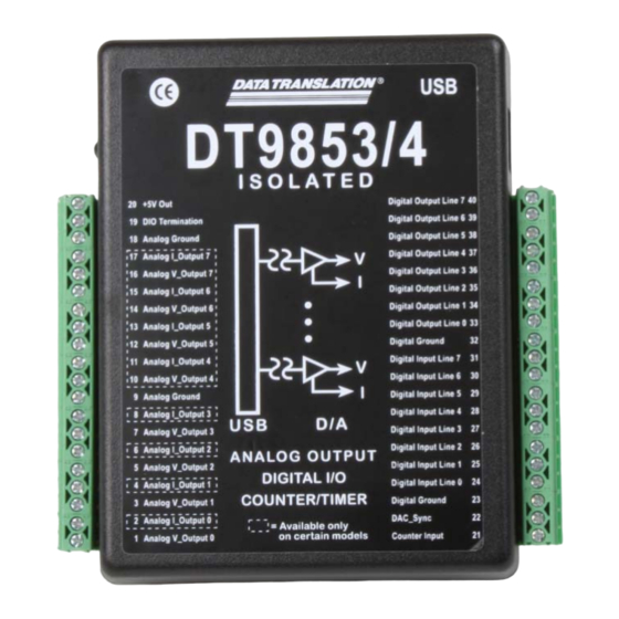
Chapter 1 DT9850 Series Hardware Features The DT9850 Series is a family of low-cost analog output and digital I/O modules for the USB (Ver. 2.0 or Ver. 1.1) bus. The DT9850 Series includes the DT9853, DT9853-M, DT9854, and DT9854-M modules. - Page 13 Overview All DT9850 Series modules share the following major features: • Analog output resolution of 16 bits • Analog output range of ±10 V or 0 to 10 V • Update analog output channels with a continuous waveform or with a single value •...
-
Page 14: Supported Software
Chapter 1 Supported Software The following software is available for use with the DT9850 Series module and is on the Data Acquisition OMNI CD: • DT9850 Series Device Driver – The device driver allows you to use a DT9850 Series module with any of the supported software packages or utilities. -
Page 15: Getting Started Procedure
Figure 2 illustrates the steps needed to get started using the DT9850 Series module. This diagram is repeated in each Getting Started chapter; the shaded area in the diagram shows you where you are in the getting started procedure. Set Up and Install the Module... - Page 16 Chapter 1...
-
Page 17: Part 1: Getting Started
Part 1: Getting Started... -
Page 19: Chapter 2: Setting Up And Installing The Module
Computer..........Configuring the DT9850 Series Device Driver... - Page 20 Appendix Set Up and Install the Module (this chapter) Wire Signals (see Chapter 3 starting on page Verify the Operation of the Module (see Chapter 4 starting on page...
-
Page 21: Unpacking
• USB cable • Data Acquisition OMNI CD-ROM If an item is missing or damaged, contact Data Translation. If you are in the United States, call the Customer Service Department at (508) 481-3700, ext. 1323. An application engineer will guide you through the appropriate steps for replacing missing or damaged items. If you are located outside the United States, call your local distributor, listed on Data Translation’s web... -
Page 22: System Requirements
Appendix System Requirements For reliable operation, ensure that your computer meets the following system requirements: • Processor: Pentium 4/M or equivalent • RAM: 1 GB • Screen Resolution: 1024 x 768 pixels • Operating System: Windows 8, Windows 7, Windows Vista (32- and 64-bit) •... -
Page 23: Attaching Modules To The Computer
Notes: Most computers have several USB ports that allow direct connection to USB devices. If your application requires more DT9850 Series modules than you have USB ports for, you can expand the number of USB devices attached to a single USB port by using expansion hubs. -
Page 24: Connecting Directly To The Usb Port
Appendix Connecting Directly to the USB Port To connect a DT9850 Series module directly to a USB port on your computer, do the following: 1. Attach one end of the USB cable to the USB port on the module. 2. Attach the other end of the USB cable to one of the USB ports on the host computer, as... -
Page 25: Connecting To An Expansion Hub
Connecting to an Expansion Hub Expansion hubs are powered by their own external power supply. The practical number of DT9850 Series modules that you can connect to a single USB port depends on the throughput you want to achieve. To connect multiple DT9850 Series modules to an expansion hub, do the following: 1. - Page 26 Note: Once you have connected your module to the host computer, power is turned on to the DT9850 Series module when your application program opens the module. The LED on the module turns green to indicate that power is turned on.
-
Page 27: Configuring The Dt9850 Series Device Driver
The Data Acquisition Control Panel dialog box appears. 4. Click the DT9850 Series module that you want to configure, and then click Advanced. 5. Click the Digital Input Mask tab to select the digital input lines that you want to enable for interrupt-on-change detection, where bit 0 corresponds to digital input line 0, bit 1 corresponds to digital input line 1, and so on. - Page 28 OK. The name is used to identify the module in all subsequent applications. 9. Repeat steps 4 to 8 for the other DT9850 Series modules that you want to configure. 10. When you are finished configuring the modules, click Close.
-
Page 29: Chapter 3: Wiring Signals
Wiring Signals Preparing to Wire Signals ............Connecting an Analog Output Signal . - Page 30 Chapter 3 Set Up and Install the Module (see Chapter 2 starting on page Wire Signals (this chapter) Verify the Operation of the Module (see Chapter 4 starting on page...
-
Page 31: Preparing To Wire Signals
• Prevent electrostatic discharge to the I/O while the DT9850 Series module is operational. Wiring Signals to the DT9850 Series Module All DT9850 Series modules provide screw terminals for easy signal connections. - Page 32 Chapter 3 Table 2: DT9853 Screw Terminal Assignments Screw Screw Terminal Signal Terminal Signal +5 V Out Digital Output, Line 7 Digital I/O Termination Select Digital Output, Line 6 Analog Ground Digital Output, Line 5 Reserved Digital Output, Line 4 Reserved Digital Output, Line 3 Reserved...
- Page 33 Wiring Signals Table 3: DT9853-M Screw Terminal Assignments Screw Screw Terminal Signal Terminal Signal +5 V Out Digital Output, Line 7 Digital I/O Termination Select Digital Output, Line 6 Analog Ground Digital Output, Line 5 Reserved Digital Output, Line 4 Reserved Digital Output, Line 3 Reserved...
- Page 34 Chapter 3 Table 4: DT9854 Screw Terminal Assignments Screw Screw Terminal Signal Terminal Signal +5 V Out Digital Output, Line 7 Digital I/O Termination Select Digital Output, Line 6 Analog Ground Digital Output, Line 5 Reserved Digital Output, Line 4 Analog V_Output 7 Digital Output, Line 3 Reserved...
- Page 35 Wiring Signals Table 5: DT9854-M Screw Terminal Assignments Screw Screw Terminal Signal Terminal Signal +5 V Out Digital Output, Line 7 Digital I/O Termination Select Digital Output, Line 6 Analog Ground Digital Output, Line 5 Analog I_Output 7 Digital Output, Line 4 Analog V_Output 7 Digital Output, Line 3 Analog I_Output 6...
-
Page 36: Connecting An Analog Output Signal
Chapter 3 Connecting an Analog Output Signal This section describes how to connect a voltage or current output signal to a DT9850 Series module. Connecting Voltage Output Signals Figure 5 shows how to connect a voltage output signal, in this case Analog V_Output 0, to a DT9850 Series module. - Page 37 Wiring Signals DT9853-M or DT9854-M Module Floating Load Analog I_Output 0 Grounded External Excitation Voltage Supply – Analog Ground Figure 6: Connecting a Grounded External Excitation Voltage Supply (Floating Load) to a Current Output Signal of a DT9853-M or DT9854-M Module Figure 7 shows an example of connecting a floating excitation voltage supply (the load is grounded) to a current output channel of the DT9853-M or DT9854-M module.
-
Page 38: Connecting Digital I/O Signals
I/O signals for pull-up; Figure 9 shows how to configure the digital I/O signals for pull-down. DT9850 Series Module +5V Out Digital I/O Termination Select Figure 8: Configuring the Digital Input Signals for Pull-Up (High Value) -
Page 39: Connecting Digital Input Signals
TTL Inputs Digital Input Port, Line 1 Digital Ground Figure 10: Connecting Digital Inputs to a DT9850 Series Module Connecting Digital Output Signals Figure 11 shows how to connect a digital output signal (line 0 of the digital output port, in this case) to a DT9850 Series module. -
Page 40: Connecting Event Counting Signals
Chapter 3 Connecting Event Counting Signals Figure 12 shows how to connect the Counter Input signal to the DT9850 Series module for an event counting application. DT9850 Series Module Digital Ground Signal Source Counter Input Events are counted on rising edges of the Counter Input signal. -
Page 41: Chapter 4: Verifying The Operation Of A Module
Verifying the Operation of a Module Running the Quick DataAcq Application......... Testing Single-Value Analog Output . - Page 42 Verify the Operation of the Module (this chapter) You can verify the operation of a DT9850 Series module using the Quick DataAcq application. Quick DataAcq lets you do the following: • Output a single value from the analog output channel •...
-
Page 43: Running The Quick Dataacq Application
For information on each of the features provided, use the online help for the Quick DataAcq application by pressing F1 from any view or selecting the Help menu. If the system has trouble finding the help file, navigate to C:\Program Files\Data Translation\Win32\ dtdataacq.hlp, where C: is the letter of your hard disk drive. -
Page 44: Testing Single-Value Analog Output
2. In the QuickDataAcq application, choose Single Analog Output from the Control menu. 3. Select the appropriate DT9850 Series module from the Board list box. 4. In the Channel list box, select analog output channel 0. -
Page 45: Testing Continuous Analog Output
2. In the QuickDataAcq application, choose Wave Generator from the Control menu. 3. Select the appropriate DT9850 Series module from the Board list box. 4. In the Waveform area, select Square to output a square wave, Sine to output a sine wave, or Triangle to output a triangle waveform. -
Page 46: Testing Single-Value Digital Input
Testing Single-Value Digital Input To verify that the board can read a single digital input value, do the following: 1. Connect a digital input to line 0 of the digital input port on the DT9850 Series module. Refer to page 39 for an example of how to connect a digital input. -
Page 47: Testing Single-Value Digital Output
Testing Single-Value Digital Output To verify that the module can output a single digital output value, do the following: 1. Connect a digital output to line 0 of the digital output port on the DT9850 Series module. Refer to page 39 for an example of how to connect a digital output. - Page 48 Chapter 4...
-
Page 49: Part 2: Using Your Module
Part 2: Using Your Module... -
Page 51: Chapter 5: Principles Of Operation
Principles of Operation Analog Output Features ............Digital I/O Features. - Page 52 Chapter 5 Figure 13 shows a block diagram of the DT9850 Series module. Serial Clock Serial Clock Voltage Output Serial Data Channels Serial Data Out Current 0 to 3 Output Processor Voltage Output Channels Current 4 to 7 Serial Output...
-
Page 53: Analog Output Features
0 V ±10 mV. Resetting the module does not clear the values in the analog output channels. Output Ranges and Gains All DT9850 Series modules support an output range of ±10 V (default) or 0 to 10 V. Specify the range for the entire subsystem using software; you cannot specify unique ranges for individual channels. -
Page 54: Output Resolution
0000 to the output corresponds to 0 mA; writing a code of FFFF to the output corresponds to 20 mA. Output Resolution All DT9850 Series modules support an analog output resolution of 16 bits. The resolution cannot be programmed in software. Output Clock (Continuous Mode Only) -
Page 55: Operation Modes
Principles of Operation Operation Modes You can perform the following analog output operations on DT9850 Series modules: • Update one analog output channel with a single value • Simultaneously update analog output channels on one module with a single value •... - Page 56 In this scheme, you must configure the trigger source for one module (called the master module) as Software. Configure the trigger source for the other DT9850 Series modules (called slave modules) as an External Positive TTL trigger. In this configuration, the DAC_Sync signal is configured as an output on the master module and as an input on the slave modules.
-
Page 57: Continuously Updating Analog Output Channels On One Module
Continuously Updating Analog Output Channels on One Module with a Waveform If you want to write a waveform to one or more analog output channels on one DT9850 Series module, use software to perform a continuously paced analog output operation. This is also known as streaming analog output data. -
Page 58: Data Transfer
• LSB is the least significant bit. • FSR is the full-scale range. For the DT9850 Series, the full-scale analog output range is 10 for the unipolar range of 0 to 10 V, or 20 for the bipolar range of ±10 V. - Page 59 Principles of Operation For example, assume that you are using a DT9853 module with a bipolar output range of ±10 V. The minus full-scale value is −10 V. If you want to output a voltage of 4.7 V, determine the code value as follows: LSB = = 0.000305 V 65536...
-
Page 60: Digital I/O Features
Interrupts The DT9850 Series modules can generate an interrupt when digital input line 0 to 6 of the digital input port changes state. This feature is useful when you want to monitor critical signals or when you want to signal the host computer to transfer data to or from the module. -
Page 61: Operation Modes
Principles of Operation Operation Modes DT9850 Series modules support the following digital I/O operation modes: • Single-value operations – Use software to specify the DIN or DOUT subsystem, the resolution (8), and the gain (1) of the subsystem. Data is then read from or written to the appropriate digital I/O lines. -
Page 62: Counter/Timer Features
Chapter 5 Counter/Timer Features DT9850 Series modules provide one 32-bit counter/timer (counter/timer subsystem 0) that accepts a counter input signal with a frequency of up to 1 MHz. The module counts the number of rising edges that occur on the counter input signal. You can count a maximum of 4,294,967,296 events before the counter rolls over to 0 and starts counting again. -
Page 63: Chapter 6: Supported Device Driver Capabilities
Supported Device Driver Capabilities Data Flow and Operation Options..........Buffering . -
Page 64: Options
The tables in this chapter summarize the features available for use with the DT-Open Layers for .NET Class Library and the DT9850 Series module. The DT-Open Layers for .NET Class Library provides properties that return support information for specified subsystem capabilities. -
Page 65: Data Flow And Operation Options
Supported Device Driver Capabilities Data Flow and Operation Options Table 8: Data Flow and Operation Options DT9850 Series DOUT TACH QUAD Single-Value Operation Support SupportsSingleValue Simultaneous Single-Value Output Operations SupportsSetSingleValues Continuous Operation Support SupportsContinuous Continuous Operation until Trigger SupportsContinuousPreTrigger Continuous Operation before & after Trigger... -
Page 66: Buffering
Chapter 6 Buffering Table 9: Buffering Options DT9850 Series DOUT TACH QUAD Buffer Support SupportsBuffering Single Buffer Wrap Mode Support SupportsWrapSingle Inprocess Buffer Flush Support SupportsInProcessFlush Triggered Scan Mode Table 10: Triggered Scan Mode Options DT9850 Series DOUT TACH QUAD... -
Page 67: Channels
Supported Device Driver Capabilities Channels Table 12: Channel Options DT9850 Series DOUT TACH QUAD Number of Channels NumberOfChannels 4 or 8 SE Support SupportsSingleEnded SE Channels MaxSingleEndedChannels 4 or 8 DI Support SupportsDifferential DI Channels MaxDifferentialChannels Maximum Channel-Gain List Depth... -
Page 68: Ranges
0 to 10 V a. The DT9850 Series modules support an output range of ±10 V and 0 to 10 V. If you are using a DT9853-M or DT9854-M module and connect a current output signal to the module, the actual current that is output depends on the code that you write, the selected voltage range, and the load that you apply to the signal. -
Page 69: Current And Resistance Support
SupportedExcitationCurrentValues a. The DT9850 Series modules support an output range of ±10 V and 0 to 10 V. If you are using a DT9853-M or DT9854-M module and connect a current output signal to the module, the actual current that is output depends on the code that you write, the selected voltage range, and the load that you apply to the signal. -
Page 70: Thermocouple, Rtd, And Thermistor Support
Chapter 6 Thermocouple, RTD, and Thermistor Support Table 17: Thermocouple, RTD, and Thermistor Support Options DT9850 Series DOUT TACH QUAD Thermocouple Support SupportsThernocouple RTD Support SupportsRTD Thermistor Support SupportsThermistor Voltage Converted to Temperature SupportsTemperatureDataInStream Supported Thermocouple Types ThermocoupleType Supports CJC Source Internally in Hardware... -
Page 71: Iepe Support
Supported Device Driver Capabilities IEPE Support Table 18: IEPE Support Options DT9850 Series DOUT TACH QUAD IEPE Support SupportsIEPE Software Programmable AC Coupling SupportsACCoupling Software Programmable DC Coupling SupportsDCCoupling Software Programmable External Excitation Current Source SupportsExternalExcitationCurrentSrc Software Programmable Internal Excitation... -
Page 72: Start Triggers
Chapter 6 Start Triggers Table 20: Start Trigger Options DT9850 Series DOUT TACH QUAD Software Trigger Support SupportsSoftwareTrigger External Positive TTL Trigger Support SupportsPosExternalTTLTrigger External Negative TTL Trigger Support SupportsNegExternalTTLTrigger External Positive TTL Trigger Support for Single-Value Operations SupportsSvPosExternalTTLTrigger External Negative TTL Trigger Support for... -
Page 73: Reference Triggers
Supported Device Driver Capabilities Reference Triggers Table 21: Reference Trigger Options DT9850 Series DOUT TACH QUAD External Positive TTL Trigger Support SupportsPosExternalTTLTrigger External Negative TTL Trigger Support SupportsNegExternalTTLTrigger Positive Threshold Trigger Support SupportsPosThresholdTrigger Negative Threshold Trigger Support SupportsNegThresholdTrigger Digital Event Trigger Support... -
Page 74: Counter/Timers
Chapter 6 Counter/Timers Table 23: Counter/Timer Options DT9850 Series DOUT TACH QUAD Cascading Support SupportsCascading Event Count Mode Support SupportsCount Generate Rate Mode Support SupportsRateGenerate One-Shot Mode Support SupportsOneShot Repetitive One-Shot Mode Support SupportsOneShotRepeat Up/Down Counting Mode Support SupportsUpDown Edge-to-Edge Measurement Mode Support... -
Page 75: Tachometers
Supported Device Driver Capabilities Tachometers Table 24: Tachometer Options DT9850 Series DOUT TACH QUAD Tachometer Falling Edges SupportsFallingEdge Tachometer Rising Edges SupportsRisingEdge Tachometer Stale Data Flag SupportsStaleDataFlag... - Page 76 Chapter 6...
-
Page 77: Chapter 7: Troubleshooting
Troubleshooting General Checklist ............. Technical Support . -
Page 78: General Checklist
6. Check that you have wired your signals properly using the instructions in Chapter 7. Search the DT Knowledgebase in the Support section of the Data Translation web site (at www.datatranslation.com) for an answer to your problem. If you still experience problems, try using the information in... - Page 79 Chapter Microsoft bus driver or a problem with the bus driver exists. The DT9850 Series module Ensure that your DT9850 Series module is properly was removed while an connected; see the instructions in Chapter operation was being performed.
-
Page 80: Technical Support
Chapter 7 Technical Support If you have difficulty using a DT9850 Series module, Data Translation’s Technical Support Department is available to provide technical assistance. To request technical support, go to our web site at http://www.datatranslation.com and click on the Support link. -
Page 81: If Your Module Needs Factory Service
Troubleshooting If Your Module Needs Factory Service If your module must be returned to Data Translation, do the following: 1. Record the module’s serial number, and then contact the Customer Service Department at (508) 481-3700, ext. 1323 (if you are in the USA) and obtain a Return Material Authorization (RMA). - Page 82 Chapter 7...
-
Page 83: Chapter 8: Calibration
Calibration Using the Calibration Utility ........... Calibrating the Analog Output Subsystem . -
Page 84: Using The Calibration Utility
DT9850 Series modules every six months using the DT9850 Series Calibration Utility and a precision digital multimeter (DMM). Note: Ensure that you installed the DT9850 Series Device Driver prior to using the DT9850 Series Calibration Utility. -
Page 85: Calibrating The Analog Output Subsystem
Calibration Calibrating the Analog Output Subsystem Once the DT9850 Series Calibration Utility is running and you have connected a precision digital multimeter (DMM) to the module’s outputs, do the following to calibrate the analog output subsystem: 1. If you have not already done so, select the name of the module to calibrate from the Board drop-down list box. - Page 86 Chapter 8...
-
Page 87: Appendix A: Specifications
Specifications Analog Output Specifications........... Digital I/O Specifications . -
Page 88: Analog Output Specifications
Appendix A Analog Output Specifications Table 26 lists the analog output specifications for the DT9850 Series modules. Table 26: Analog Output Specifications Description Feature Specifications General DAC Number of analog output channels Specifications DT9853 and DT9853-M: DT9854 and DT9854-M: Resolution... - Page 89 Specifications Table 26: Analog Output Specifications (cont.) Description Feature Specifications Voltage Output Power-on voltage –50 mV ±10 mV Specifications 10 μs, 20 V step Settling time to 0.01% of FSR (con.) Slew rate 2 V/μs Ω) Current Output Current output (DT9853 and ±3.5 mA maximum (10 V/2.8 k Specifications DT9854)
-
Page 90: Digital I/O Specifications
Appendix A Digital I/O Specifications Table 27 lists the digital input and digital output specifications for the DT9850 Series modules. Table 27: Digital Input and Digital Output Specifications Feature Specifications Digital logic type CMOS Number of lines 8 digital inputs (port B);... -
Page 91: Counter/Timer Specifications
Specifications Counter/Timer Specifications Table 28 lists the specifications for the C/T subsystem. Table 28: C/T Subsystem Specification Feature Specifications Number of counter/timer channels Resolution Counter mode Event counting Input type TTL, rising-edge trigger Maximum input frequency 1 MHz Minimum pulse width High: 500 ns Low:... -
Page 92: Dac_Sync Trigger Specifications
Appendix A DAC_Sync Trigger Specifications Table 29 lists the specifications for the DAC_Sync trigger signal. Table 29: DAC_Sync Trigger Specification Feature Specifications Power on and reset state Input Ω Termination Internal 100 k pull-down Software-selectable direction Input Receives DAC_Sync signal from external source Outputs internal DAC_Sync signal Output Clock pulse width... -
Page 93: Power, Physical, And Environmental Specifications
Specifications Power, Physical, and Environmental Specifications Table 30 lists the power, physical, and environmental specifications for the DT9850 Series modules. Table 30: Power, Physical, and Environmental Specifications Feature Specifications Power +5 V: ±0.5 V@ 500 mA maximum +5 V Output:... -
Page 94: Regulatory Specifications
Appendix A Regulatory Specifications DT9850 Series modules are CE-compliant. Table 31 lists the regulatory specifications for the DT9850 Series modules. Table 31: Regulatory Specifications Feature Specifications Emissions (EMI) FCC Part 15, Class A EN55011:2007 (Based on CISPR-11, 2003/A2, 2006) Immunity... -
Page 95: Appendix B: Screw Terminal Assignments
Screw Terminal Assignments DT9853 Screw Terminal Assignments ..........DT9853-M Screw Terminal Assignments . -
Page 96: Dt9853 Screw Terminal Assignments
Appendix B DT9853 Screw Terminal Assignments Table 32 lists the screw terminal assignments for the DT9853. Table 32: DT9853 Screw Terminal Assignments Screw Screw Terminal Signal Terminal Signal +5 V Out Digital Output Line 7 Digital I/O Termination Select Digital Output Line 6 Analog Ground Digital Output Line 5 Reserved... -
Page 97: Dt9853-M Screw Terminal Assignments
Screw Terminal Assignments DT9853-M Screw Terminal Assignments Table 33 lists the screw terminal assignments for the DT9853-M. Table 33: DT9853-M Screw Terminal Assignments Screw Screw Terminal Signal Terminal Signal +5 V Out Digital Output Line 7 Digital I/O Termination Select Digital Output Line 6 Analog Ground Digital Output Line 5... -
Page 98: Dt9854 Screw Terminal Assignments
Appendix B DT9854 Screw Terminal Assignments Table 32 lists the screw terminal assignments for the DT9854. Table 34: DT9854 Screw Terminal Assignments Screw Screw Terminal Signal Terminal Signal +5 V Out Digital Output Line 7 Digital I/O Termination Select Digital Output Line 6 Analog Ground Digital Output Line 5 Reserved... -
Page 99: Dt9854-M Screw Terminal Assignments
Screw Terminal Assignments DT9854-M Screw Terminal Assignments Table 35 lists the screw terminal assignments for the DT9854-M. Table 35: DT9854-M Screw Terminal Assignments Screw Screw Terminal Signal Terminal Signal +5 V Out Digital Output Line 7 Digital I/O Termination Select Digital Output Line 6 Analog Ground Digital Output Line 5... -
Page 100: Led Status Indicators
Appendix B LED Status Indicators The DT9850 Series modules have a single bi-color LED that indicates the status of the module, as described in Table Table 36: LED Status Indicators on the DT9850 Series Module Color of the LED Status Description... -
Page 101: Index
Index Index cables, USB calibrating the module administrator privileges analog output subsystem analog output running the calibration utility clock sources CGLDepth continuous channel type data transfer differential single value single-ended single values channel-gain list depth analog output subsystem channels calibrating analog output channels digital I/O... - Page 102 Index frequency base clock D/A subsystem internal DAC clock specifications internal retrigger clock DAC_Sync pin frequency measurement DAQ Adaptor for MATLAB data encoding data flow modes continuous gain continuous analog output analog output single-value number of single-values gate type, software data format data transfer analog output...
- Page 103 Index resolution available number of digital I/O differential channels number of gains programmable I/O channels resolution, analog output resolutions retrigger clock frequency scans per trigger returning boards to the factory single-ended channels voltage ranges NumberOfChannels NumberOfRanges NumberOfResolutions NumberOfSupportedGains simultaneous single-value operations single buffer support single-ended channels single-value analog output...
- Page 104 Index technical support throughput maximum minimum transferring data analog output trigger sources triggered scan number of scans per trigger retrigger frequency triggers external positive digital for single-value operations software troubleshooting procedure technical support troubleshooting table unpacking USB cable USB expansion hub USB LED Visual Basic for .NET programs Visual C# programs...
Need help?
Do you have a question about the DT9850 Series and is the answer not in the manual?
Questions and answers