Table of Contents
Advertisement
Quick Links
Advertisement
Table of Contents

Related Manuals for Data Translation DT7837


Summary of Contents for Data Translation DT7837
- Page 1 Title Page UM-26000-A DT7837 User’s Manual...
- Page 2 Information furnished by Data Translation, Inc. is believed to be accurate and reliable; however, no responsibility is assumed by Data Translation, Inc. for its use; nor for any infringements of patents or other rights of third parties which may result from its use.
- Page 3 Changes or modifications to this equipment not expressly approved by Data Translation could void your authority to operate the equipment under Part 15 of the FCC Rules.
-
Page 5: Table Of Contents
Table of Contents Table of Contents About this Manual ............9 Intended Audience. - Page 6 Contents Error Conditions ............33 Tachometer Input Features .
- Page 7 Contents Regulatory Specifications ............71 Connector Specifications .
- Page 8 Contents...
-
Page 9: About This Manual
About this Manual The first part of this manual describes how to install and set up your DT7837 module and verify that your module is working properly. The second part of this manual describes the features of the DT7837 module and how to program the DT7837 module using Linux system calls. -
Page 10: Related Information
About this Manual Related Information Refer to the following documents, which can be found on the DT7837 web page on our website (http://www.datatranslation.com/products/dataacquisition/embedded/DT7837/) for more information on using the DT7837 module: • DT7837 Getting Started help file • DT7837 File I/O Programming Manual Refer to your Linux documentation for more information about Linux and Texas Instruments documentation for more information on the TI Sitara AM3352, 1 GHz, ARM®... -
Page 11: Chapter 1: Overview
Overview Hardware Features............Supported Software . -
Page 12: Hardware Features
• Open-source computing platform featuring a TI Sitara AM3352, 1 GHz, ARM® Cortex-A8 processor. • Linux distribution consisting of a Linux kernel, bootloader, and file system with a DT7837 device driver, USB device (client) driver, and USB host driver. • Ethernet 10/100 Mbps connectivity to a host computer. - Page 13 Overview • USB 2.0 host connection to external devices, such as a mouse, keyboard, or external storage devices. • Analog input subsystem: − Four, single-ended analog input channels available through SMA connectors. − Four simultaneous sampling, Delta-Sigma, 24-bit analog-to-digital converters (ADCs). −...
- Page 14 Chapter 1 • Serial debug port. • External power connectors (4-pin DIN or 3-pin Phoenix header) for connecting a +5 VDC power supply.
-
Page 15: Board Layout Overview
Overview Board Layout Overview The DT7837 module consists of an ARM block and a I/O block. Figure 2 shows the layout of the ARM block (the bottom board). Figure 3 shows the layout of the I/O block (the top board). - Page 16 Port 1 Port (J12) (J14) Reset/Boot Switch AM3552 Processor Serial Port 0 (J13) SD Card +5 V Power Ethernet USB Host Grounding USB Device Connector Port Stud (Client) Port Figure 2: Layout of the ARM Block of the DT7837 Module...
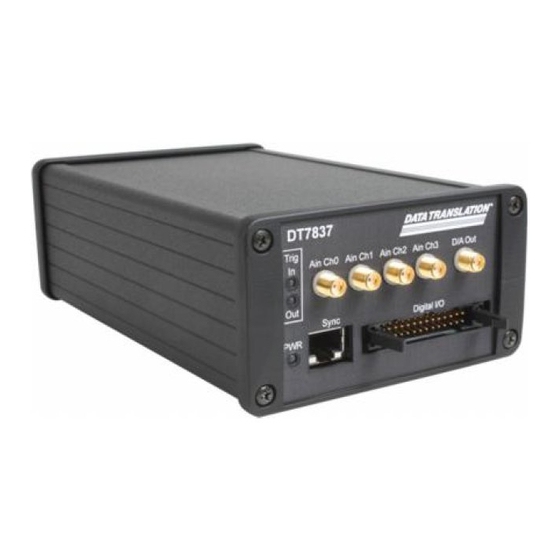
- Page 17 Overview Output Trigger LED (bottom) Input Trigger LED (top) Analog Input Connectors Analog Output Connector (analog output currently not supported in software) Figure 3: Layout of the I/O Block of the DT7837 Module...
-
Page 18: Supported Software
The following software is available for use with the DT7837 module: • DT7837 File I/O Commands – A set of commands in Linux user space for opening a subsystem or stream, configuring a subsystem or stream, acquiring data in the input stream, reading or updating the digital I/O port, and/or writing values to the calibration potentiometers. -
Page 19: Supported Accessories
• EP405 USB to Serial TTL Debug Cable – This 3Mbaud, 1.8 m cable, shown in Figure connects the USB port of the host computer to serial UART connector J13 on the DT7837, allowing you to debug the DT7837 using a terminal interface. - Page 20 • EP361 External Power Supply – This +5 VDC optional power supply and cable, shown in Figure 6, connects to the DIN power connector on the DT7837 module and to the wall power outlet. Figure 6: EP361 +5 VDC External Power Supply...
-
Page 21: Getting Started Procedure
Overview Getting Started Procedure Refer to the DT7837 Getting Started help file on our web site (http://www.datatranslation.com/products/dataacquisition/embedded/DT7837/) for getting started information... - Page 22 Chapter 1...
-
Page 23: Chapter 2: Principles Of Operation
Principles of Operation Block Diagram ............. . . Analog Input Features . -
Page 24: Block Diagram
The DT7837 is an open-source Linux computing platform with a high-accuracy, dynamic signal analyzer front-end. The DT7837 consists of two boards. The bottom board is the ARM block, which includes the ARM processor, PC and embedded connectivity options, and memory, as well as the digital I/O, counter/timer, measure counter, and tachometer circuitry. -
Page 25: Arm Block
Principles of Operation ARM Block The ARM block of the DT7837 module uses the TI Sitara AM3352 processor and its associated peripherals to provide an open-source, single-board computer. The AM3352 supports many different interfaces, many of which are shared on the configurable I/O pins. In addition to the AM3352, the DT7837 module uses an embedded NAND flash and an FPGA. -
Page 26: Micro Sd Card
You can use a micro SD card as a boot source or for general-purpose file and data storage. USB Device (Client) Port The DT7837 module provides a USB 2.0 device (client) port on a type B receptacle. The device port connects to the USB port 0 controller of the AM3352 processor. -
Page 27: Spi Port
A 16-bit address/data multiplexed bus interface is supplied by the processor. In addition to the NAND flash, this bus also supports the FPGA. All control registers for the DT7837 are accessible in the CS1 address space. The CS3 address space provides access to the input FIFO. - Page 28 Chapter 2 Using software, you can specify a general-purpose (general-purpose) output signal as the signal source for one of these destinations: • Digital output (the default signal for each general-purpose output pin) • Clock output for the general-purpose counter/timer (C/T 0) Note that a single general-purpose input may drive several destinations at the same time.
-
Page 29: Analog Input Features
Input Ranges and Gains The DT7837 module provides an input range of ±10 V and software-selectable gains of 1 and 10. This provides effective input ranges of ±10 V (when the gain is 1) and ±1 V (when the gain... -
Page 30: Iepe Functions
IEPE Functions Applications that require accelerometer, vibration, noise, or sonar measurements often use IEPE sensors. IEPE conditioning is built-in to the analog input circuitry of the DT7837 module. The modules support the following software-programmable IEPE functions for each analog input channel: •... -
Page 31: Input Triggers
30, you must specify a start trigger to start acquisition. The DT7837 module supports the following sources for the start trigger; you configure the trigger source and its parameters using software: • Software trigger – A software trigger event occurs when you start the analog input operation (the computer issues a write to the module to begin conversions). -
Page 32: Input Clock Source And Sampling Frequency
= ((2.0f * counts)/(1<<24) – 1.0f) Note: The DT7837 driver sets the threshold level as close as possible to the value that you specify. However, the value that you specify may not be the actual value that is set. You can return the actual threshold level that was set using software. -
Page 33: Data Format And Transfer
Data Format and Transfer The DT7837 has an input FIFO of 2 kSamples (8 kBytes). Each sample of the DT7837 is a 32-bit value. The DT7837 module uses offset binary data encoding, where 000000 represents negative full-scale, and FFFFFFh represents positive full-scale. -
Page 34: Tachometer Input Features
83 ns (1/12 MHz). You can read the number of counts between two consecutive starting edges of the tachometer input signal by including channel 4 for the DT7837 in the analog input channel list. The starting edge is programmable (either rising or falling). - Page 35 Principles of Operation When you read the value of the tachometer input as part of the analog input data stream, you might see results similar to the following: Table 1: An Example of Reading the Tachometer Input as Part of the Analog Input Data Stream Tachometer Time A/D Value...
-
Page 36: General-Purpose Counter/Timer Features
• C/T operation modes, described on page 39 C/T Channels DT7837 modules provide one 32-bit, general-purpose counter/timer (C/T 0). As shown in Figure 9, the counter/timer accepts a clock input and gate input signal and outputs a pulse (clock output signal). -
Page 37: C/T Clock Input Sources
Unless you are using a software gate (no gate), define one of the general-purpose input pins of the Digital connector on the DT7837 module as the external C/T gate input using software. Then, physically connect the external gate signal to the selected pin. (Refer to... -
Page 38: Pulse Output Period, Pulse Width, And Polarity
If you want to perform a C/T output operation, define one of the general-purpose output pins (11 to 18) of the Digital connector on the DT7837 module as the external C/T output signal using software. Then, connect the external C/T output signal to the selected pin. (Refer to page 27 for the pin descriptions of the Digital connector.) -
Page 39: Counter/Timer Operation Modes
If you are using an external C/T clock input source, you can output pulses using a maximum frequency of 5 MHz. Counter/Timer Operation Modes The general-purpose counter/timer on the DT7837 module supports the following counter/timer operation modes: • Event counting •... -
Page 40: Rate Generation
Chapter 2 Rate Generation Use rate generation mode to generate a continuous pulse output signal from the counter’s output signal. You can use this pulse output signal as an external clock to pace other operations, such as an analog input or other counter/timer operations. The pulse output operation is enabled whenever the counter’s gate signal is at the specified level. -
Page 41: Non-Repeatable One-Shot
Principles of Operation Non-Repeatable One-Shot Use non-repeatable one-shot mode to generate a single output pulse from the counter whenever the specified edge is detected on the counter’s gate signal (after the pulse period from the previous output pulse expires). Any gate signals that occur while the pulse is being output are not detected by the module, as shown in Figure 11. -
Page 42: Idle Mode
Chapter 2 • The general-purpose output signal to use for the C/T clock output signal. Ensure that you physically connect the C/T output signal to this output pin. Refer to page 27 for the pin descriptions of the Digital connector. •... -
Page 43: Measure Counter Features
Principles of Operation Measure Counter Features DT7837 modules provides one measure counter. Using this counter, you can measure the frequency, period, or pulse width of a single signal or the time period between two signals and return the value in the analog input stream. This is useful for correlating the analog input data with digital positional data, measuring the frequency of a signal, or as a tachometer. - Page 44 Chapter 2 • A flag (called Stale) indicating whether or not the data is new. This flag is used only when the start edge and the stop edge is set to use the same pin and edge. If the Stale flag is set as Used (the default value), the most significant bit (MSB) of the value is set to 0 to indicate new data;...
- Page 45 Principles of Operation • If the input subsystem sample rate is slower than the selected measurement period, then a new count value is stored as each period measurement completes. When an input subsystem sample occurs, the most recently stored measure count is written into the input data stream.
- Page 46 Chapter 2 • Pulse width of the start and stop signal/edges (rising to falling edge or falling edge to rising edge). You can calculate the period as follows: − Pulse width = 1/Frequency − Pulse width = (Number of counts – 1)/48 MHz where 48 MHz is the internal measure counter frequency...
-
Page 47: Digital I/O Features
Digital I/O Lines DT7837 modules support one digital input port, consisting of up to 8 digital input lines (lines 0 to 7) and one digital output port, consisting of up to 8 digital output lines (lines 0 to 7). The resolution is fixed at 8 bits. -
Page 48: Triggering Acquisition On Multiple Modules
Chapter 2 Triggering Acquisition on Multiple Modules The internal clock on the DT7837 module is derived from the 48 MHz crystal oscillator and provides the timing for the analog input subsystem on the module. You can start acquisition on multiple modules by connecting all modules to a shared external... -
Page 49: Chapter 3: Troubleshooting
Troubleshooting Technical Support ............. If Your Module Needs Factory Service . -
Page 50: Technical Support
Chapter 3 Technical Support Should you experience problems using the DT7837 module, follow these steps: 1. Read all the appropriate sections of this manual and the DT7837 File I/O Programming Manual. 2. Refer to the supplied example programs for clarification. -
Page 51: If Your Module Needs Factory Service
Troubleshooting If Your Module Needs Factory Service If your module must be returned to Data Translation, do the following: 1. Record the module’s serial number, and then contact the Customer Service Department at (508) 481-3700, ext. 1323 (if you are in the USA) and obtain a Return Material Authorization (RMA). - Page 52 Chapter 3...
-
Page 53: Chapter 4: Calibration
Calibration Overview ..............Using the Calibration Utility . -
Page 54: Overview
Chapter 4 Overview DT7837 modules are calibrated at the factory and should not require calibration for initial use. We recommend that you check and, if necessary, readjust the calibration of the analog circuitry every six months using the DT7837 Calibration Utility. -
Page 55: Using The Calibration Utility
Calibration Using the Calibration Utility To use the command-line DT7837 Calibration Utility, perform the following steps: 1. From the usr/local/dt7837/dt7837-calibration directory on the module, type dt7837cal, and press Enter. The main screen of the DT7837 Calibration Utility appears. 2. Once the calibration utility is running, calibrate the analog input circuitry either... -
Page 56: Calibrating The Analog Input Subsystem
To calibrate the analog input circuitry, you need to connect an external precision voltage source to the DT7837 module that is capable of generating 0.0000 V to +9.3750 V. Connect the precision voltage source to the first analog input channel that you want to calibrate (typically analog input channel 0). -
Page 57: Using The Manual Calibration Procedure
Calibration Using the Manual Calibration Procedure The DT7837 has two gains (1 and 10) and two power modes: low power mode and high power mode. Low power mode is calibrated when you specify a sampling frequency less than 52.734 kHz. High power mode is calibrated when you specify a sampling frequency greater than 52.734 kHz. -
Page 58: Restoring Factory-Calibration Settings
If you wish, you can restore the analog input calibration values for each channel to their original factory settings by selecting 3: Restore all analog input factory calibration settings from the main menu of the DT7837 Calibration Utility. A prompt is displayed to inform that the values were reset. -
Page 59: Appendix A: Specifications
Specifications Analog Input Specifications ........... . Digital Input Specifications. -
Page 60: Analog Input Specifications
Appendix A Analog Input Specifications Table 4 lists the specifications for the analog input subsystem on the DT7837 module. Table 4: Analog Input Subsystem Specifications Feature DT7837 Specifications Number of analog input channels 4, single-ended Resolution 24 bits Ranges and gains Gain of 1: ±10 V... - Page 61 Specifications Table 4: Analog Input Subsystem Specifications (cont.) Feature DT7837 Specifications DC Accuracy Offset error ±1 mV μ μ Offset error temperature coefficient ±(7.2 V/° C )/ Gain) ± 100 V/° C Gain error Gain of 1: ±0.02% Gain of 10: ±0.5%...
- Page 62 Appendix A e. ENOB, SINAD, SNR, THD, and SFDR measurements were made with a 16384 point FFT with a minimum 4-term Blackman Harris window. f. Effective Number of Bits (ENOB) is calculated from the SINAD value with adjustment for level below full-scale of the input signal.
-
Page 63: Digital Input Specifications
Specifications Digital Input Specifications Table 5 lists the specifications for the digital input signals available on the Digital connector of the DT7837 module. Table 5: Digital Input Specifications Feature Specifications Number of general-purpose inputs Input type 3.3 V high-speed CMOS, Schmitt trigger, 5 V tolerant Ω... -
Page 64: Digital Output Specifications
Appendix A Digital Output Specifications Table 5 lists the specifications for the digital output signals available on the Digital connector of the DT7837 module. Table 6: Digital Output Specifications Feature Specifications Number of general-purpose outputs Output type LVTTL Logic high output voltage 2.4 V minimum... -
Page 65: Tachometer Input Specifications
Specifications Tachometer Input Specifications Table 7 lists the specifications for the tachometer input available on the Digital connector of the DT7837 module. Table 7: Tachometer Input Specifications Feature Specifications Number of channels Resolution 31 bits per channel Input voltage range ±30 V... -
Page 66: Measure Counter Specifications
Appendix A Measure Counter Specifications Table 8 lists the specifications for the measure counter on the DT7837 module. Table 8: Measure Counter Specifications Feature Specifications Number of measure counters Resolution 31 bits per channel Clock frequency for measurement counters 48 MHz (20.8 ns resolution) -
Page 67: General-Purpose Counter/Timer Specifications
Specifications General-Purpose Counter/Timer Specifications Table 7 lists the specifications for the general-purpose counter/timer (C/T 0) on the DT7837 module. Table 9: General-Purpose Counter/Timer Specifications Feature Specifications Number of general-purpose counter/timers Clock sources Internal: 48 MHz reference clock External: General-purpose inputs 0 to 7 on the Digital connector... -
Page 68: Trigger Specifications
Appendix A Trigger Specifications Table 10 lists the specifications for the triggers on the DT7837 module. Table 10: Trigger Specifications Feature DT7837 Specifications Trigger sources Internal software trigger: Software-initiated External digital trigger: Software-selectable, general-purpose inputs 0 to 7 on the Digital connector... -
Page 69: Master Oscillator Specifications
Specifications Master Oscillator Specifications Table 11 lists the specifications for the master oscillator on the DT7837 module. Table 11: Master Oscillator Specifications Feature Specifications Frequency 48 MHz Frequency stability ±30 ppm a. Stability budget consists of initial tolerance, operating temperature range, rated power supply voltage change, load change, 10-year aging, shock, and vibration. -
Page 70: Power, Physical, And Environmental Specifications
Appendix A Power, Physical, and Environmental Specifications Table 12 lists the power, physical, and environmental specifications for the DT7837 module. Table 12: Power, Physical, and Environmental Specifications Feature DT7837 Specifications Power +5 VDC @ 2 A maximum Warm-up time 1 hour... -
Page 71: Regulatory Specifications
Specifications Regulatory Specifications The DT7837 module is CE-compliant. Table 13 lists the regulatory specifications for the DT7837 module. Table 13: Regulatory Specifications Feature DT7837 Specifications Emissions (EMI) FCC Part 15, Class A EN55011:2007 (Based on CISPR-11, 2003/A2, 2006) Immunity EN61326-1:2006... -
Page 72: Connector Specifications
Appendix A Connector Specifications Table 14 lists the connector specifications for the DT7837 module. Table 14: Connector Specifications Board Reference Part Number of Connector Part Number of Connector Designator on Module Mating Connector Analog input SMA connectors J1-J5 on I/O block Amphenol Connex 132203 –... -
Page 73: External Power Supply Specifications
Table 15 lists the specifications for the option EP361 +5 V external power supply that is used with the DIN power connector on the DT7837 module. Table 15: Specifications for the Optional EP361 External Power Supply Used with the DIN Connector on the DT7837 Module... - Page 74 3-position header on the DT7837 module. Table 16: Specifications for the External Power Supply Used with the 3-Position Header on the DT7837 Module Feature Specifications Output voltage...
-
Page 75: Appendix B: Connector Pin Assignments And Led Status Indicators
Connector Pin Assignments and LED Status Indicators Analog Input Connectors ............Digital Connector . -
Page 76: Analog Input Connectors
Analog Input Connectors Figure 13 shows the layout of the analog input SMA connectors (connectors J1-J5) on the I/O block (top board) of the DT7837 module. Channel n Analog In Channel n Analog In Return Figure 13: Analog Input Connectors... -
Page 77: Digital Connector
Figure 14 shows the layout of the 26-pin Digital connector (J8) on the ARM block (bottom board) of the DT7837 module. This connector brings out the tachometer, GPIO, and event output signals for the module. Figure 14: Layout of the Digital Connector Table 17 lists the pin assignments for the Digital connector on the DT7837 module. - Page 78 Appendix B Using software, you can specify a general-purpose input signal as the signal source for the following destinations: • Digital input (the default signal for each general-purpose input pin) • External A/D trigger input • Gate input for the general-purpose counter/timer (C/T 0) •...
-
Page 79: Usb Device (Client) Connector
Figure 15: Layout of the USB Type B Connector for the USB Device (Client) Port Table 18 lists the pin assignments for the USB type B connector on the DT7837 module for the USB device (client) port. Table 18: Pin Assignments for the USB Type B Connector for the USB Device (Client) Port... -
Page 80: Usb Host Connector
Figure 16: Layout of the USB Type A Connector for the USB Host Port Table 19 lists the pin assignments for the USB type A connector on the DT7837 module for the USB host port. Table 19: Pin Assignments for the USB Type B Connector for the USB Device (Client) Port... -
Page 81: Ethernet Connector
1 2 3 4 5 6 7 8 LED1 LED2 Figure 17: Layout of the Ethernet Connector Table 20 lists the pin assignments for the Ethernet connector on the DT7837 module. Table 20: Pin Assignments for the Ethernet Connector Connector Connector Pin Number... -
Page 82: Micro Sd Card Connector
Card Detect Switch Bottom View Figure 18: Micro SD Card Connector Table 21 lists the pin assignments for the Micro SD card connector on the DT7837 module. Table 21: Pin Assignments for the Micro SD Card Connector Connector Connector Pin Number... -
Page 83: External +5 V Power Connector
Connector Pin Assignments and LED Status Indicators External +5 V Power Connector The DT7837 module provides two connectors for attaching a +5 VDC external power supply: a DIN connector and a 3-position Phoenix header. Figure 19 shows the layout of the DIN power connector (J6) on the ARM block (bottom board) of the DT7837. - Page 84 Figure 20: Layout of the 3-Position Phoenix Header Table 23 lists the terminal assignments for the 3-position header on the DT7837 module. Table 23: Terminal Assignments for the 3-Position Header (TB1) on the DT7837 Module Terminal Number Signal Description +5 VDC...
-
Page 85: Serial Connectors
Connector Pin Assignments and LED Status Indicators Serial Connectors Figure 15 shows the layout of the 6-pin serial connectors (J12, J13, and J14) on the ARM block (bottom board) of the DT7837 module. Serial Port 0 Serial Port 1/ Port... -
Page 86: Spi Connector
Appendix B Table 24 lists the pin assignments for serial port 0 on the DT7837 module. Table 24: Pin Assignments for Serial Port 0 (J13) on the DT7837 Module Connector Pin Number Signal Description DGND Not Connected Not Connected UART0_RX... -
Page 87: Serial Port 1 / I 2 C2 Connector
Table 26 lists the pin assignments for the Serial port 1/ I C connector on the DT7837 module. Table 26: Pin Assignments for Serial Port 1 / I C Connector (J14) on the DT7837 Module Pin Number Signal Description UART1_RX... -
Page 88: I/O Block Connector
Appendix B I/O Block Connector Figure 15 shows the layout of the I/O block connector (J9) on the DT7837 module. Figure 25: I/O Block Connector (J9) - Page 89 Connector Pin Assignments and LED Status Indicators Table 27 lists the pin assignments of the I/O block connector on the DT7837 module (on both the ARM block and the I/O block). Table 27: Pin Assignments for the I/O Block Connector (J9)
- Page 90 Appendix B Table 27: Pin Assignments for the I/O Block Connector (J9) Connector Connector Pin Number Signal Description Pin Number Signal Description In Serial Data 4 In Serial Data 5 In Serial Data 6 In Serial Data 7 Ground Ground In Parallel Data 0 In Parallel Data 1 In Parallel Data 2...
-
Page 91: Stp26 Screw Terminal Panel
STP26 Screw Terminal Panel The STP26 contains one 26-pin connector and a screw terminal block (TB1). The 26-pin connector provides access to the signals from the Digital connector on the DT7837 module. Figure 26 shows the layout of the STP26 screw terminal panel. - Page 92 Appendix B Table 28: Screw Terminal Assignments for the STP26 Screw Terminal Panel Screw Terminal Signal Description Shield Digital Ground +5 V Digital Ground Tachometer Input Digital Ground Reserved for future use Digital Ground Digital Ground General-Purpose Output 7 General-Purpose Output 6 General-Purpose Output 5 General-Purpose Output 4 General-Purpose Output 3...
-
Page 93: Led Status Indicators
Connector Pin Assignments and LED Status Indicators LED Status Indicators The DT7837 module has a Power LED indicator on the ARM block (bottom board) and trigger LEDs on the I/O block (top board), as shown in Figure Input Trigger LED... - Page 94 Appendix B...
-
Page 95: Index
I/O operations analog input subsystem continuous digital input running the calibration utility lines channels synchronous read analog input synchronous write counter/timer digital trigger digital I/O DIN power connector digital input DT7837 Calibration Utility measure counter duty cycle tachometer client port, USB... - Page 96 Index EEPROM kernel device driver embedded NAND flash encoding data environmental specifications LED status indicators EP405 USB to serial TTL debug cable Input Trigger EP406 cable Output Trigger errors, analog input Power Ethernet connector lines, digital I/O event counting excitation current source external clock external digital trigger master oscillator...
- Page 97 Index technical support threshold trigger ranges, analog input transferring input data rate generation triggers regulatory specifications external resolution software analog input specifications digital I/O threshold returning boards to the factory troubleshooting TTL trigger type A connector type B USB connector sample clock SD card SDRAM...
- Page 98 Index...
Need help?
Do you have a question about the DT7837 and is the answer not in the manual?
Questions and answers