Table of Contents
Advertisement
Quick Links
Please read these instructions completely before proceeding with installation
F
Outboard
Item
Description
A
Air Sleeve
B
Upper Bracket
C
Lower Bracket
D
U-Bolt
E
Lower Clamp Bar
3
F
/
" Self-Tapping Screw
8
3
G
/
" Flat Washer
8
1
3
H
/
" x
/
" Flat Head Screw
2
4
I
3
/
" Hex Jam Nut
4
J
1
/
" Straight Fitting
8
K
¾" Star Washer
Kit No. 59554
AA
G
M
C
H
Ride Control Kit Parts List
Quantity
2
2
2
2
2
6
6
2
2
2
2
Technical Support
1-800-248-0892
J
I
K
B
A
D
E
G
L
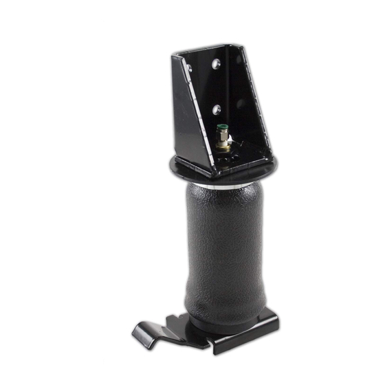
Figure 1
Item
L
M
N
AA
BB
CC
DD
EE
FF
GG
Ext. 2
by
www.airliftcompany.com
FRAME
L
N
Forward
Driver Side
Description
3
/
"-16 Nyloc Nut
8
3
/
"-16 Bolt
8
3
/
" Large Flat Washer
8
Air Line Assembly
Tie Strap
Valve Caps
5
/
" Flat Washer
16
Rubber Washer
5
/
" Star Washer
16
5
/
" Hex Nut
16
MN-604
(01412)
NPR 4732
Quantity
6
2
2
1
6
2
2
2
2
4
1
Advertisement
Table of Contents

Subscribe to Our Youtube Channel
Related Manuals for Air Lift Ride Control 59554


Summary of Contents for Air Lift Ride Control 59554
- Page 1 MN-604 (01412) NPR 4732 Kit No. 59554 www.airliftcompany.com Please read these instructions completely before proceeding with installation FRAME Forward Outboard Driver Side Figure 1 Ride Control Kit Parts List Item Description Quantity Item Description Quantity Air Sleeve "-16 Nyloc Nut Upper Bracket "-16 Bolt Lower Bracket...
-
Page 2: Tools Needed
Tools Needed Hose Cutter, Razor Blade, or Sharp Knife ", ", and " open-end or box wrenches Hoist or Floor Jacks Crescent Wrench Safety Stands Ratchet with " " and " deep well sockets Safety Glasses " and " drill bits (very sharp) Air Compressor, or Compressed Air Source Heavy Duty Drill Torque Wrench... -
Page 3: Assembling The Air Spring Unit
II. Assembling the Air Spring Unit 1. Install the air fitting (J) to the top of the air sleeve (A). Tighten 1 and turns (Figure 1). 2. Attach the lower bracket (C) to the bottom of the air sleeve (A) using the small flat head screw (H). Tighten securely (Figure 1). - Page 4 10. IMPORTANT: Be sure to cover the air fitting with piece of tape to prevent metal shavings from getting into the fitting or sleeve. 11. Check alignment, adjust if needed, then center punch and drill two more holes in the upper bracket. 12.
-
Page 5: Installing The Air Lines
3. Cut the air line assembly (AA) in two equal lengths (Figure CAUTION: When cutting or trimming the air line, use a hose cutter (Air Lift P/N 10530), a razor blade or a sharp knife. A clean, square cut will ensure against leaks. -
Page 6: Finishing The Installation
V. Finishing the Installation 1. With the air line in the fitting, inflate to 10 p.s.i., adjust the sleeve in or out for alignment, and secure air sleeve to upper bracket by tightening the nylon nut to 4 ft-lbs (Figure 1). - Page 7 7. Should it become necessary to raise the vehicle by the frame, make sure the system is at minimum pressure (10 p.s.i.) to reduce the tension on the suspension/brake components. Use of on–board leveling systems do not require deflation or disconnection. Thank you for purchasing Air Lift Products Mailing Address: Street Address:...
-
Page 8: Product Use Information
No. Adding air springs will not change the weight ratings (GAWR, GCWR and/or GVWR) of a vehicle. Exceeding the GVWR is dangerous and voids the Air Lift warranty. Q. Is it necessary to keep air in the air springs at all time and how much pressure will they need? The minimum air pressure should be maintained at all times. -
Page 9: Guidelines For Adding Air
The consumer is responsible for installation/reinstallation (labor charges) of the product. Air Lift Company reserves the right to change the design of any product without assuming any obligation to modify any product previously manufactured.
Need help?
Do you have a question about the Ride Control 59554 and is the answer not in the manual?
Questions and answers